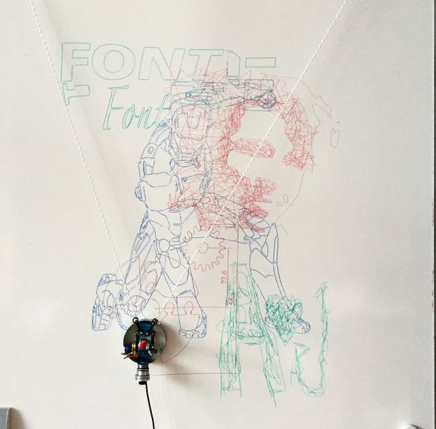
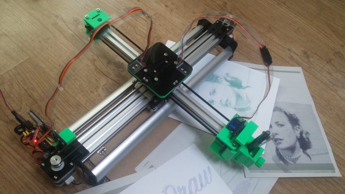
The 4xiDraw is a simple, modern, precise, and versatile pen plotter, capable of writing or drawing on almost any flat surface. It can write with your favorite fountain pens, permanent markers, and other writing implements to handle an endless variety of applications. Its unique design features a writing head that extends beyond the machine, making it possible to draw on objects bigger than the machine itself.
Applications:
The 4xiDraw is an extremely versatile machine, designed to serve a wide variety of everyday and specialized drawing and writing needs. You can use it for almost any task that might normally be carried out with a handheld pen. It allows you to use your computer to produce writing that appears to be handmade, complete with the unmistakable appearance of using a real pen (as opposed to an inkjet or laser printer) to address an envelope or sign one’s name. And it does so with precision approaching that of a skilled artist, and — just as importantly — using an arm that never gets tired.
Personalize and sign certificates
Formal invitations
Work with small and irregularly shaped paper
Party invitation with fine-point markers
Printing text with a fountain pen
Stipple drawing with pen
Precision drawing with rollerball pens
Large writing with permanent marker
4xiDraw is used by a genuinely diverse range of people, including (to name a few):
Digital artists, using 4xiDraw to plot their artwork
Celebrities, politicians, and elected officials, using 4xiDraw as a signature machine
University officials and other educators, to sign diplomas and certificates
Educators, introducing students to digital design and fabrication
Real estate and insurance agents, who would very much like you to open their “handwritten” envelopes
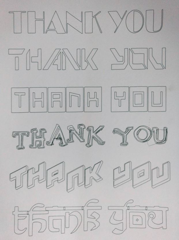
Online retailers, including a personalized thank you note with your order
Hotels that would like to leave a personalized welcome note for guests
Makerspaces and hackerspaces, providing a versatile low-cost fabrication tool
Pen and ink manufacturers, using 4xiDraw to test their pens and inks
Smartphone and tablet hardware makers, using a stylus to test their hardware
Mobile device software authors, using a stylus to test their software
People without use of their hands, who would like to send “handwritten” letters
Woodworkers, laying out joinery markings directly onto wood
Research scientists, as a low-cost XY motion platform
Galleries, for numbering of limited-edition artwork
Calligraphers, who could use a little wrist relief for certain types of busywork
Handling pens and paper:
Printable area: US Letter + A4
Pen holder: Vertical configuration
Pen holder: 45-degree configuration
Pick the right angle for each writing implement
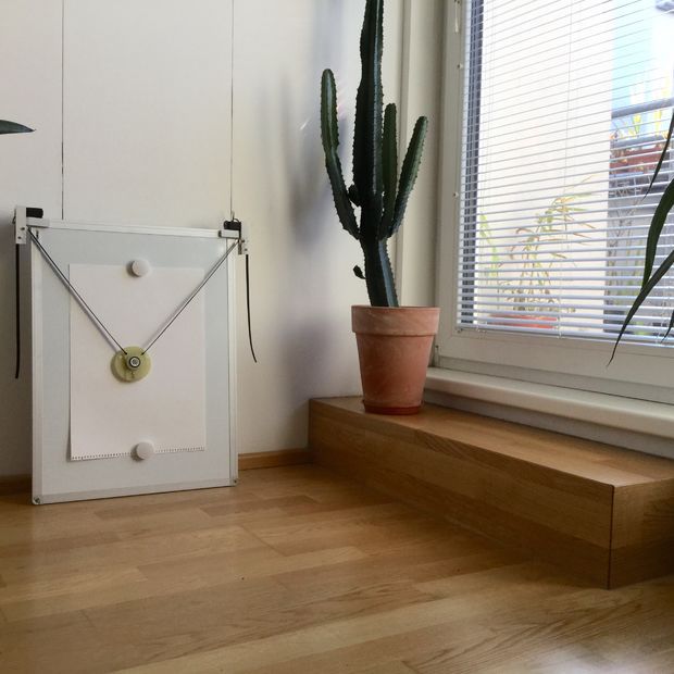
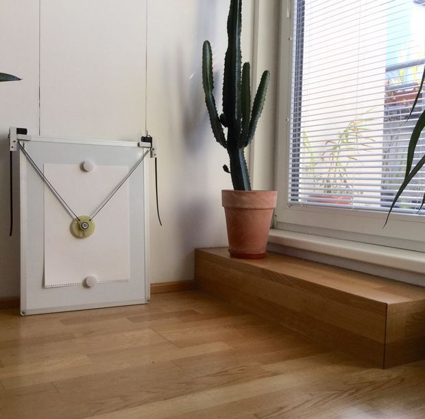
The XY travel (printable area) of the 4xiDraw is just over US letter (8 1/2 × 11″) and A4 (297 × 210 mm) paper sizes. It can work with any paper up to and including that size, including envelopes and note cards. The 4xiDraw comes with a mounting easel (board with clips) that can be used for holding paper, cards, and envelopes of various sizes. However, its unique design features a drawing head that extends beyond the body of the machine, making it possible to also draw on flat objects bigger than the machine itself. For example, you can set it right on top of a box to write an address or add decorations. You can even set it on top of a poster board, chalkboard, or whiteboard to draw graphics in place. The pen holder fits a wide variety of pens, including Sharpie fine and ultra-fine point markers, most rollerball and fountain pens, small-bodied whiteboard markers, and so forth. It can even hold a fountain pen at a proper angle of 45° to the paper. You can also use implements that aren’t pens, such as pencils, chalk, charcoal, brushes, and many others. However, you’ll get the best results with instruments such as fountain pens and rollerball pens, which do not require the user to apply pressure.
Getting Started
The 4xiDraw comes fully assembled, tested, and ready to use, right out of the box. A universal-input plug-in power supply is included with the 4xiDraw, as is a USB cable, and an optional paper-holding easel. Assuming that you’ve installed the software first, you can be up and plotting within minutes of opening the box. To operate 4xiDraw, you will need a reasonably modern computer with an available USB port (Mac, Windows or Linux), plus internet access to download necessary software. Pens and paper are not included. (You can use your own! 4xiDraw does not require proprietary pens or paper.) 4xiDraw is normally controlled through a set of extensions to Inkscape, the excellent, popular and free vector graphics program. Basic operation is much like that of a printer driver: you import or make a drawing in Inkscape, and use the extensions to plot your text or artwork. It’s all handled through a straightforward graphical user interface, and works cleanly on Mac, Windows and Linux. Additional software interfaces available to 4xiDraw owners include 4xiDraw Merge (beta), for auto-populating documents with data sourced from a CSV spreadsheet file.
More about 4xiDraw
4xiDraw V1 is the first-generation version of the 4xiDraw, redesigned from the ground up for high performance. It features smooth rolling wheels on custom aluminum extrusions, specially designed for high stiffness and light weight. Its sturdy, rigid construction gives it finer quality output and in most applications allows it to operate with significantly higher precision and speed than competing and previous generation machines. Inspired by and source code from AxiDraw AxiDraw is a project by Evil Mad Scientist Laboratories.
4xiDraw V1 is a clone of the famous Axidraw. It’s a plotter to draw. Used an “Arduino Nano” control card and a “CNC Shield” card. Using the “Inkscape” vector graphics program along with a special “plug in”, you can create several G-Code files, starting with a drawing. Universal G-code Sender (Java) will do the rest. __________________________________________________________
For more details, you can find all the information on Misan’s Instructables page: http://www.instructables.com/id/4xiDraw/__________________________________________________________
4xiDraw machines are designed and manufactured by Zalophus’s DesignHouse, with both foreign and domestic components. 4xiDraw comes with lifetime technical support. We stand by our machines, and we’re here to help whenever you need it.
What comes with the machine:
The 4xiDraw V1 drawing machine, fully assembled, tested, and ready to use.
Universal-input plug-in power supply with US-style plug. For other regions, an inexpensive plug shape (but not voltage) adapter will be needed.
Additional specifications:
Performance:
Usable pen travel (inches): 11.81 × 8.58 inches (Just over US letter size)
Usable pen travel (millimeters): 300 × 218 mm (Just over A4 size)
Vertical pen travel: 0.7 inch (17 mm)
Maximum XY travel speed, rapid: 11 inches (28 cm) per second.
Native XY resolution: 2032 steps per inch (80 steps per mm)
Reproducibility (XY): Typically better than 0.005 inches (0.1 mm) at low speeds.
Physical:
Major structural components are machined and/or folded aluminum.
Holds pens and other drawing instruments up to 5/8″ (16 mm) diameter.
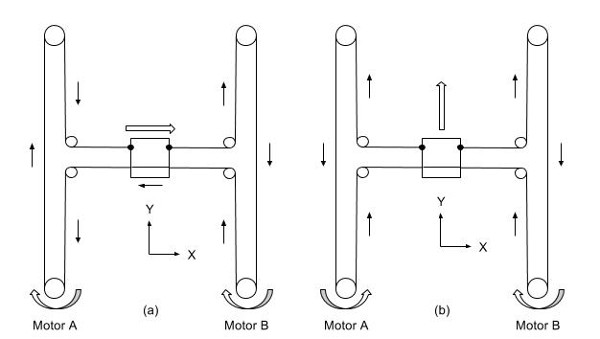
There is a family of 2 axis mechanisms called H-Bots. They use 2 motors on a single belt to generate motion in 2 axes. The most basic type is the classic H-Bot. ‘H’ comes from the outline of the belts.
Image from Galil Motion Control
The motors turn the same direction for motion in one axis. They turn opposite directions for motion on the other axis. If only one motor turns both axis will move evenly (like 45°, etc). All other angles are possible with the right drive ratios.
CoreXY
The H-Bot is simple, but imparts some twisting forces on the mechanism under some loads that work against accuracy. For example, look at left diagram in the image above. The belt is pulling down on the left side of the ‘H’ and up on the right side. This tries to twist the gantry if there is a resistance to the carriage movement in X. CoreXY addresses this by crossing the belts at one end. A longer belt does increase belt stretch issues though.
Image from CoreXY.com
T-Bots
T Bots are the simplest variety and work well with light loads.
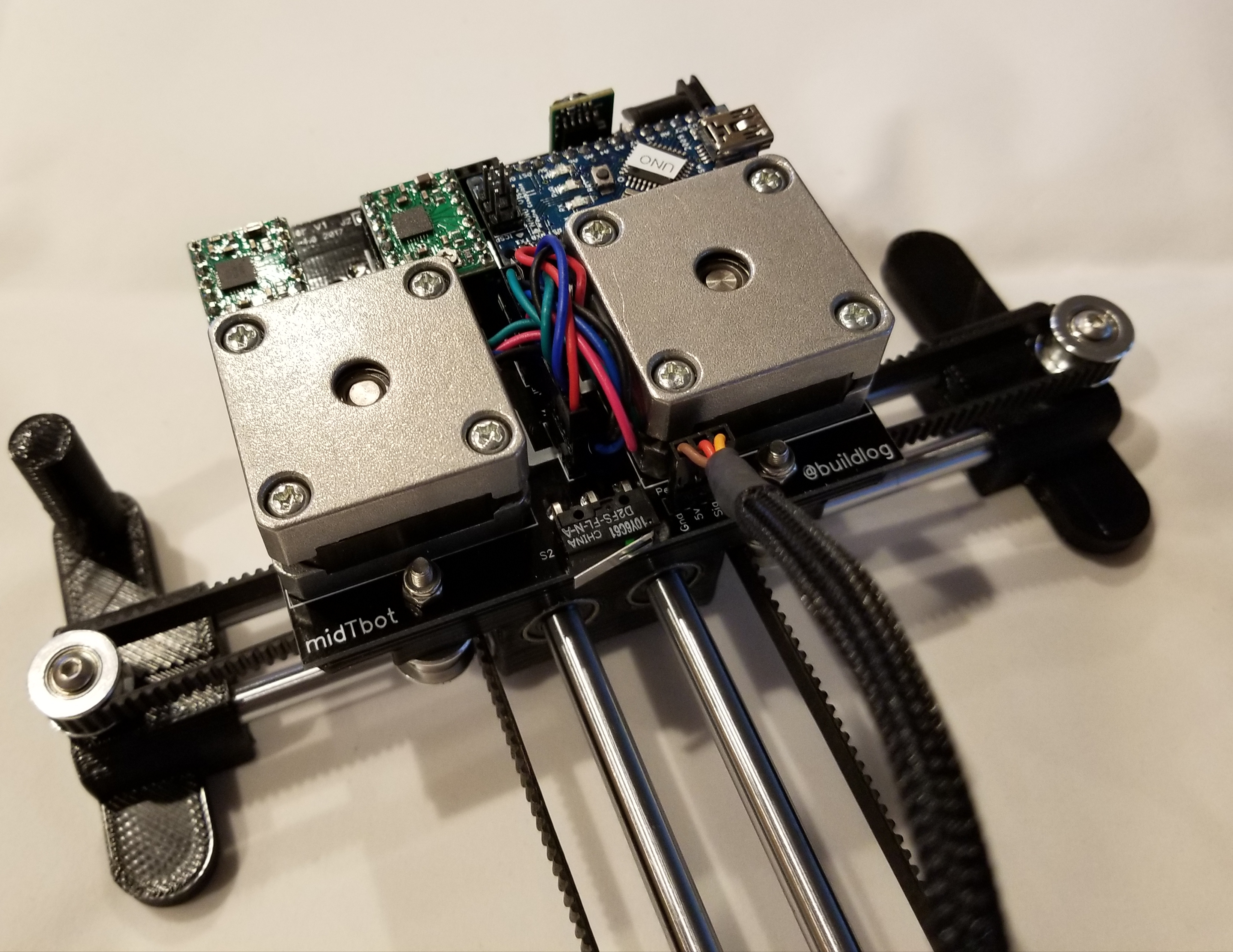
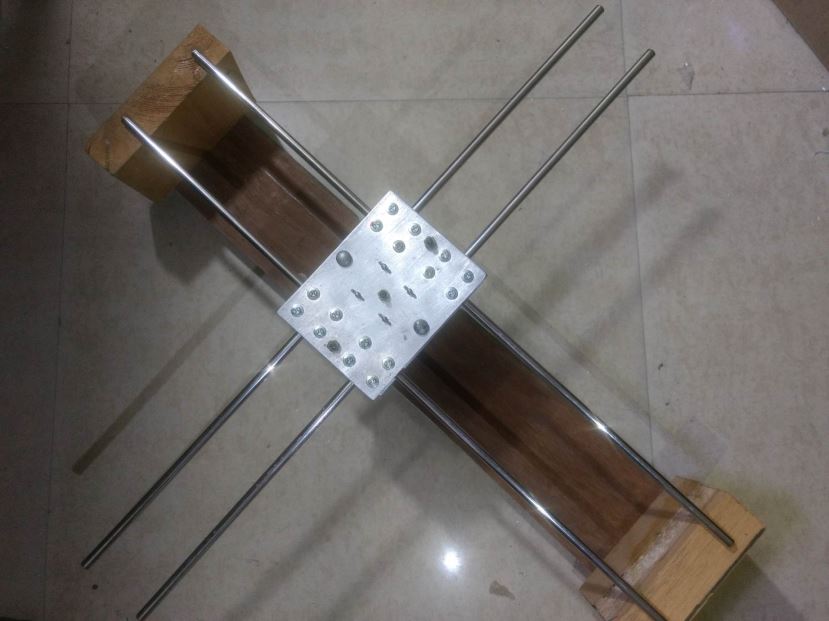
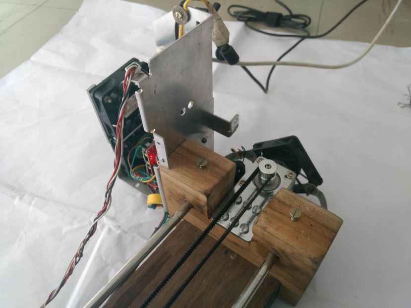
I was trying to make the smallest and simplest drawing machine with a reasonable work area. T-Bots are pretty simple, but the motors on the ends seemed to waste space. I also wanted integrated electronics. Moving the motors to the middle carriage seemed to solve a lot of these problems. It does add the motors to the mass of the moving parts, but only on one axis and they are directly over the linear bearings. It really has an elegant and smooth look to it. The midTbot name comes from middle mounted motors on a T bot. Here is an image of just the XY mechanism running.
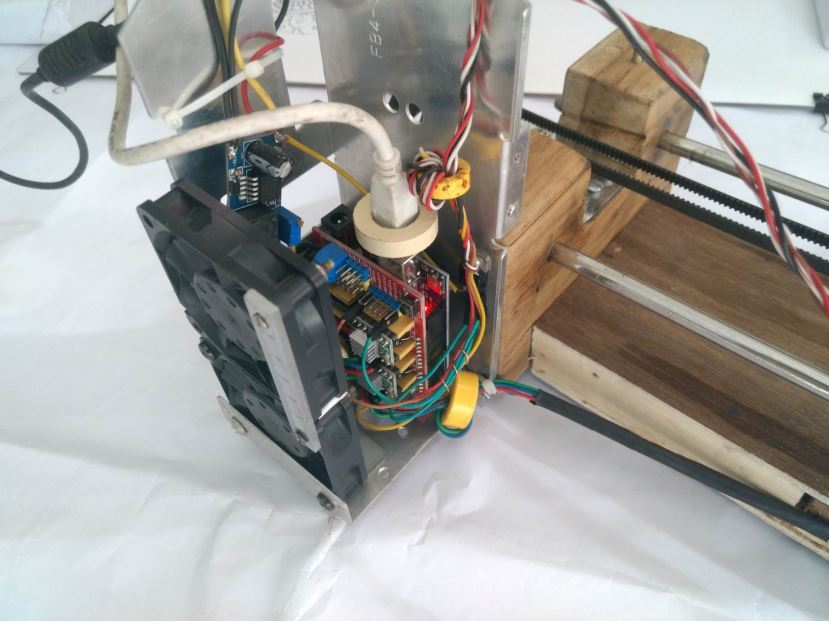
Electronics
The ideal place for the electronics is right by the motors. This will reduce the wiring as much as possible. Putting the homing switches on the middle carriage would further clean up the wiring.
I designed a modular controller that mounts to the top of the middle carriage and under the motors.
The controller will soon be available on Tindie.
Scalability
It is very scalable because you only need to change the rod and belt lengths. No wiring needs to change. The middle mounted motors makes the platform very stable, but if allow the pen carriage to go too far forward, it could tip forward. I think you would need to extend the feet a little forward to counteract that.
A cheap and easy to make CNC based DIY drawing robot
Introduction
Hi. Thank you for showing Interest in this project. This Project was my engineering’s final year capstone project. It took me a month to make this Project and I had fun building it. Below I am writing a step by step DIY guide to help you build your own CNC Drawing Robot. The guide is quite long with both text and video. I have given most details so that you will not feel any problem if you are new to making projects of this kind.
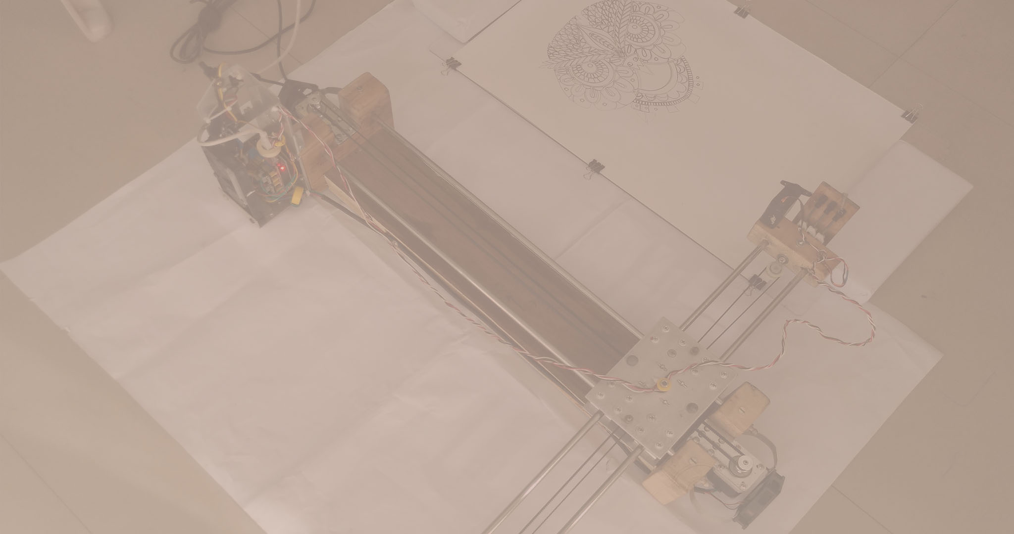
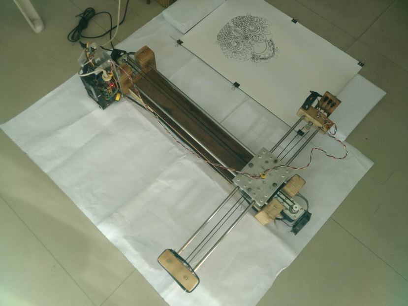
The Crazy Engineer’s Drawing Robot or Arduino GRBL CoreXY Servo Drawbot is a CNC based drawing robot. It is open source and open hardware based project. It uses Arduino UNO (Atmega328p) as the brain of the robot and a special GRBL firmware for G-Code Interpretation and motion control. It also uses a core [X, Y] Cartesian movement to control both X and Y axis. The Z axis is controlled by a servo motor to lift pen up and down.
Crazy Engineer’s Drawing Robot is a simple CNC Drawing Robot, capable of writing or drawing on almost any flat surface. It can write with gel pens, permanent markers, and a variety of other writing implements to handle an endless number of applications. Its writing head extends beyond the machine, making it possible to draw on objects bigger than the machine itself.
Suggested applications include:
• Decoration Drawing
• Computer artwork
• Technical drawing
• Notes and cards
• Writing signatures
• Signing diplomas and other certificates
• “Hand-written” lists
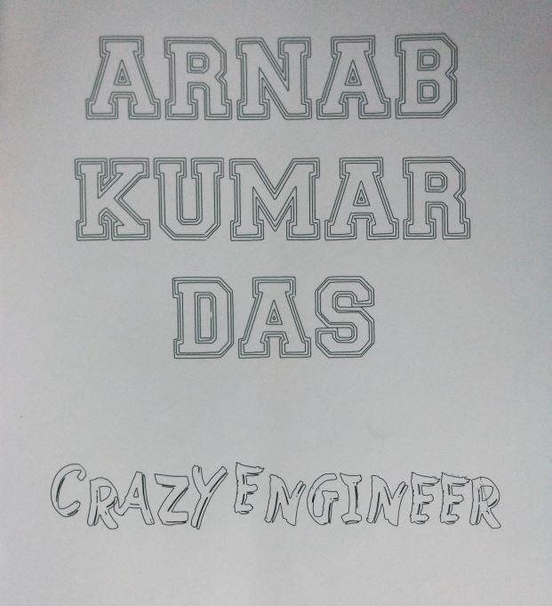
Vector Text
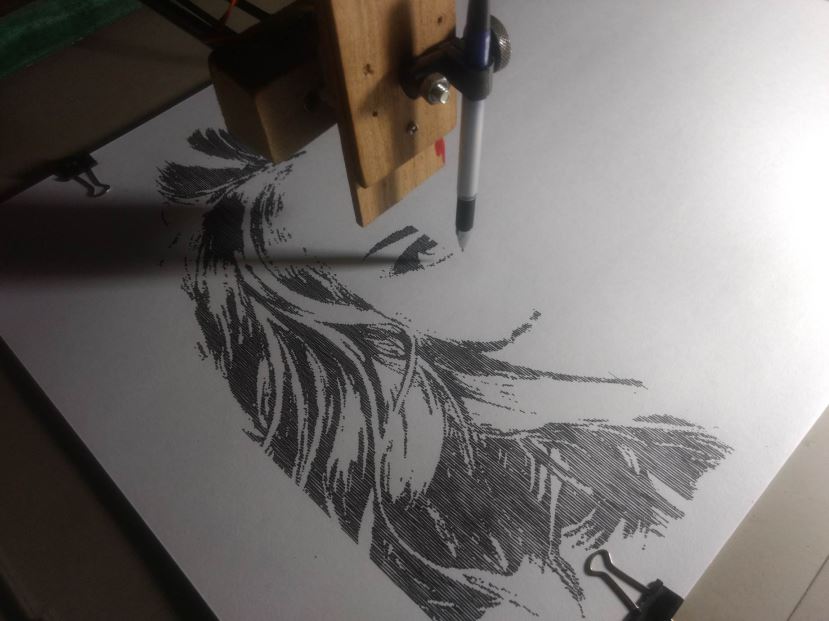
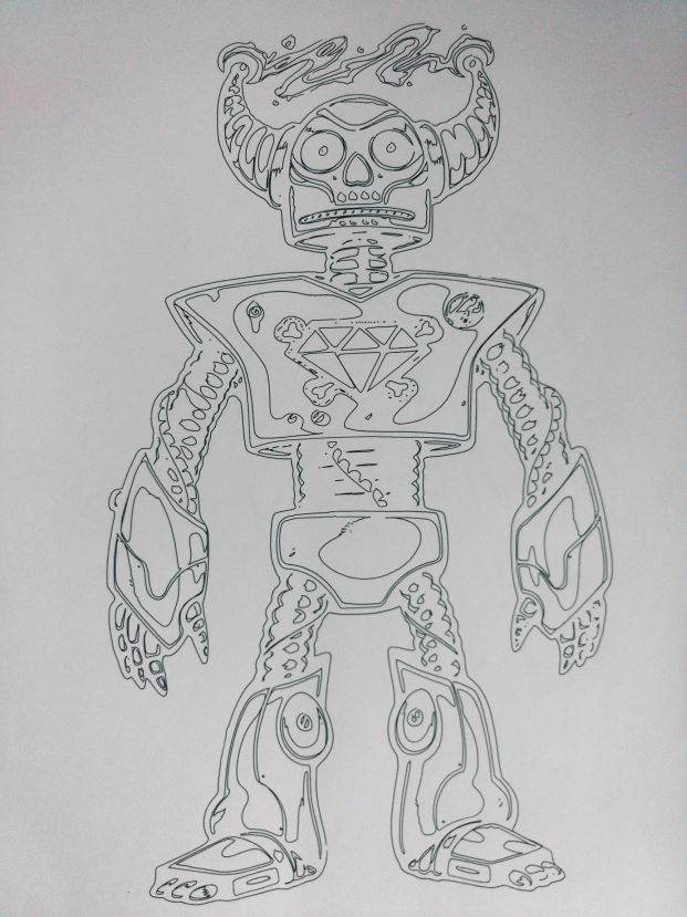
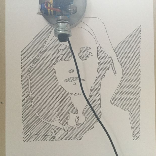
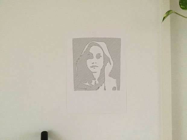
Raster Drawing
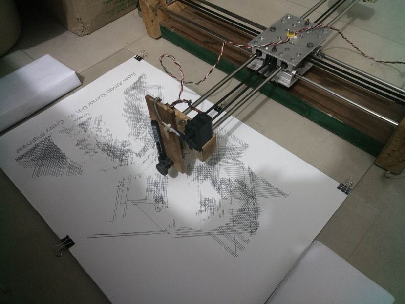
Vector Drawing
Vector Drawing
Project Motivation
When I was in my 2nd year of my engineering I did some research and came across the term CNC and I got fascinated by that. That time I came across a brand called Inventables that manufactures Desktop CNCs for Makers and low volume manufacturing. My early research was on CNC milling and drilling but making a CNC milling or drilling machine requires good investment and that is what I was lacking. Finally, I thought to make a CNC Drawing Robot that required relatively only a fraction of the cost of the CNC Milling machine.
If you Google DRAWBOT you will come across few interesting projects and product out of which :
Collectively I studied all of these and found it cool. But they were mostly using A4 paper so I made one for myself with the largest work area of all above. My Crazy Drawing Robot can handle paper as big as ARCH B.
The dreams of yesterday are the hopes of today and the reality of tomorrow. Science has not yet mastered prophecy. We predict too much for the next year and yet far too little for the next ten.
Project Comparison with AxiDraw
Crazy Engineer’s Drawbot is similar as well as different from AxiDraw:
• Crazy Engineer’s Drawbot is a Cartesian CoreXY movement (H-bot I think) similar to AxiDraw.
• Crazy Engineer’s Drawbot is based on Arduino, while AxiDraw is based on the EBB Driver board
• Crazy Engineer’s Drawbot has a large working area (45×38), like an ARCH B paper bigger than A3, while AxiDraw has a normal working area (30×20), like an A4 paper.
• Crazy Engineer’s Drawbot is Made of Wood to reduce cost, while AxiDraw is in metal (? this is not very clear watching the pictures)
• AxiDraw can write with a fountain pen, Crazy Engineer’s Drawbot not (yet)
• 2 x NEMA 17 Steppers 1.8 Degree Step 12v Torque more than 5kg/cm
• 4 x 8mm smooth rods (I used 8mm, will Suggest you to use 10mm/12mm) 600mm Long
• 8 x SC8UU (Will suggest u to use SC10UU/SC12UU)
• 2 x 20-Tooth GT2 pulleys
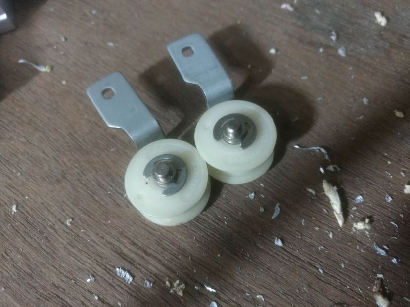
• 10 x F623ZZ Bearings (I used Plastic Pulleys to reduce cost)
• 1 x Micro Servo SG90 (Later I Used a Bigger Servo for Quality)
• 1 x Arduino UNO
• 1 x CNC Shield V3
• 2 x Pololu Step Sticks A4988 Stepper Driver
• 1 x GT2 Belt (3 meters long)
• 1 x Hard Wood 1mx20cmx4cm
• 8 x 30mm M3 screws with nuts
• 3 x BLDC Fan (Not Necessary if you are not in tropical climate)
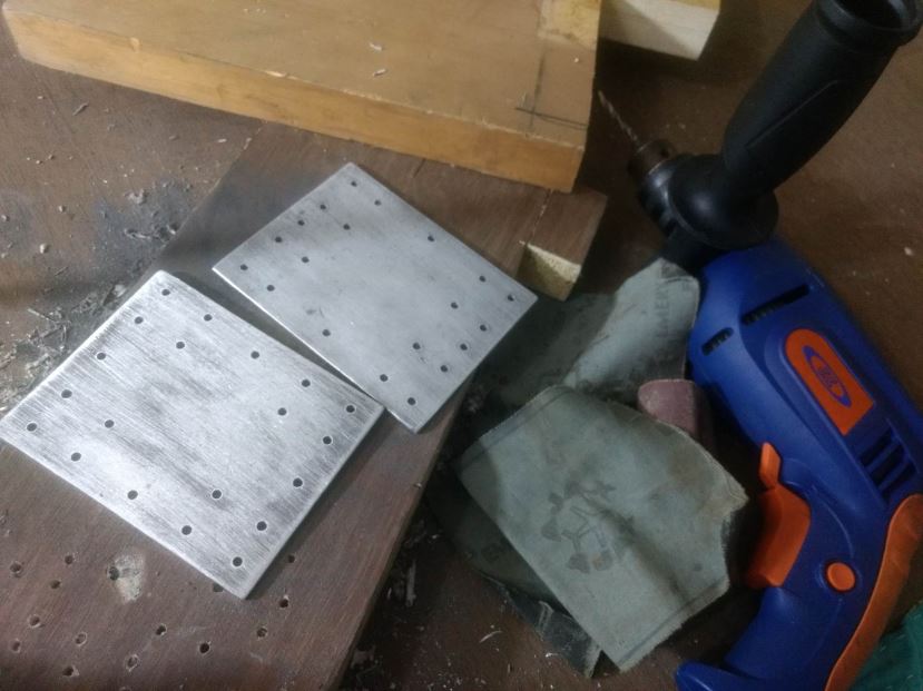
• 1 x Aluminium Sheet 3mm
• 20 x 1 Inch Screw m4
• 20 x 3 Inch Screw M4
• 1 x Inch Screw m3
• 1 x Wire 5m
• 1 x SMPS 12v 5A
• 20 x Washers M4
• 6 x 4 Inch Screw M3
• 1 x Soldering Wire
• 1 x Solder
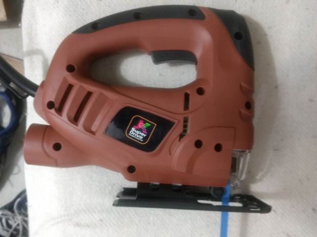
• 1 x Jig Saw
• 1 x Jig Saw Blade for wood cutting
• 1 x USB Wire
• 4 x Special Liquid ink PEN of multiple colour
• 5x Ferrite Core
• Miscellaneous Tools and Components
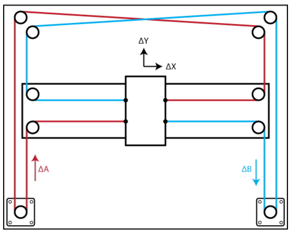
Core[X,Y]
Core[X,Y] makes things easy and have added advantage in my build. CoreXY is a technique of motion control in 2D axis using a single continuous belt for both the axes. Design Advantage: The Design of the Drawing Robot is Compact as the Y axis motor as well as X axis motor is also on the main chassis, which keeps the centre of gravity closer to the chassis. So reduces machine weight as you can now use lighter rods and mechanism on the X axis as now it doesn’t have to carry the heavy stepper motor. Fast: CoreXY believe in speed. CoreXY’s (mostly) parallel kinematics mean that the motors, typically the largest source of inertia on a DIY-grade stage, are stationary. This permits rapid accelerations. Simple: CoreXY can be implemented with only three structural plates, all of which can nest during fabrication. Flexible: Whether your medium is fabric or aluminium, the principle behind CoreXY permits motion stages to be rendered in a variety of materials and a wide range of sizes.
CoreXY Working
Building The CNC’s Body
Build Process
JK Super Drive Jig Saw Used for All Cutting
JK 13mm Drill with Al Plates
Plastic Pulleys
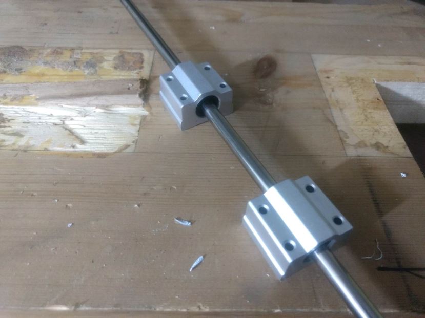
Linear Bearings with Shaft
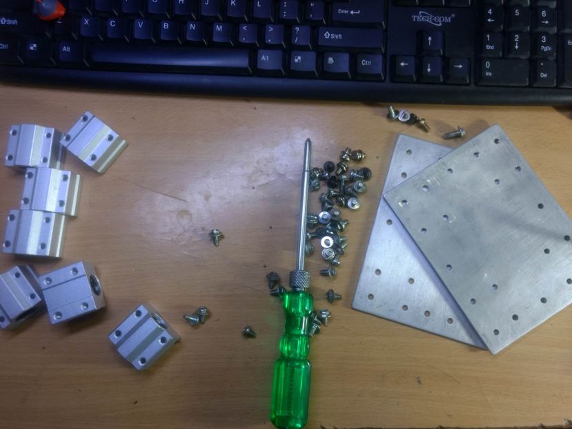
Assembling the bearings
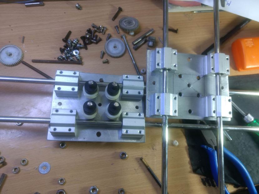
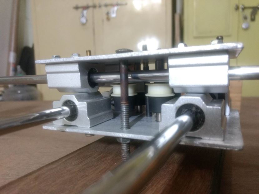
Pulleys in Central Carriage Assembly
Pulleys in Central Carriage Assembly
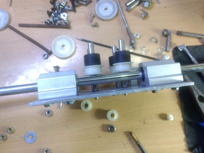
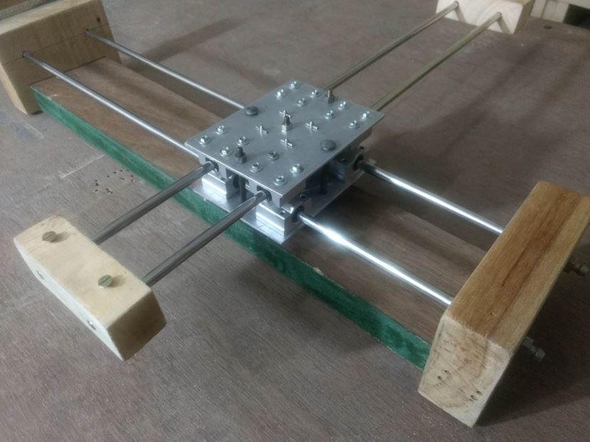
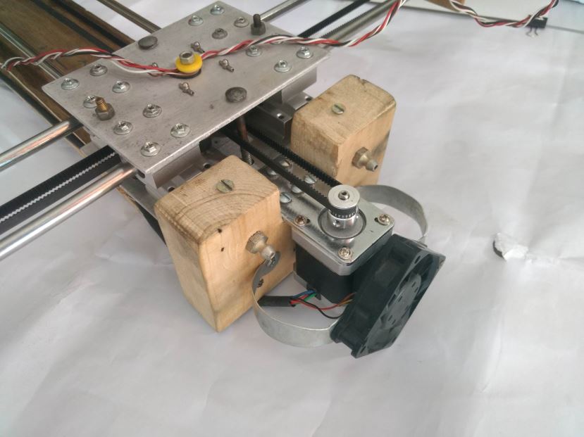
X and Y Axis Before Mounting on Chassis
X and Y Axis After Mounting on Chassis
X and Y Axis After Mounting on Chassis
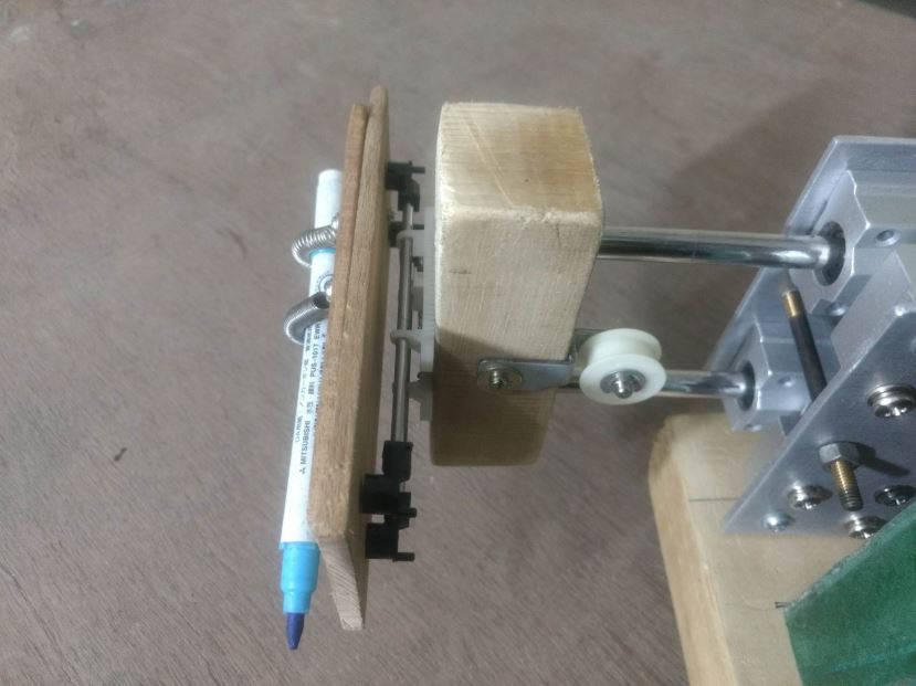
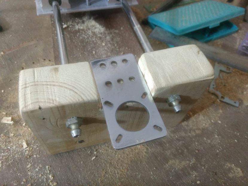
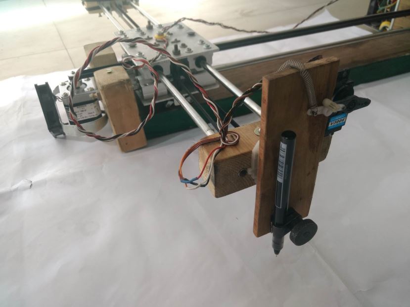
Pen Holder Bottom View
Pen Holder Components
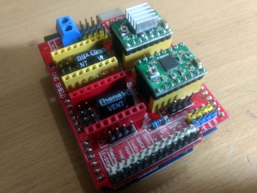
Arduino With CNC Shield
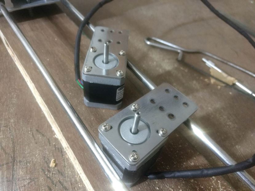
5.5Kgcm Stepper with Clamps
Stepper being Mounted on Chassis
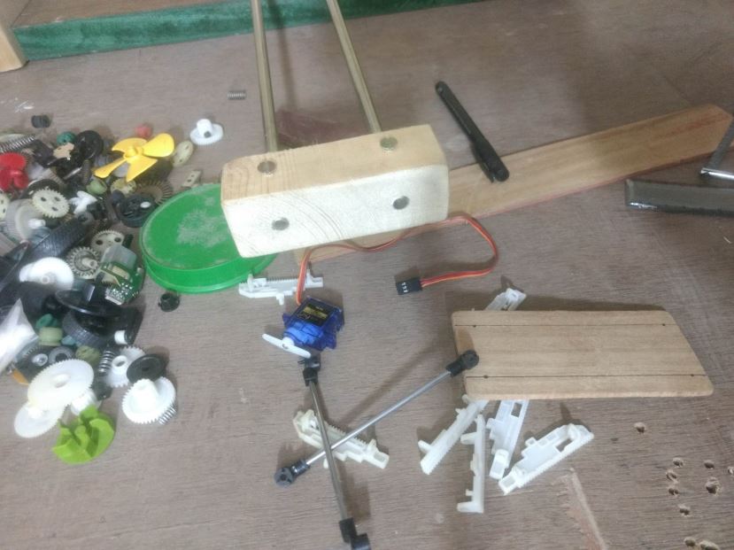
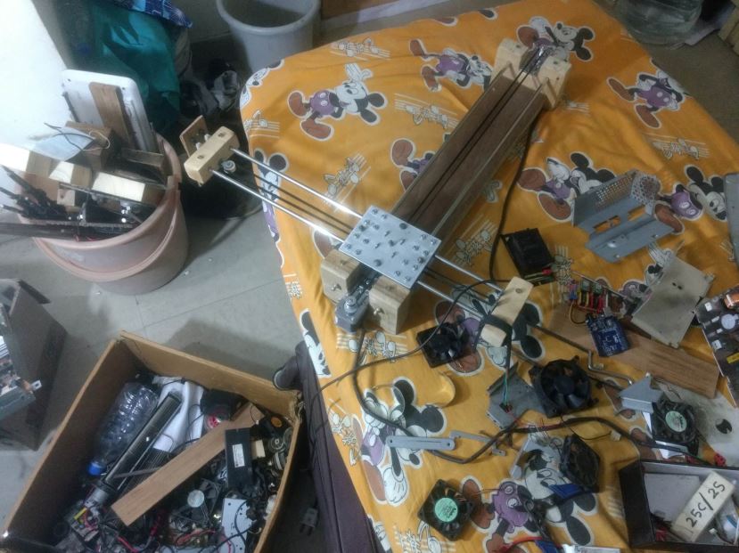
Mess During the Project Making
Raster Drawing Drawing Crazy Engineer’s Drawbot
Vector Drawing Crazy Engineer’s Drawbot
After Drawing Completion
Arduino UNO With BLDC Fans and Stepper Driver
Stepper Motor With BLDC Fan
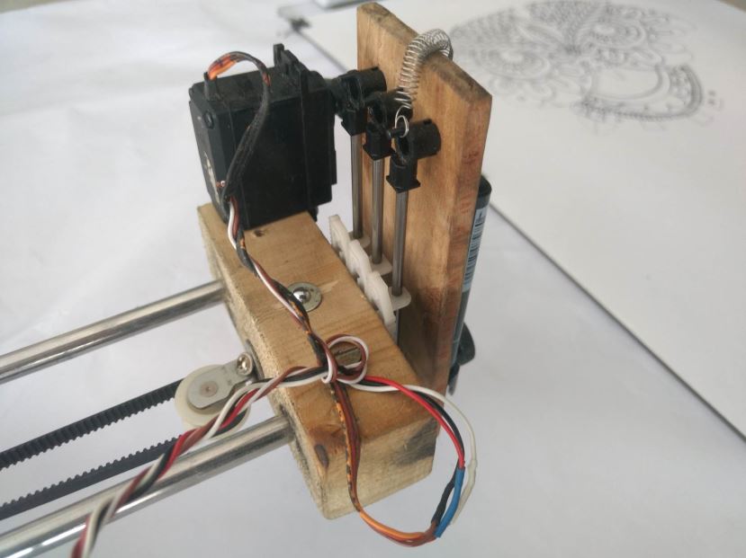
Pen Holder
Pen Holder WIth Servo Motor
Back Side of Heat Sink
Arduino Firmware Installation
This project is using a modified version of GRBL 0.9i Firmware that is . I have modified to enable CoreXY configuration and also enabled servo motor operation on pin D11. The servo motor will raise and lower the pen using Machine Code M03 and M05. (Will explain later in detail). So in Z axis no Stepper Motor is required to pull the pen.
Grbl-coreXY-servo is a no-compromise, high performance, low cost alternative to parallel-port-based motion control for CNC milling. It will run on a vanilla Arduino (Duemillanove/Uno) as long as it sports an Atmega 328p.
The controller is written in highly optimized C utilizing every clever feature of the AVR-chips to achieve precise timing and asynchronous operation. It is able to maintain up to 30kHz of stable, jitter free control pulses.
It accepts standards-compliant G-Code and has been tested with the output of several CAM tools with no problems. Arcs, circles and helical motion are fully supported, as well as, all other primary G-Code commands. Macro functions, variables, and most canned cycles are not supported, but we think GUIs can do a much better job at translating them into straight G-Code anyhow.
Grbl-coreXY-servo includes full acceleration management with look ahead. That means the controller will look up to 18 motions into the future and plan its velocities ahead to deliver smooth acceleration and jerk-free cornering.
• Licensing: Grbl is free software, released under the GPLv3 license.
After downloading you have to flash the Arduino Uno with the firmware.
Here are the Steps:
NOTE: Before starting, delete prior Grbl library installations from the Arduino IDE. Otherwise, you’ll have compiling issues! On a Mac, Arduino libraries are located in ~/Documents/Arduino/libraries/. On Windows, it’s in My Documents\Arduino\libraries.
2. Launch the Arduino IDE
• Make sure you are using the most recent version of the Arduino IDE!
3. Load Grbl into the Arduino IDE as a Library
• Click the Sketch drop-down menu, navigate to Include Library and select Add .ZIP Library.
• IMPORTANT: Select the Grbl folder inside the grbl-coreXY-servo-master folder, which only contains the source files and an example directory.
• If you accidentally select the .zip file or the wrong folder, you will need to navigate to your Arduino library, delete the mistake, and re-do Step 3.
4. Open the GrblUpload Arduino example
• Click the File down-down menu, navigate to Examples->Grbl, and select GrblUpload.
5. Compile and upload Grbl-coreXY-servo to your Arduino
• Connect your Arduino Uno to your computer.
• Make sure your board is set to the Arduino Uno in the Tool->Board menu and the serial port is selected correctly in Tool->Serial Port.
• Click the Upload, and Grbl-coreXY-servo should compile and flash to your Arduino! (Flashing with a programmer also works by using the Upload Using Programmer menu command.)
Software Tools Installation
We need multiple software and plugins for generating art-work, editing and sending G-Code to the CNC using Serial COM Port. I will be discussing installation in Windows platform but you can find all the software for Linux platform too. So the software we will be using are:
>>> Inkscape
[ Will be used to edit vector graphics and also to generate vector graphics (.svg) from .jpg, .png and .dxf formats ]
• Download the latest stable 32bit/64bit version according to your OS from Inkscape.org
• Installation is pretty simple and straight forward in Windows. In Linux you need to type some easy commands.
• Just do a Next Next and software will be installed.
>>> JTP Laser Tool Inkscape Plugin
[This Inkscape plugin will convert paths/drawing to G-Code for Vector Printing]
• Download the plugin from JTP Website
• Extract it using any good unzipping software.
• Put the contents of this .zip folder into the “inkscape\share\extensions” folder in installation directory.
• Once it is there it will show up under the “extensions” tab in Inkscape.
>>> Raster 2 Laser G-Code Generator
[This Inkscape plugin will convert paths/drawing to G-Code for Raster Printing]
• Download the plugin from my Git Hub Repository Raster 2 Laser
• Extract it using any good unzipping software.
• Put the contents of this .zip folder into the “Inkscape\share\extensions” folder in installation directory.
• Once it is there it will show up under the “extensions” tab in Inkscape.
>>> UGS Platform / UniversalGcodeSender
[ Will send G-Codes from laptop to Arduino UNO via USB Serial Port]
• Download and install the version of Java listed on the download page according to your OS and system configuration. Requires Java 8. Download Here
• Download UGS Platform UGS Download
• Extract it using any good unzipping software.
• In the extracted folders locate bin in the ugsplatform directory.
• On Windows run ugsplatform.exe or ugsplatform64.exe, on Linux or Mac OSX run ugsplatform.
• No need of any installation or build.
>>> Camotics
[ Will be used for visualizing G-Codes and simulation purpose]
• Download the latest version from Camotics
• Simple and fluid installation.
>>> Makelangelo Software
[Will be used to generate monochrome pattern art work from jpg, png and other formats that can be printed by single colour pen by CNC Drawing Machine]
• Download the Makelangelo Software from my Git Hub Repository Makelangelo-Software
• Extract it using any good unzipping software.
• Open the extracted folder and find Makelangelo10.jar file.
• Run the .jar file using Java 8 you have installed in previous steps.
>>> Inkscape Template File
[This template will be used according to the paper feeded to the Drawing Machine and will help in G-Code generation with exact dimension]
• Download the template from my Git Hub Repository Inkscape-Template
• Extract it using any good unzipping software.
• Open the extracted folder and find Makelangelo10.jar file.
Processing from Existing JPG/PNG Image in Inkscape
• Open Inkscape.
• Open the template you have downloaded in previous step according to your paper size.
• Click on File -> Import then select the JPG or PNG file from your drive and click open.
• Resize and position the image according to your page size.
• Image must be inside the boundaries of the page or G-code will not be generated properly.
• Right Click on the image and select Trace Bitmap.
• Select any of the Three Option [ Experiment and You will know the working] Brightness Cutoff, Edge Detection, Colour Quantization.
• Change the threshold according to the details you want in the drawing.
• Click on Update.
• Click OK and close the window.
• The Vector Bitmap will be overlapping the original picture.
• Drag out the original picture and delete it. You are ready to generate G-code.
• Now See G-code Generation Step.
Processing from Custom Drawing in Inkscape
• Open Inkscape.
• Open the template you have downloaded in previous step according to your paper size.
• Start drawing or writing text inside the work area.
• Select all the objects by Ctrl+A shortcut.
• Group then together by Object -> Group from menu or by Ctrl+G shortcut.
• Then you have to convert object to path from menu Path -> Object To Path or by shortcut Shift+Ctrl+C. [ Important Step]
• Now See G-code Generation Step.
Generating Art Work from Image in Makelangelo Software
• Open Makelangelo Software running the .jar file.
• Click Open File and select the JPG/PNG file from your drive.
• Select the Conversion Style from the drop down menu. [ My fav is Crosshatch]
• Click ok.
• Click Save to file/SD Card and go to the location where you want to save.
• Put your file name and select DXF R12 File Format .DXF.
• Now run Inkscape and open the saved .DXF file with default settings.
• Resize it according to your need.
• Now See G-code Generation Step.
Raster G-code Generation
• In raster mode the machine will scan the whole drawing area from [0,0] till the end line by line. [Raster mode is slow and takes more time]. See the videos [Raster Drawing Girl’s Face Video 1] [Raster Drawing Girl’s Face Video 2]
• After converting all objects to path from previous step you are ready to generate your G-code.
• Now select all the paths that are inside the work area or use Ctrl+A.
• Click Extensions -> 305 Engineering -> Raster 2 Laser G-code Generator.
• Give Export Directory Path.
• Give File Name.
• Enable Numeric Suffix.
• Resolution means number of lines per mm, increasing will increase drawing time.
• Play with the options below like the RGB threshold.
• Set Engraving speed to 1500 or above.
• Select No Homing.
• Edit Laser ON to M03 S255.
• Edit Laser OFF to M05 S0.
• Deselect Preview, if selected no G-code will be generated.
• Click Apply. Wait and Enjoy. You are Ready to print now.
Vector G-code Generation
• In vector mode the machine will scan the only the drawing area where lines are there. [Vector mode drawing takes less time]. See the video [Vector Drawing PowerPuff Girls Video ]
• After converting all objects to path from previous step you are ready to generate your G-code.
• Now select all the paths that are inside the work area or use Ctrl+A.
• Click Extensions -> Generate laser G-code -> J Tech Photonics Laser Tool.
• Give Export Directory Path.
• Give File Name.
• Enable Numeric Suffix.
• Set All Units to mm.
• Set Laser speed to 1500 or above.
• Set Travel speed to 3000 or above.
• Select No Homing.
• Edit Laser ON to M03.
• Edit Laser OFF to M05.
• Deselect Preview
• Click Apply. Wait and Enjoy. You are ready to Print now.
GRBL Configuration and Setting Up Your Machine for the First Time
First, connect to Grbl using the serial terminal of your choice.
Set the baud rate to 115200 as 8-N-1 (8-bits, no parity, and 1-stop bit.)
Once connected you should get the Grbl-prompt, which looks like this:
Grbl 0.9i [‘$’ for help]
Type $ and press enter to have Grbl print a help message. You should not see any local echo of the $ and enter. Grbl should respond with:
The ‘$’-commands are Grbl system commands used to tweak the settings, view or change Grbl’s states and running modes, and start a homing cycle. The last four non-‘$’ commands are realtime control commands that can be sent at anytime, no matter what Grbl is doing. These either immediately change Grbl’s running behavior or immediately print a report of the important realtime data like current position (aka DRO).
$$ – View Grbl settings
To view the settings, type $$ and press enter after connecting to Grbl. Grbl should respond with a list of the current system settings, as shown in the example below. All of these settings are persistent and kept in EEPROM, so if you power down, these will be loaded back up the next time you power up your Arduino.
$x=val – Save Grbl setting
The $x=val command saves or alters a Grbl setting, which can be done manually by sending this command when connected to Grbl through a serial terminal program, but most Grbl GUIs will do this for you as a user-friendly feature.
To manually change e.g. the microseconds step pulse option to 10us you would type this, followed by an enter:
$0=10
If everything went well, Grbl will respond with an ‘ok’ and this setting is stored in EEPROM and will be retained forever or until you change them. You can check if Grbl has received and stored your setting correctly by typing $$ to view the system settings again.
Grbl’s default configuration is intentionally very generic to help ensure users can see successful motion without having to tweak settings. Generally, the first thing you’ll want to do is get your stepper motors running, usually without it connected to the CNC. Wire Grbl to your stepper drivers and stepper motors according to your manufacturer guidelines. Connect to Grbl through a serial terminal or one of many Grbl GUIs. Send some G1 or G0 commands to Grbl. You should see your stepper motor rotating. If you are having trouble with your stepper motors, try the following:
• Ensure everything is wired and powered correctly per your stepper driver manufacturer guidelines.
• If your steppers are mounted in your CNC already, ensure your axes move freely and don’t obviously bind. If you can’t easily tell, try removing your steppers and check if they run under no load.
• Ensure your stepper motors and axes linear mechanisms are all tight and secure. Small set screws on drivetrain components becoming loose is a very common problem. Re-tighten and try applying some non-permenant thread locker (Loctite blue) if it continually loosens.
• For more difficult issues, try the process of elimination to quickly isolate the problem. Start by disconnecting everything from the Arduino. Test if Grbl is operating ok by itself. Then, add one thing at a time and test.
• If your steppers are powered and making a grinding noise when trying to move, try lowering the ‘$’ acceleration and max rate settings. This sound is a sign that your steppers is losing steps and not able to keep up due too much torque load or going too fast.
• Grbl’s default step pulse settings cover the vast majority of stepper drivers on the market. While very uncommon, check these settings if you are still experiencing problems or have a unusual setup.
Next, you will need to make sure your machine is moving in the correct directions according to a Cartesian(XYZ) coordinate frame. Mount your stepper motors into your CNC, if you haven’t already done so. Send Grbl some motion commands, such as G91 G0 X1 or G91 G0 X-1, which will move the x-axis +1mm and -1mm, respectively. Check all axes. If an axis is not moving correctly, alter the $3 direction port mask setting to invert the direction.
If you are unfamiliar with how coordinate frames are setup on CNC machines, see this great diagram by LinuxCNC. Just keep in mind that motions are relative to the tool. So on a typical CNC gantry router, the tool will move rather than the fixed table. If the x-axis is aligned positive to the right, a positive motion command will move the tool to the right. Whereas, a moving table with a fixed tool will move the table to the left for the same command, because the tool is moving to the right relative to the table.
Finally, tune your settings to get close to your desired or max performance. Start by ensuring your $100,$101, and $102 axes step/mm settings are correct for your setup. This is dependent on your stepper increments, micro steps on your driver, and mechanical parameters. There are multiple resources online to show you how to compute this for your particular machine, if your machine manufacturer has not supplied this for you. Tweak your $11x acceleration and $12x max rate settings to improve performance. Set to no greater than 80% of absolute max to account for inertia and cutting forces. Set your $13x max travel settings if you plan on using homing or soft limits. It’s recommended to enter something approximately close to actual travel now to avoid problems in the future.
At this point, you’re pretty much ready to get going! Grbl can now move your CNC machine and run g-code jobs. If you need to add more features, such as limit switches for homing or hard limits or spindle/laser control. There are other Wiki pages to help you that. Good luck and have fun!
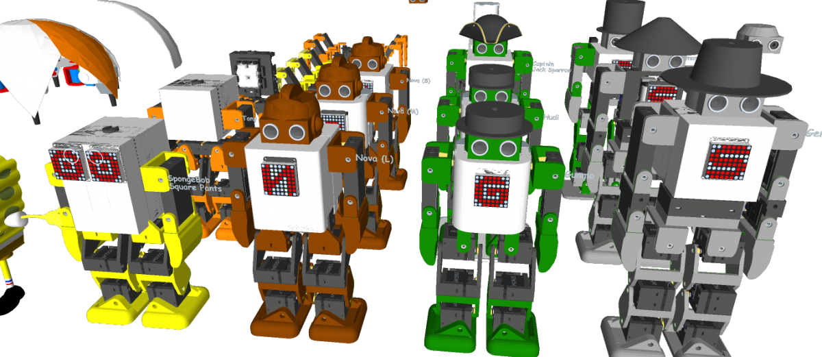
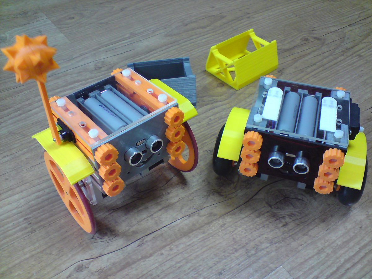
Robonoid is small sized bipedal walking robot The robot has 17 or 19, 24 freely moveable joints and servomotor in order to provide for a range of action and stable movements. Since it’s small in size, Robonoid can balance well and cope with basic movements such as walking and getting up. Also, intricate movements like roller skating and skateboarding are possible.
Robonoid is a wireless controllable robot You can control it by WiFi protocol through your PC and Smartphones. App for android and iOS are an especially intelligible UI. By using it, complicated operations can be controlled more easily.
Robonoid is a friendly robot Robonoid was named indicates a “simply shaped robot” that everyone imagines. Robonoid was designed by pursuing a simple appearance and simple functionality.
PSY – 135.7mm(W) x 258.39mm(H) x 100mm(D) – 17DOF
Jack – 135.7mm(W) x 305.62mm(H) x – 92,48mm(D) – 22DOF
Gentleman – 135.7mm(W) x 341.22mm(H) x – 78.5mm(D) – 22DOF
Tony – 135.7mm(W) x 265.5mm(H) x – 100mm(D) – 18DOF
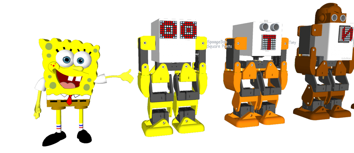
SpongwBob – 135.7mm(W) x 230.0mm(H) x 100mm(D) – 16DOF
Hudi – 135.7mm(W) x 251.4mm(H) x 87mm(D) – 19DOF
Gunmo – 135.7mm(W) x 259.3mm(H) x 78.5mm(D) – 19DOF – https://youtu.be/qIZJZDcRpVw
Nova – 135.7mm(W) x 282.8mm(H) x 100mm(D) – 17DOF – https://youtu.be/kzfyKRzp_9I
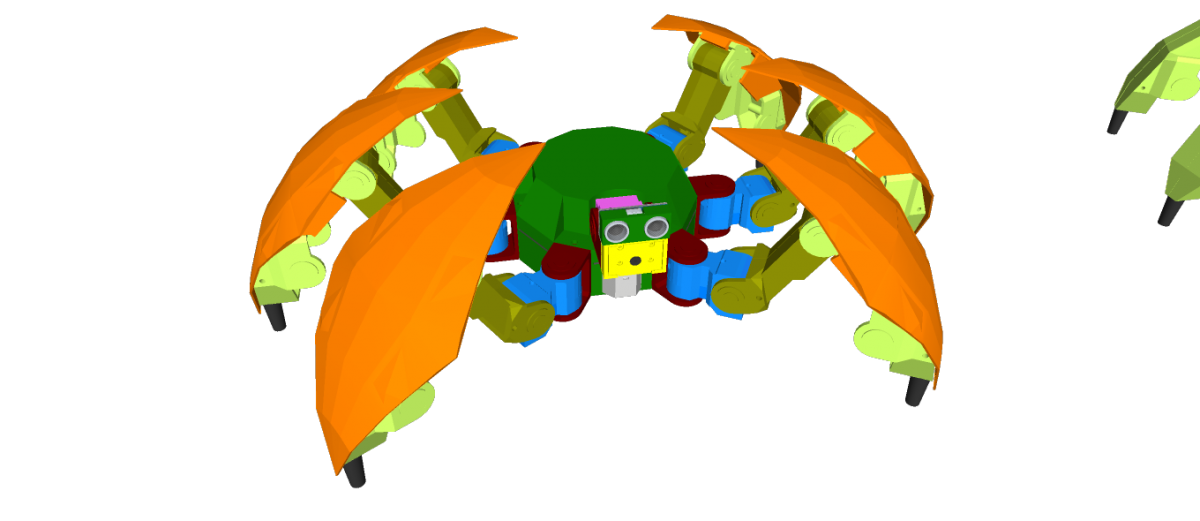
Hexapod S1 – DOM 352.83mm(WD) x 193.16mm(H) – 20DOF
Robonoid is a Plen/mini-Plan/RoboHero robot derivative designed at Zalophus DesignHouse. We love the Plen2 robot but its want to new design. This is our take on a new lower cost version of the Plen2 robot using MG90S/ES08MA-II/SG90 servo’s.
The 3D printing parts were inspired by the Plen2 components, but they were redrawn from SketchUp to use the inexpensive MG90S servo motors.
Electronic Parts
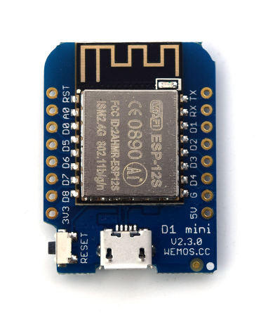
1 x WeMos D1 mini ESP8266 ESP-12
1 x PCA9685 16-channel, 12-bit PWM Fm+ I2C-bus Servo controller
1 x Shield Robonoid-20CH-R0a
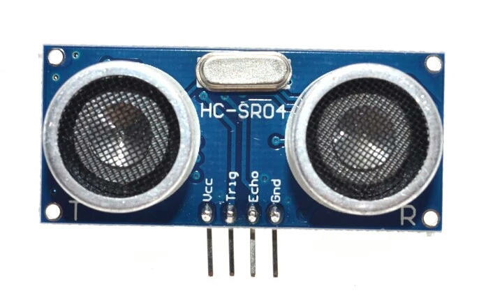
1 x HC-SR04 Ultrasonic Distance Measurement Sensor
2 x 16340 or 18650 Battery Holder
1 x 2S 7.4V Lithium Battery Charger Protection Board
2 x 16340 or 18650 Batteries
2 x Snap-In Single ‘A’-‘AA’ Battery Contacts 209 [KEYSTONE ELECTRONICS CORP.]
2 x Snap-In Single ‘A’-‘AA’ Battery Contacts 228 [KEYSTONE ELECTRONICS CORP.]
1 x DC Jack and Battery Harness Cable
17/19 x MG90S Metal Gear Servo Motors
The open source Humanoid Robot – Robonoid hardware and software is free and made with love. Please show your level of support with a voluntary donation.
Robonoid is small sized bipedal walking robot
The robot has 20 freely moveable joints and servomotor in order to provide for a range of action and stable movements. Since it’s small in size, Robonoid can balance well and cope with basic movements such as walking and getting up. Also, intricate movements like roller skating and skateboarding are possible.
Robonoid is a wireless controllable robot
You can control it by WiFi protocol through your PC and Smartphones. App for android and iOS are an especially intelligible UI. By using it, complicated operations can be controlled more easily.
Robonoid is a friendly robot
Robonoid was named indicates a “simply shaped robot” that everyone imagines. Robonoid was designed by pursuing a simple appearance and simple functionality.
Robonoid Lineup
– Papi – 28DOF
– S6 – 20DOF
– S4 – 14DOF
– PSY – 135.7mm(W) x 258.39mm(H) x 100mm(D) – 17DOF
– Jack – 135.7mm(W) x 305.62mm(H) x – 92,48mm(D) – 22DOF
– Gentleman – 135.7mm(W) x 341.22mm(H) x – 78.5mm(D) – 22DOF
– Tony – 135.7mm(W) x 265.5mm(H) x – 100mm(D) – 18DOF
– SpongwBob – 135.7mm(W) x 230.0mm(H) x 100mm(D) – 16DOF
– Hudi – 135.7mm(W) x 251.4mm(H) x 87mm(D) – 19DOF
– Gunmo – 135.7mm(W) x 259.3mm(H) x 78.5mm(D) – 19DOF
– Nova – 135.7mm(W) x 282.8mm(H) x 100mm(D) – 17DOF
– M1 – 180.7mm(W) x 350.74mm(H) x 110mm(D) – 24DOF
– Hexapod H1 – DOM 352.83mm(WD) x 193.16mm(H) – 20DOF
Robonoid is a Plen/mini-Plan/RoboHero robot derivative designed at Zalophus DesignHouse. We love the Plen2 robot but its want to new design. This is our take on a new lower cost version of the Plen2 robot using ES08MA-II/SG90 servo’s.
The 3D printing parts were inspired by the Plen2 components, but they were redrawn from SketchUp to use the inexpensive MG90S servo motors.
Electronic Parts
– 1 x WeMos D1 mini ESP8266 ESP-12
– 1 x PCA9685 16-channel, 12-bit PWM Fm+ I2C-bus Servo controller
– 1 x Robonoid-20CH-R0a Shield
– 1 x HC-SR04 Ultrasonic Distance Measurement Sensor
– 2 x 16340 Battery Holder
– 1 x 2S 7.4V Lithium Battery Charger Protection Board
– 2 x 16340 Batteries
– 1 x DC Jack and Battery Harness Cable
– 20 x ES08MA-II Metal Gear Servo Motors
The open source Humanoid Robot – Robonoid hardware and software is free and made with love. Please show your level of support with a voluntary donation.
Robonoid is small sized bipedal walking robot The robot has 17 or 19, 24 freely moveable joints and servomotor in order to provide for a range of action and stable movements. Since it’s small in size, Robonoid can balance well and cope with basic movements such as walking and getting up. Also, intricate movements like roller skating and skateboarding are possible.
Robonoid is a wireless controllable robot You can control it by WiFi protocol through your PC and Smartphones. App for android and iOS are an especially intelligible UI. By using it, complicated operations can be controlled more easily.
Robonoid is a friendly robot Robonoid was named indicates a “simply shaped robot” that everyone imagines. Robonoid was designed by pursuing a simple appearance and simple functionality.
PSY – 135.7mm(W) x 258.39mm(H) x 100mm(D) – 17DOF
Jack – 135.7mm(W) x 305.62mm(H) x – 92,48mm(D) – 22DOF
Gentleman – 135.7mm(W) x 341.22mm(H) x – 78.5mm(D) – 22DOF
Tony – 135.7mm(W) x 265.5mm(H) x – 100mm(D) – 18DOF
SpongwBob – 135.7mm(W) x 230.0mm(H) x 100mm(D) – 16DOF
Hudi – 135.7mm(W) x 251.4mm(H) x 87mm(D) – 19DOF
Gunmo – 135.7mm(W) x 259.3mm(H) x 78.5mm(D) – 19DOF – https://youtu.be/qIZJZDcRpVw
Nova – 135.7mm(W) x 282.8mm(H) x 100mm(D) – 17DOF – https://youtu.be/kzfyKRzp_9I
Hexapod S1 – DOM 352.83mm(WD) x 193.16mm(H) – 20DOF
Robonoid is a Plen/mini-Plan/RoboHero robot derivative designed at Zalophus DesignHouse. We love the Plen2 robot but its want to new design. This is our take on a new lower cost version of the Plen2 robot using MG90S/ES08MA-II/SG90 servo’s.
The 3D printing parts were inspired by the Plen2 components, but they were redrawn from SketchUp to use the inexpensive MG90S servo motors.
Electronic Parts
1 x WeMos D1 mini ESP8266 ESP-12
1 x PCA9685 16-channel, 12-bit PWM Fm+ I2C-bus Servo controller
1 x Shield Robonoid-20CH-R0a
1 x HC-SR04 Ultrasonic Distance Measurement Sensor
2 x 16340 or 18650 Battery Holder
1 x 2S 7.4V Lithium Battery Charger Protection Board
2 x 16340 or 18650 Batteries
2 x Snap-In Single ‘A’-‘AA’ Battery Contacts 209 [KEYSTONE ELECTRONICS CORP.]
2 x Snap-In Single ‘A’-‘AA’ Battery Contacts 228 [KEYSTONE ELECTRONICS CORP.]
1 x DC Jack and Battery Harness Cable
17/19 x MG90S Metal Gear Servo Motors
The open source Humanoid Robot – Robonoid hardware and software is free and made with love. Please show your level of support with a voluntary donation.
If you have further questions or ideas to perfect my design, please feel free to comment 🙂
Watch it draw:
And the idea of the penholder, as video:
Step 1: GENERAL_ COMPONENTS BOM
BILL OF MATERIALS
(all prices like i paid on amazon)
2 stepper motors 2×25$
I used NEMA8 and NEMA17. Both work well, the 8beeing a quarter of the size of the 17.
If you want to get an idea for the numbers of NEMA steppers, its 1/10 of the distance between two nearby mounting holes. In inches.
So in a NEMA 8 motor, the mounting holes are placed on an 0,8″x0,8″ square. Pretty tiny.
Stepper motor drivers 30$ from adafruit or 8$ clone
As i used the Makelangelo firmware, i used an Adafruit Motorshield v1 (clone)
Makelangelo runs with(out modification) on an Uno with AMShield v1 and v2, and with a MEGA 2560 and the RAMPS 1.4 shield.
I tested the uno with v1 and the RAMPS setup, both work.
Micro servo or Solenoid 5$ each
Both work, the solenoid is the more elegant option, but needs some tweaks to the firmware.
You can take virtually any servo available.
On my penholder, i use a standard 5$ microservo, as you can see on some photos.
Belt/Chain 12$ (see dedicated step)
The cheaper and more elgant version is the belt.
I still used white pearlropes from home depot first, because i didnt know that 5m belt with 5 pulleys are 12$ on amazon.
Pens (see dedicated steps)
It sucks pens dry like nothing, so ballpens are the most efficient, copics the most expensive
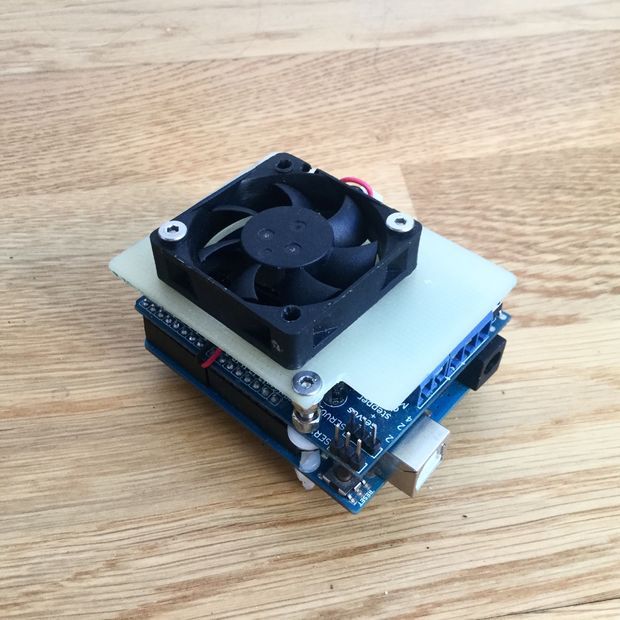
Step 2: ELECTRONICS_ ADAFRUIT SHIELD ARDUINO
I used an Arduino (Genuino) UNO, but ordered a feather M0 with a stepperwing, to make it more compact.
There isnt any special thing to consider, just plug the shield to the arduino and give it the code 🙂
On thing i found out is, the L284 drivers get really really hot, so if they didnt came with heatsinks, better add some, or mount a fan like i did.
Probably both, depending on the motors/weight.
To mount the cooling fan i took a sheet of 3mm fibreglass and cut it with a jigsaw.
The fan is pretty strong and loud, i probably add a pot in the future to tune it down a bit.
Step 3: MECHANICS_ BELTS ROPES PEARL-ROPES
Basically there are three systems.
Beginning with the worst possible version:
A spindle and some rope.
The problem is, that with spooling of the rope, the spindle-diameter changes, so the calculation isnt correct anymore, which ends in wacky drawings.
A Pearlchain from window-shutters.
Very light and precise setup. I have built a big plotter for shop windows and liquid chalk that uses two 3m ropes.
The problem with the rope and the pearls is, that it needs special idler pulleys if you wanna use idler pulleys at all.
A belt from 3d printing spares
To me the best and most affordable version is a 5mm belt. As i wrote earlier i bought 5m of belt together with five teeth pulley for 12$ on amazon.
Its super precise, though i think it flexes more then the rope.
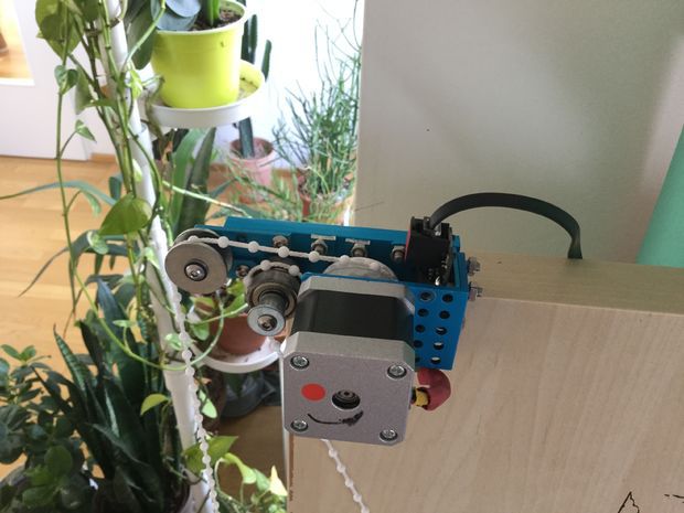
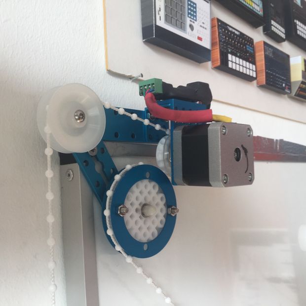
Step 4: MECHANICS_ STEPPERS MOUNTS IDLER-PULLEYS
The easiest and cleanest version is to just mount a teeth pulley on the motor and let it go.
Be sure to add some counterweight, to prevent slip.
If you want or need to make it more complex, i added some photos, that solve different problems i had at that time.
On the NEMA17 stepper photos:
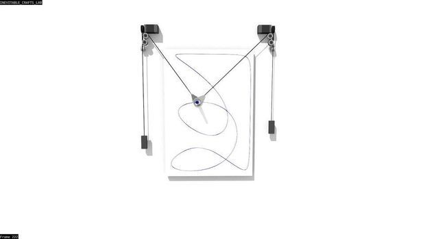
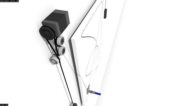
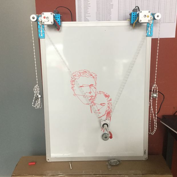
One thing i always tried to do was to keep distance between the left and right idler pulley as wide as possible.
In a polar v plotter, one situation that is sub-optimal is, when one of the belts hangs down vertically.
Thats the position where the motors have the least control about what the pen is doing.
I tried to avoid that, by mounting the last idler pulleys wider then the canvas.
Next i had to mount a second idler to get the counterweight out of the line.
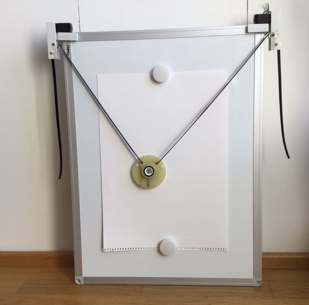
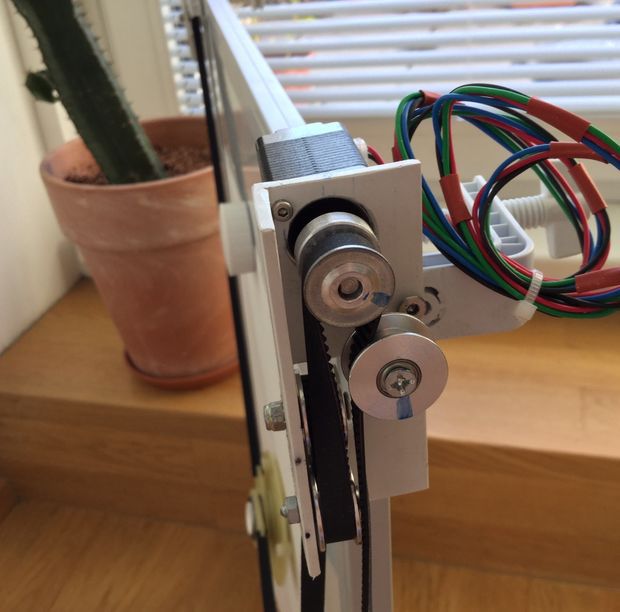
On the NEMA 8 photo:
This will be a small A3 version, that hangs on the wall, framed, and takes portrait of random people.
O the goal was to make it as flat as possible. As you can see there is one 90degree twist in the belt to get the motor parallel to the wall.
All idlers have double ball bearings and run supersmooth
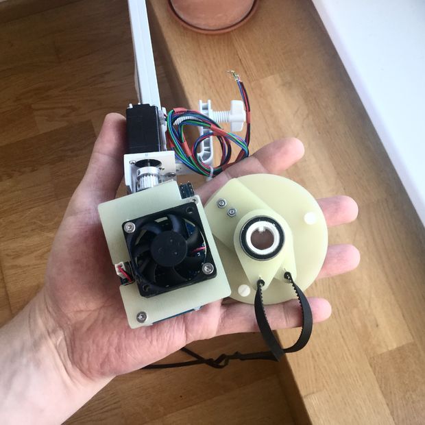
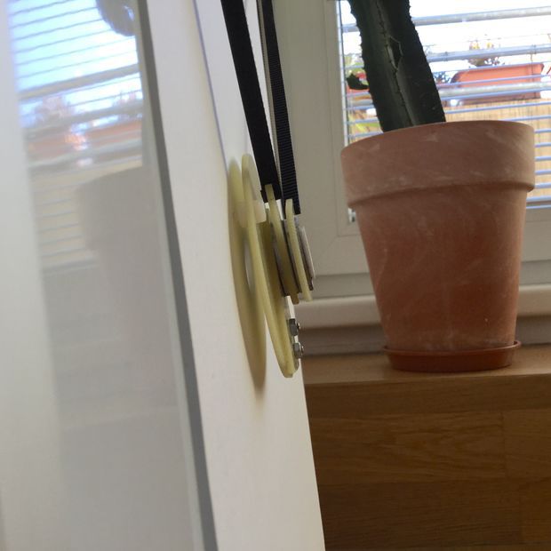
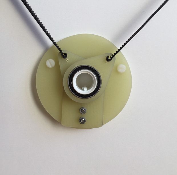
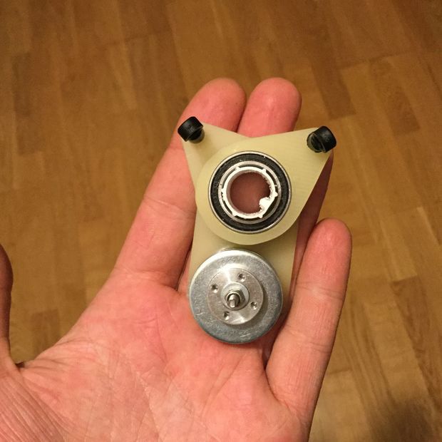
Step 5: MECHANICS_ PEN GONDOLA
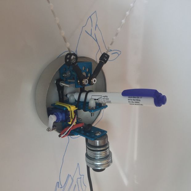
There are endless versions how to mount a pen and lift a pen hanging on two ropes.
The blue penholder on the photos is made from a segafredo coffeecan some makeblock parts and a servo.
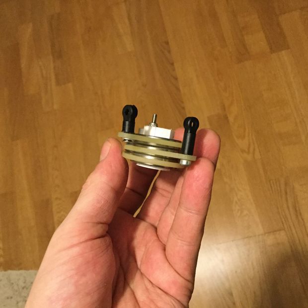
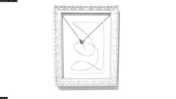
The second (yellow) version is made for endless-lines drawings (without lifting) and is made of three ballbearings and three 3mm fibreglass parts.
If anyone is interested in the second design, i will get a 3d printer very soon, and can add a 3d file as soon as i tested/printed it on my printer.
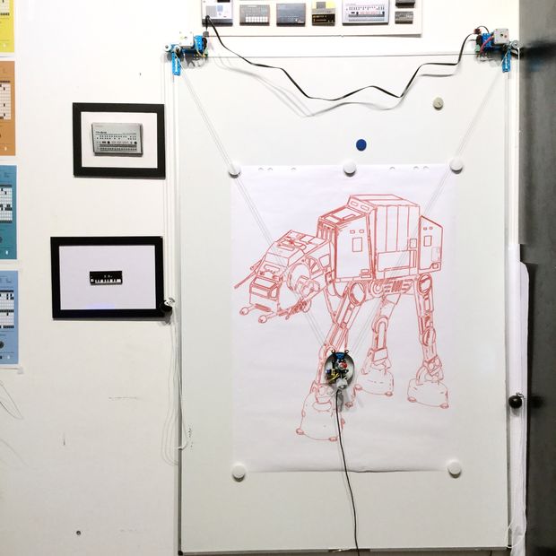
I would say there are three classic surfaces for a plotter like that:
First the surface where the polar v plotter is the only plotter capeable to draw on:
Shopwindows/ windows in general
For drawing on windows, besides mirroring the graphics (which Makelangelo can do in the software) you need suction cups/glasslifters and liquid chalk pens.
Liquid chalk seems to be some sort of chemical substance that you can paint on windows with and easily wipe it of to clean the windows.
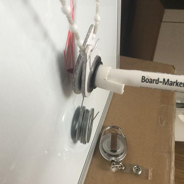
Its filled in a regular boardmarker sized pen.
Whiteboards
Also easily removable and a perfect surface to permanently mount a drawbot.
you can test directly on the whiteboard without wasting paper, and once it runs smooth, just use four magnets and put a paper on it.
Paper in general, obviously
The rougher the paper surface, the better.
The less preassure a pen needs to write, the better.
Even if the pen holder is heavy, it puts a very tiny force on the actual drawing surface.
You can always add force, by tilting the surface backwards.
On the big whiteboard plotter i mounted in my office i lifted the base of the whiteboard by 2″/5cm to get some angle.
Step 7: SOFTWARE_ MAKELANGELO
That’s pretty straight forward, just visit their site, and download the files.
Dont forget to contribute a bit, so they can keep on developing fine software like Makelangelo
The code, and java is well documented, so i wont discuss it in detail.
Step 8: GENERAL_ WHAT ABOUT …
Some ideas, what to do with a plotter like that, and how i use it.
On a whiteboard in the office
I work for a creative school and i got it in my office, to plot svg files graphic design students made, or print other stuff i would normally write on it, like xls sheets etc
With a laser-head on wooden doors, print foilage on hunterstands etc
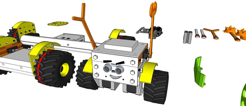
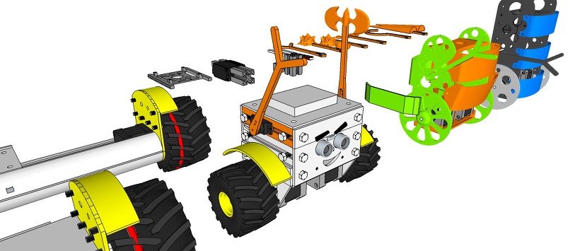
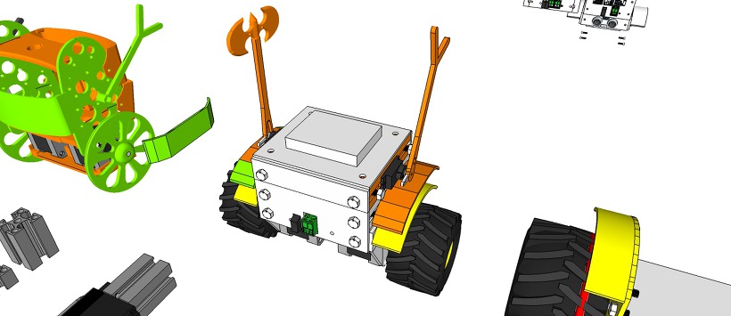
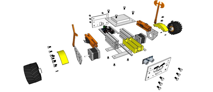
6 x ProfileBlock™ DF 2020 85mmAcrylic Plate (t = 3mm)1 x Top Plate1 x Bottom Plate
2 x Step Motor Mount Plate
1 x Front Plate
1 x Rear Plate3D Printing Parts
2 x Servo Mount ProfoleBlock
12 x Knob M5 Hexaheard
2 x Wheels 100mm or Inline Wheels 70mm(with 2 x Inline Wheels Hub)
2 x Tire Mudguards
1 x Stand1 x Battery Holder
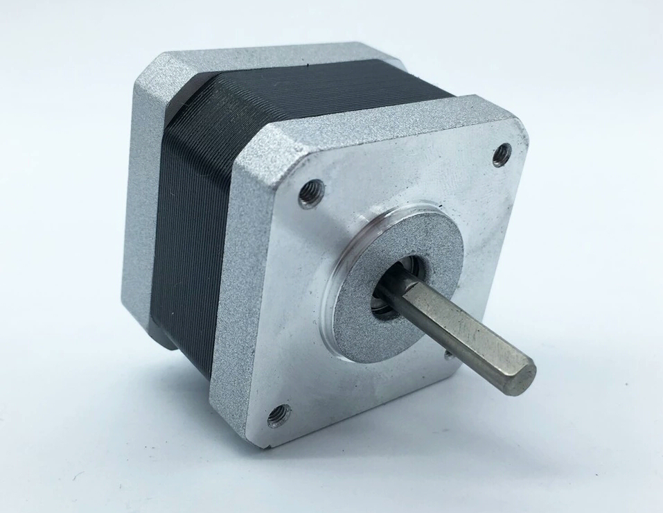
Step Motor:
2 x Nema 17 Stepper Motor bipolar 4 leads 34mm 12V 1.3A 26Ncm(36.8oz.in) 3D printer motor 42SHD0001
2 x NEMA 17 – Phase: 4, Step Angle: 1.8 Deg/Step, Holding Torque: 2.6Kg.cm
Servo:
1 x Standard Servo or SG90 Metal Servo
1 x Standard Servo (Option) or SG90 Metal Servo
12 x M5 10mm Nylon Bolts
12 x M5 8mm Nylon Bolts
12 x M5 Nylon Nuts
8 x M3 8mm Bolts
4 x M3 10mm Bolts
4 x M3 15mm Bolts
8 x M3 Nuts
Electrical______
Control Board:
1 x ESP8266 Witty Cloud or WeMos (eX-Robot)
1 x HC-SR04 ultra sonic module
1 X MPU6050
2 x A4988 Step Motor Drive
1 x LM1117-5.0 5,0V 1A Regulator
1 x LM1117-3,3 3,3V 1A Regulator
6 x 100uF 25V Capacitor
4 x 0.1uF Capacitor
1 x 220KOhm Resistor
1 x 100KOhm Resistor
4 x 10KOhm Resistor
7 x 8P Female Pin Header Connector 2.54mm Pitch
3 x 4P Male Pin Header Connector 2.54mm Pitch
2 x 3P Male Pin Header Connector 2.54mm Pitch
3 x 2P Male Pin Header Connector 2.54mm Pitch
1 x 2EDGK 5.08mm 2P Plug-in terminal connectors set
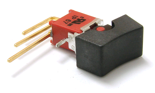
1 x Right Angle SPDT 4 Pin On-On I/O Boat Rocker Switch
1 x Interface Mother boardPower Requirements:8.4VDC
12 VDCBattery:2 x 18650 Litum Ion Battery = 7.2 VDC ~ 8.4 VDCSoftware:
ESP8266 WeMos D1 mini code: Coming soon…
WiFi UDP Control TouchOSC Layout file: Coming soon…
Arduino IDE (ESP8266 ESP-12E/F)Support SoftAP and StationSupport OTA (at Local network)Support mDNS (at Local network)
The open source ProfileBlock hardware and software is free and made with love. Please show your level of support with a voluntary donation.
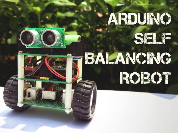
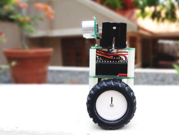
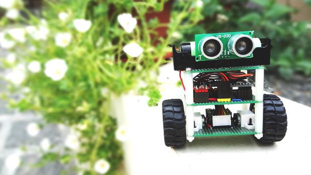
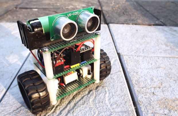
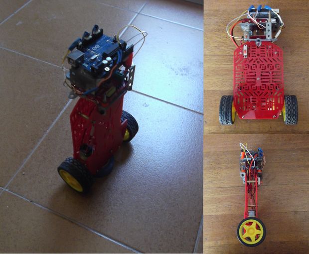
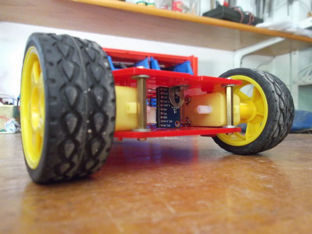
In this instructable, I’ll show you how to build a small self-balancing robot that can move around avoiding obstacles. This is a tiny robot measuring 4 inches wide and 4 inches tall and is based on the Arduino Pro Mini development board and the MPU6050 accelerometer-gyroscope module.
In the steps that follow, we will see how to interface the MPU6050 with Arduino, how to measure the angle of inclination of the robot, how to use PID to make the robot stay balanced. An ultrasonic rangefinder is also added to the robot which prevents it from banging into obstacles as it wanders around.
Parts List
I bought most of these parts from aliexpress but you can find them in any other electronics store as well.
Apart from the above, you will need some cables, berg connectors and one on/off switch.
Step 1: A Bit of Theory
Let’s start with some fundamentals before getting our hands dirty.
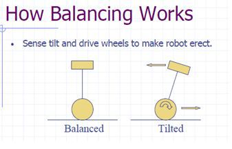
The self-balancing robot is similar to an upside down pendulum. Unlike a normal pendulum which keeps on swinging once given a nudge, this inverted pendulum cannot stay balanced on its own. It will simply fall over. Then how do we balance it? Consider balancing a broomstick on our index finger which is a classic example of balancing an inverted pendulum. We move our finger in the direction in which the stick is falling. Similar is the case with a self-balancing robot, only that the robot will fall either forward or backward. Just like how we balance a stick on our finger, we balance the robot by driving its wheels in the direction in which it is falling. What we are trying to do here is to keep the center of gravity of the robot exactly above the pivot point.
To drive the motors we need some information on the state of the robot. We need to know the direction in which the robot is falling, how much the robot has tilted and the speed with which it is falling. All these information can be deduced from the readings obtained from MPU6050. We combine all these inputs and generate a signal which drives the motors and keeps the robot balanced.
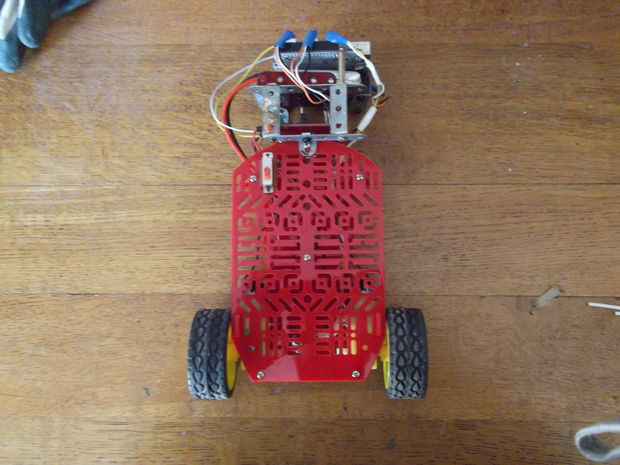
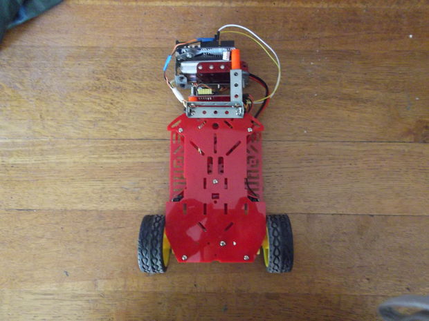
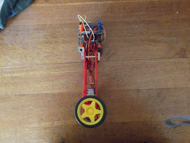
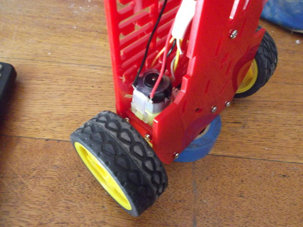
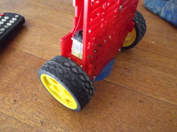
Step 2: Let’s Start Building
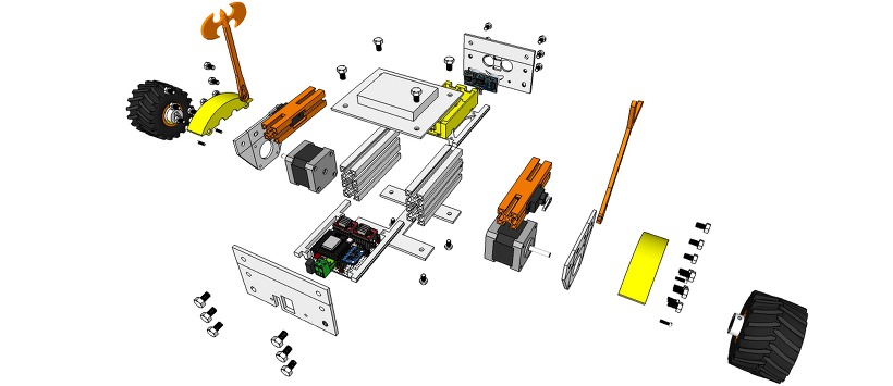
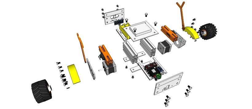
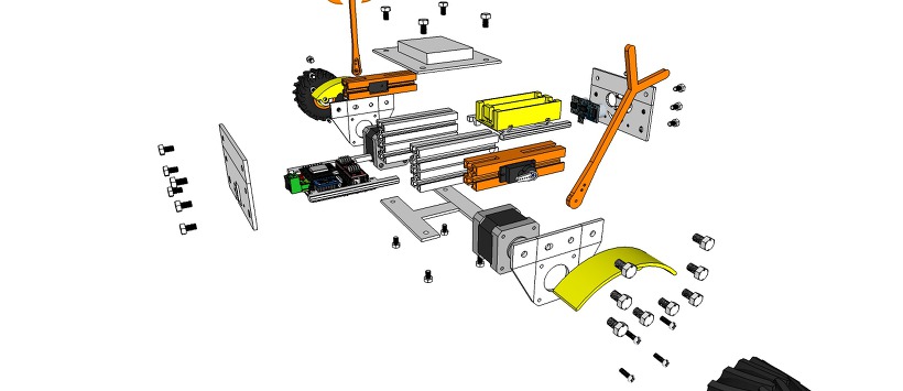
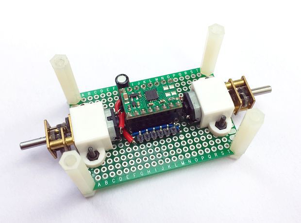
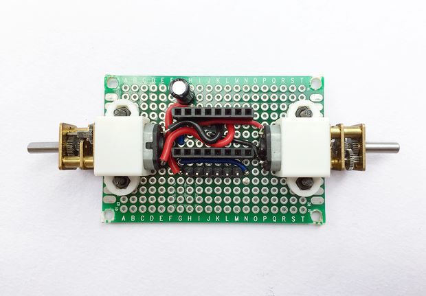
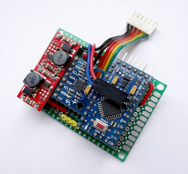
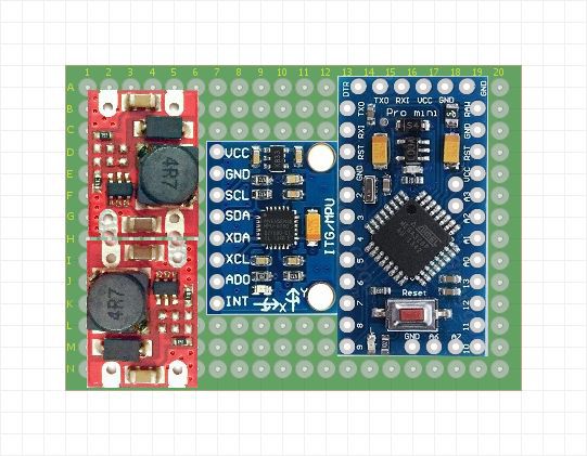
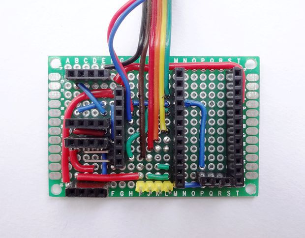
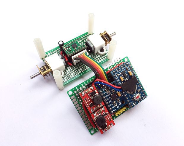
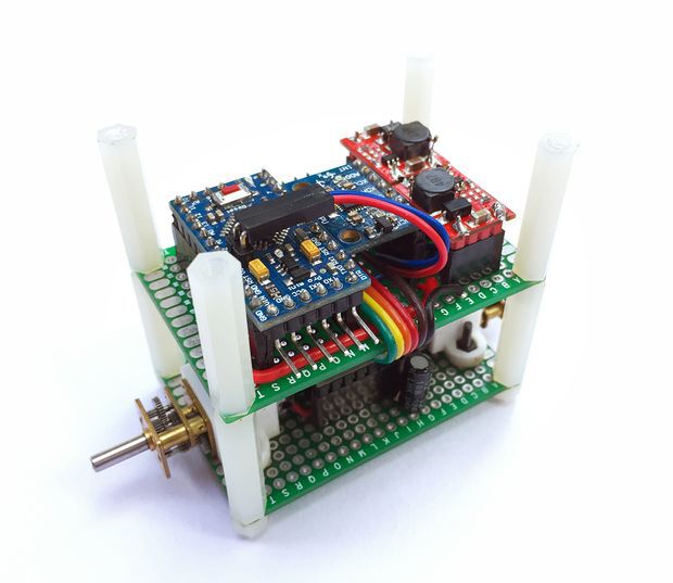
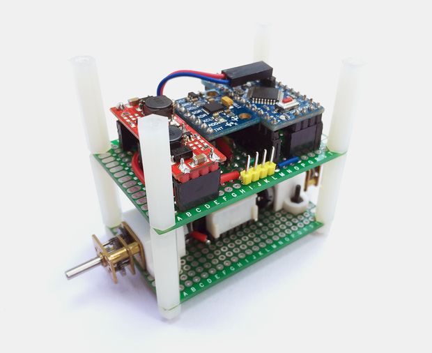
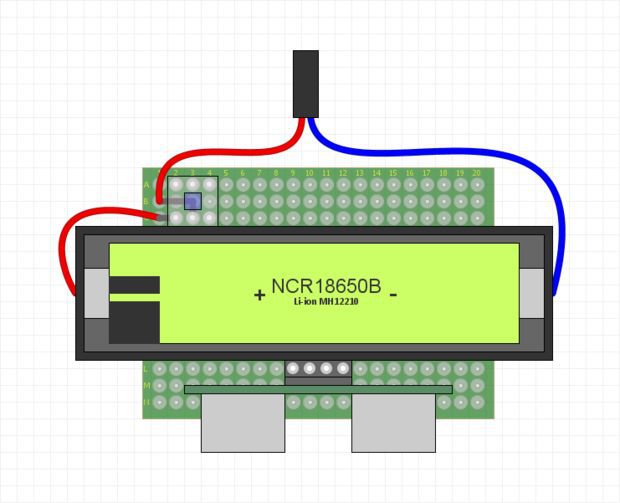
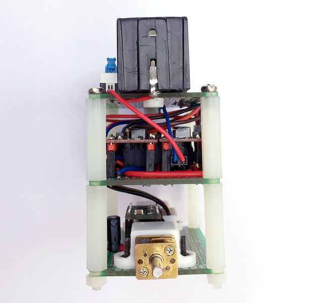
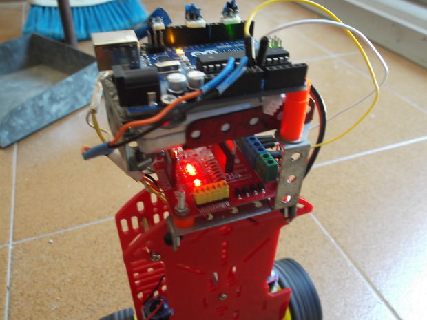
We will first complete the circuitry and structure of the robot. The robot is built on three layers of perfboards that are spaced 25mm apart using nylon spacers. The bottom layer contains the two motors and the motor driver. The middle layer has the controller, the IMU, and the 5V boost regulator modules. The top most layer has the battery, an on/off switch and the ultrasonic distance sensor (we will install this towards the end once we get the robot to balance).
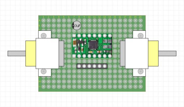
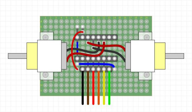
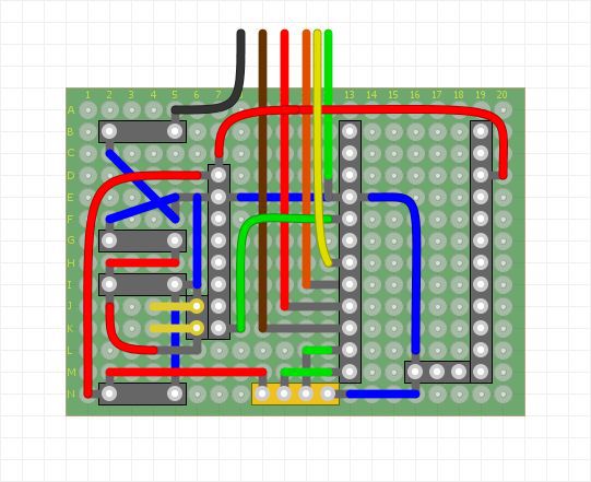
Before we begin to prototype on a perfboard we should have a clear picture about where each part should be placed. To make prototyping easy, it is always better to draw the physical layout of all the components and use this as a reference to place the components and route the jumpers on the perfboard. Once all the parts are placed and soldered, interconnect the three boards using nylon spacers.
You might have noticed that I’ve used two separate voltage regulator modules for driving the motors and the controller even though they both require a 5V source. This is very important. In my first design, I used a single 5V boost regulator to power up the controller as well as the motors. When I switched on the robot, the program freezes intermittently. This was due to the noise generated from the motor circuit acting upon the controller and the IMU. This was effectively eliminated by separating the voltage regulator to the controller and the motor and adding a 10uF capacitor at the motor power supply terminals.
Step 3: Measuring Angle of Inclination Using Accelerometer
The MPU6050 has a 3-axis accelerometer and a 3-axis gyroscope. The accelerometer measures acceleration along the three axes and the gyroscope measures angular rate about the three axes. To measure the angle of inclination of the robot we need acceleration values along y and z-axes. The atan2(y,z)function gives the angle in radians between the positive z-axis of a plane and the point given by the coordinates (z,y) on that plane, with positive sign for counter-clockwise angles (right half-plane, y > 0), and negative sign for clockwise angles (left half-plane, y < 0). We use this library written by Jeff Rowberg to read the data from MPU6050. Upload the code given below and see how the angle of inclination varies.
Try moving the robot forward and backward while keeping it tilted at some fixed angle. You will observe that the angle shown in your serial monitor suddenly changes. This is due to the horizontal component of acceleration interfering with the acceleration values of y and z-axes.
Step 4: Measuring Angle of Inclination Using Gyroscope
The 3-axis gyroscope of MPU6050 measures angular rate (rotational velocity) along the three axes. For our self-balancing robot, the angular velocity along the x-axis alone is sufficient to measure the rate of fall of the robot.
In the code given below, we read the gyro value about the x-axis, convert it to degrees per second and then multiply it with the loop time to obtain the change in angle. We add this to the previous angle to obtain the current angle.
The position of the MPU6050 when the program starts running is the zero inclination point. The angle of inclination will be measured with respect to this point.
Keep the robot steady at a fixed angle and you will observe that the angle will gradually increase or decrease. It won’t stay steady. This is due to the drift which is inherent to the gyroscope.
In the code given above, loop time is calculated using the millis() function which is built into the Arduino IDE. In later steps, we will be using timer interrupts to create precise sampling intervals. This sampling period will also be used in generating the output using a PID controller.
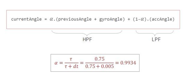
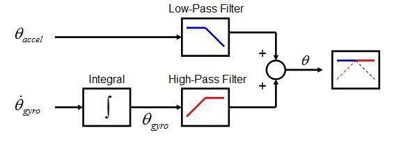
Step 5: Combining the Results With a Complementary Filter
Google defines complementary as “combining in such a way as to enhance or emphasize the qualities of each other or another”.
We have two measurements of the angle from two different sources. The measurement from accelerometer gets affected by sudden horizontal movements and the measurement from gyroscope gradually drifts away from actual value. In other words, the accelerometer reading gets affected by short duration signals and the gyroscope reading by long duration signals. These readings are, in a way, complementary to each other. Combine them both using a Complementary Filter and we get a stable, accurate measurement of the angle. The complementary filter is essentially a high pass filter acting on the gyroscope and a low pass filter acting on the accelerometer to filter out the drift and noise from the measurement.
0.9934 and 0.0066 are filter coefficients for a filter time constant of 0.75s. The low pass filter allows any signal longer than this duration to pass through it and the high pass filter allows any signal shorter than this duration to pass through. The response of the filter can be tweaked by picking the correct time constant. Lowering the time constant will allow more horizontal acceleration to pass through.
Eliminating accelerometer and gyroscope offset errors
Download and run the code given in this page to calibrate the MPU6050’s offsets. Any error due to offset can be eliminated by defining the offset values in the setup() routine as shown below.
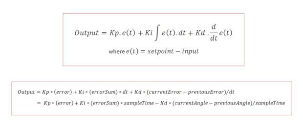
PID stands for Proportional, Integral, and Derivative. Each of these terms provides a unique response to our self-balancing robot.
The proportional term, as its name suggests, generates a response that is proportional to the error. For our system, the error is the angle of inclination of the robot.
The integral term generates a response based on the accumulated error. This is essentially the sum of all the errors multiplied by the sampling period. This is a response based on the behavior of the system in past.
The derivative term is proportional to the derivative of the error. This is the difference between the current error and the previous error divided by the sampling period. This acts as a predictive term that responds to how the robot might behave in the next sampling loop.
Multiplying each of these terms by their corresponding constants (i.e, Kp, Ki and Kd) and summing the result, we generate the output which is then sent as command to drive the motor.
Step 7: Tuning the PID Constants
1. Set Ki and Kd to zero and gradually increase Kp so that the robot starts to oscillate about the zero position.
2. Increase Ki so that the response of the robot is faster when it is out of balance. Ki should be large enough so that the angle of inclination does not increase. The robot should come back to zero position if it is inclined.
3. Increase Kd so as to reduce the oscillations. The overshoots should also be reduced by now.
4. Repeat the above steps by fine tuning each parameter to achieve the best result.
Step 8: Adding the Distance Sensor
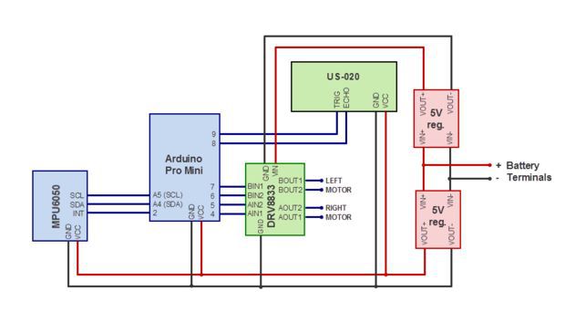
The ultrasonic distance sensor that I’ve used is the US-020. It has four pins namely Vcc, Trig, Echo, and Gnd. It is powered by a 5V source. The trigger and echo pins are respectively connected to digital pins 9 and 8 of Arduino. We will be using the NewPing library to get the distance value from the sensor. We will read the distance once every 100 milliseconds and if the value is between 0 and 20cm, we will command the robot to perform a rotation. This should be sufficient to steer the robot away from the obstacle.
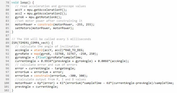
void init_PID() { // initialize Timer1 cli(); // disable global interrupts TCCR1A = 0; // set entire TCCR1A register to 0 TCCR1B = 0; // same for TCCR1B // set compare match register to set sample time 5ms OCR1A = 9999; // turn on CTC mode TCCR1B |= (1 << WGM12); // Set CS11 bit for prescaling by 8 TCCR1B |= (1 << CS11); // enable timer compare interrupt TIMSK1 |= (1 << OCIE1A); sei(); // enable global interrupts }
void setup() { // set the motor control and PWM pins to output mode pinMode(leftMotorPWMPin, OUTPUT); pinMode(leftMotorDirPin, OUTPUT); pinMode(rightMotorPWMPin, OUTPUT); pinMode(rightMotorDirPin, OUTPUT); // set the status LED to output mode pinMode(13, OUTPUT); // initialize the MPU6050 and set offset values mpu.initialize(); mpu.setYAccelOffset(1593); mpu.setZAccelOffset(963); mpu.setXGyroOffset(40); // initialize PID sampling loop init_PID(); }
void loop() { // read acceleration and gyroscope values accY = mpu.getAccelerationY(); accZ = mpu.getAccelerationZ(); gyroX = mpu.getRotationX(); // set motor power after constraining it motorPower = constrain(motorPower, -255, 255); setMotors(motorPower, motorPower); // measure distance every 100 milliseconds if((count%20) == 0){ distanceCm = sonar.ping_cm(); } if((distanceCm < 20) && (distanceCm != 0)) { setMotors(-motorPower, motorPower); } } // The ISR will be called every 5 milliseconds ISR(TIMER1_COMPA_vect) { // calculate the angle of inclination accAngle = atan2(accY, accZ)*RAD_TO_DEG; gyroRate = map(gyroX, -32768, 32767, -250, 250); gyroAngle = (float)gyroRate*sampleTime; currentAngle = 0.9934*(prevAngle + gyroAngle) + 0.0066*(accAngle); error = currentAngle – targetAngle; errorSum = errorSum + error; errorSum = constrain(errorSum, -300, 300); //calculate output from P, I and D values motorPower = Kp*(error) + Ki*(errorSum)*sampleTime – Kd*(currentAngle-prevAngle)/sampleTime; prevAngle = currentAngle; // toggle the led on pin13 every second count++; if(count == 200) { count = 0; digitalWrite(13, !digitalRead(13)); } }
Step 10: Final Thoughts
Spending a bit more time on tweaking the PID constants would give us a better result. The size of our robot also limits the level of stability we can achieve. It is easier to build a full-sized balancing robot than it is to build a small one like ours. Still, I guess, our robot does a pretty decent job in balancing on various surfaces as shown in the video.
That’s it for now.
Thanks for your time. Don’t forget to leave your thoughts in the comments section.
First of all I want to apologize for my English, if you don’t understand something, please, ask.
I know that a self-balancing robot is not new, but when i started this project i found a lot of information, but never in the same site, i had to search a lot to join all information in a single project. Becouse of that i’m making this instrucctable, to show you all the information i get, with all detail, to make that robot.
This project is for all of you that like’s to make robots but don’t have many things, and by things i mean time, money and robotics knowledge. In this project i’m gonna show you the easiest way to do a simple, cheap and useless two wheels self-balancing robot.
I explain the materials and electronics used in the project, how and where to buy or create it and i’m gonna tell you my experience and tips along the way to create this project.
Step 1: Materials
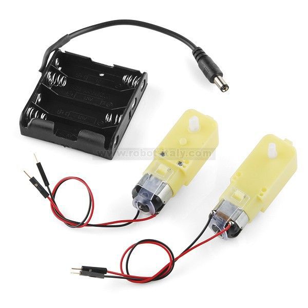
The materials i used for this projects were the cheapest i could get, but there are even cheaper. Principally i buy from two places: DX, a Chinese online store with lots of very cheap electronic (arduino, drivers, sensors,…) and free shipping (that’s a good point); and Robot-Italy, an Italian store specialized in kits for robotics.
From Robot-Italy i get the chassis from a kit for a 3 wheeled robot and the battery, a LiPo of 1300mAh
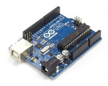
You can buy the Arduino form both stores, in Robot-Italy have the official version (23€) and in DX have the Chinese version (10€), in not gonna open a debate but i used both and they just work fine:
I used materials as cheap if i could but you can use whatever you have, i saw people using servo motors and stepper motors with a good result. This motor driver maybe is much bigger than the needed one, with an L293 it can work, you can make your own chassis and use other type of sensors.
Step 2: Phisics
The physics for this robot are simple, the robot stand in two points lined, the wheel, and i tends to fall and lose his verticality, the movement of the wheel in the direction of the falling rises the robot for recover the vertical position.
A Segway-type vehicle is a classic inverted pendulum control problem that is solvable in two degrees of freedom for the simplest models. The vehicle attempts to correct for an induced lean angle by moving forward or backwards, and the goal is to return itself to vertical. Or at least not fall over.
For that objective we have two things to do, in one hand we have to measure the angle of inclination (Roll) that have the vehicle, and in the other hand we have to control the motors for going forward or backwards to make that angle 0, maintaining his verticality.
Angle Measurement:
For measure the angle we have two sensors, accelerometer and gyroscope, both have his advantages and disadvantages. The accelerometer can measure the force of the gravity, and with that information we can obtain the angle of the robot, the problem of the accelerometer is that it can also measure the rest of the forces the vehicle is someted, so it has lot of error and noise. The gyroscope measure the angular velocity, so if we integrate this measure we can obtain the angle the robot is moved, the problem of this measure is that is not perfect and the integration has a deviation, that means that in short time the measure is so good, but for long time terms the angle will deviate much form the real angle.
Those problems can be resolved be the combination of both sensors, that’s called sensor fusion, and there are a lot of methods to combine it. In this project i try two of them: Kalman Filter, and complementary filter.
The Kalman filter is an algorithm very extended in robotics, and offers a good result with low computational cost. There is a library for arduino that implements this method, but if you want to learn more about that method or implement it by yourself look at this page.
The Complementary filter is a combination of two or more filters that combines the information from different sources and gets the best value you want. It can be implement in only one line of code .For more information visit this page.
angle = A * (angle + gyro * dt) + (1 – A) * accel;
where A is normally equals to 0.98.
First i tried to use Kalman filter but i don’t obtain good results, my angle was calculated with a little delay and it affect the control. The Kalman filter has three variables you can change based on the parameter of your sensor, and varying this you can obtain better result, i tried to change that values, but i don’t get better results so i decided to implement the complementary filter, so much easier and it have less computational cost. The complementary filter works fine for me.
Step 3: Chasis
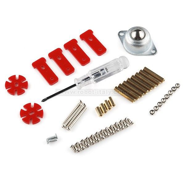
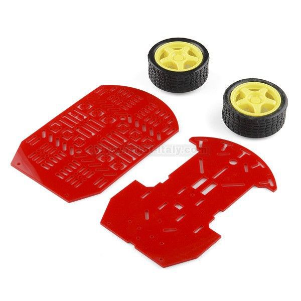
For create the main structure of the robot i used the kit previously mentioned, this kit contains a simple plastic chassis with some nuts and screws, two wheels with two motors, one battery socket, one caster wheel, and even 2 little wheels for encoders. The last time i checked the price was 19€.
Tip: If you like to make your own chassis with wood, aluminium, or other materials and if you have old DC motors and wheels you can save some money.
This kit is prepared to make a 3 wheel vehicle but we gonna change the plans a little to adapt it to our project.
From the kit there are part i don’t use, like the caster wheel, two motor fastenings and some nuts and screws. I put the two motor in the lower part of the structure and closed it with the two grat plastic parts, keeping it together with the screws.
The electronics and the battery creates a tower in the upper part of the structure, i used Meccano to build the tower where the PCBs and the battery were located, but you can use other materials, like plastic, wood metal, or even only tape surrounding everywhere, like a gigant ball of tape.
And Voila! chassis done, not so difficult for the moment, let’s see next step.
Tip: When you build your robot you have to try to put the mass center the higher you can, putting heavy things in the upper part of the robot, like batteries. Remember that the more height of the center of mass the more stability the robot will have.
Step 4: Electronics
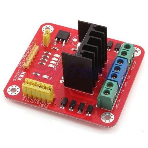
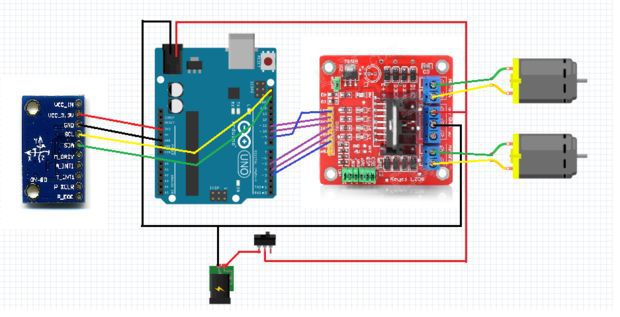
The electronics we are going to use in the project are simply three, an arduino UNO (you can use whatever arduino you have, doesn’t matter if isn’t arduino UNO), a motor driver, in this case a L298, and finally an IMU.
We use a commercial motor driver based on the chip L298, maybe much powerful that we need for these motors but i have it and it works fine. If you want to make you own DC motor driver you can use some transistors and make a H-bridge or use a L293, cheap and easy to use, there is an instructable where you can find information how to do it.
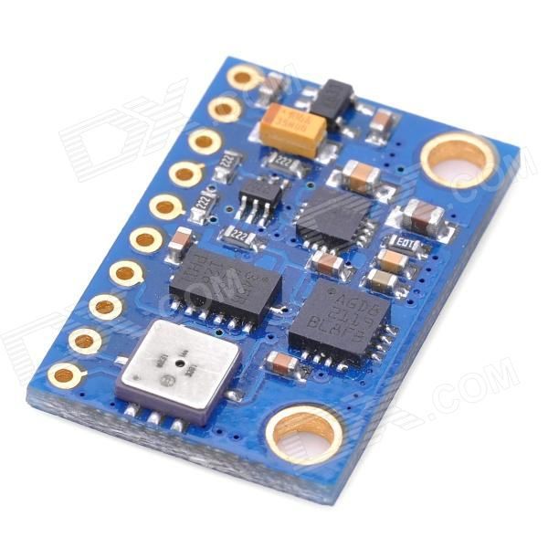
For the IMU i used the cheapest 10DOF (10 Degrees Of Freedom) i find, the chinese GY-80 with 3-axis accelerometer, 3-axis gyroscope, magnetometer, barometer and temperature sensors. We use only accelerometer and gyro so you can save money buying another IMU, like the MPU-6050, a 6DOF IMU for only 3.63€!!!!, or accelerometer and gyro for separate.
The IMU is connected to the arduino using I2C bus (If you want to lerarn more about I2C look this instructable), so we need 2 wires for communication (SDA and SCL) and 2 wires for power, it use 3.3V so we need 3.3V wire and GND.
The motor driver take power directly form the battery so don’t have to connect arduino’s power to it (i mean the 5V form the arduino), but we need 6 wires to control it, 3 for each motor, one for send the PWM signal for control the motor velocity, and for indicate the direction we want the motor to spin.
Tip: Try to position the IMU sensor (or accelerometer) in the line of the axis of the motors because if you locate the IMU far form this you can obtain much error in the accelerometer measure, remember that it measure linear acceleration, if you locate it to a distance R from the axis when the robot falls form vertical the acceleration of the accelerometer is the gravity plus R*dAngle/dt that means that it introduce an error in the measurement.
Step 5: Code
I’m not going to explain every single line of code for the project (i commented the code, if you download it i think u will have no problems to understand it), but i’m gonna show you how i organize it.
The code has 4 files: one the main code, a second one for the motors, the third is for the PID, and the last one is for the sensor code.
In the main code first i initialize the entire robot: pins, sensors, communications, … Then i calculate the error of the sensors. This part it’s very important because in this part we take the initial angle and we make it zero, it means that the sensor have an initial deviation, when we place the robot vertically the sensor don’t show that the angle is zero, instead send a deviation angle, this initial angle is used to subtract it from the posterior measurements of the sensors, to obtain the real angle. So when we initiate the robot we have to maintain it vertically until it starts to move the wheels.
The next part of code is the loop where we take the sensor values every 10 millisecond, that mean the frequency of sampling is 100Hz (you can use whatever frequency , but remember that very low and very high frequencies could not work), and we calculate the angle of the robot using, in this case, the complementary filter previously explained. We have the angle, now we can use that information to control our motors, this uses an intermediate PID, the simplest way to control things efficiently, there is an arduino library for the PID but is simple to implement it, you can code it in no more than 10-20 lines of code.
In order to use the accelerometer, in this case the ADXL345, we have to use its libraries. I used the next adafruit libraries: Adafruit_ADXL345 library and Adafruit_Sensor library.
And that’s all, simple code for simple robot, but it woks fine for me. You can implement so many more things if you want, like LCD screen, more sensors, better control, … That the magic of robots, you make one and improve it as much as you want.
Some of you have troubles using the code, i uploaded a single file with the entire project (Balacing_single_file).
I made a lot of test in the long way for this project, first i prove the motors: direction, velocity, … Then the sensors and the sensor fusion, that was a lot of time for find the right way to use it, i made a simple processing program (included in the code file) to show the values of the sensors graphically:
That help me to understand and to get the right form to take the real angle using Kalman or complementary filter.
At the end i prove the robot itself, the first prove was no as expected but it seems like we can achieve it
After some PID adjust and some code cleaning i reach the goal, maintain the robot vertically all the time, and even recover from pushing it with a little force. As you can see the robot walks with no control, drifting around without sense, but always vertical, that’s we wanted (for now).
Step 7: Improvements
There are some much improvements to do with this robot, this is the first step of many more:
The first i want to implement is the position recovery, i don’t want my robot to walk around the room like a zombie although my cat like it, not me :D. For that we need encoders for measure the movement of the wheel and use it for bring the robot back to the initial position.
Control the movement of the robot, forward, backward and turning , that is easy, the only thing we have to do is change the angle we want the robots stay then the gravity will do his work and the robot will move in the direction of the angle, then we put the angle to zero again and the robot stops. For turning we have to put some offset in the motor velocity, for turning right we subtract the offset to the velocity in right wheel and sum it to the velocity of the left wheel.
Adding a WiFi shield to control it via internet.
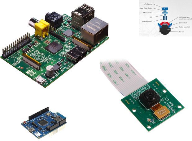
Implementation with Raspberry Pi to allow the robot to use a camera.
Implementation of a camera and artificial vision for the robot.
Use a ball instead of wheels, so hard, but we’ll try.

 Personalize and sign certificates
 Formal invitations
 Work with small and irregularly shaped paper
 Party invitation with fine-point markers
 Printing text with a fountain pen
 with pen") Stipple drawing with pen
Stipple drawing with pen Precision drawing with rollerball pens
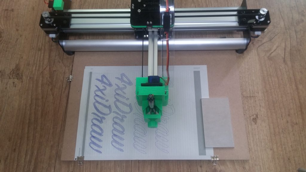 Large writing with permanent marker


 with pen")


 Printable area: US Letter + A4
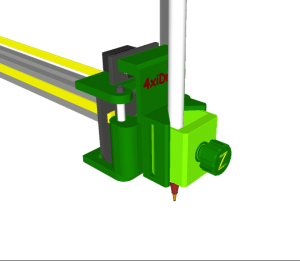 Pen holder: Vertical configuration
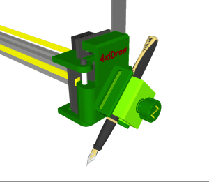 Pen holder: 45-degree configuration
 Pick the right angle for each writing implement