
Tag: Gyro
nRF24 RC Transmitter – Concept
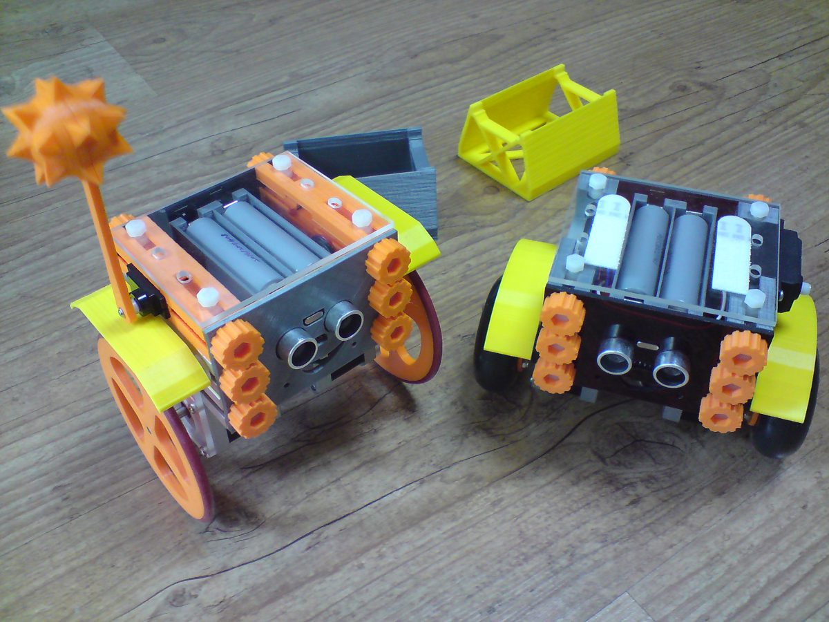
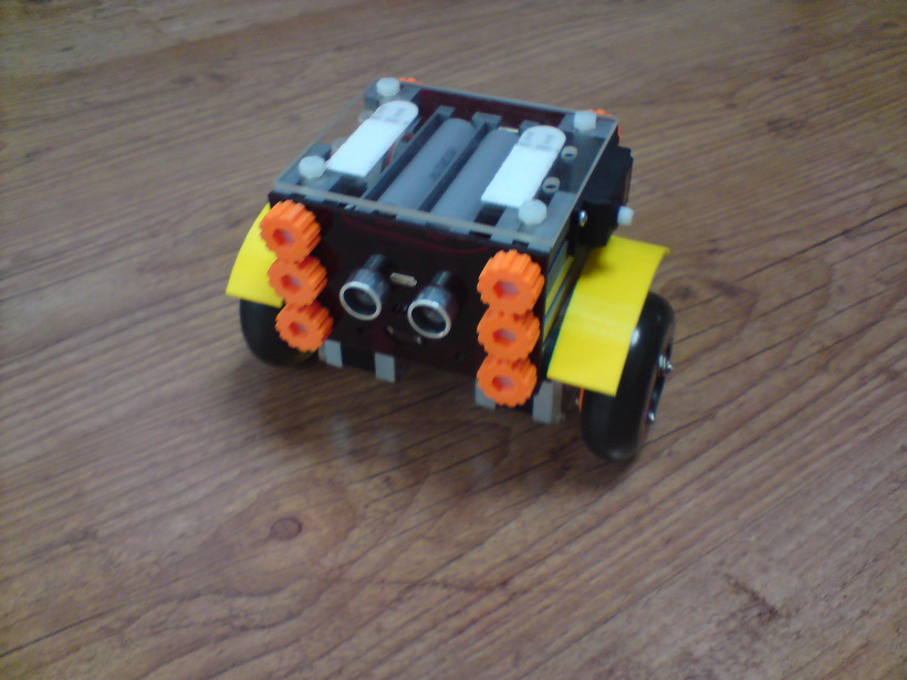
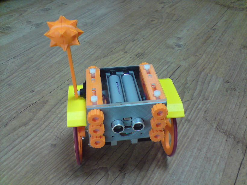
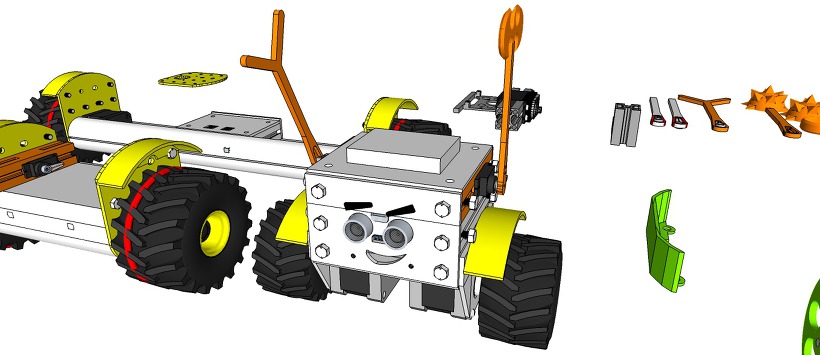
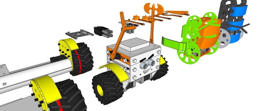
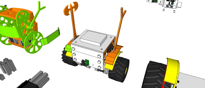
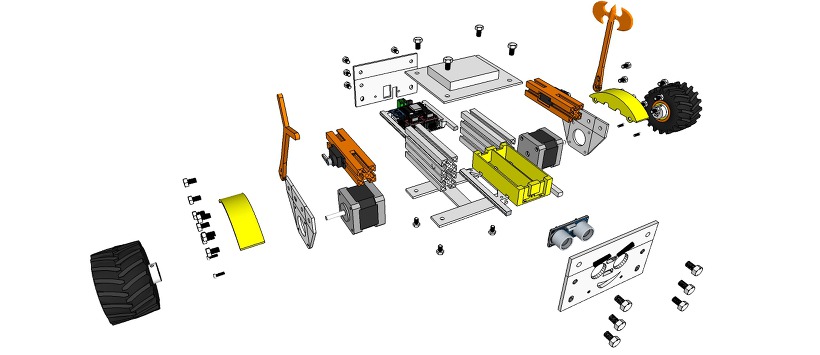
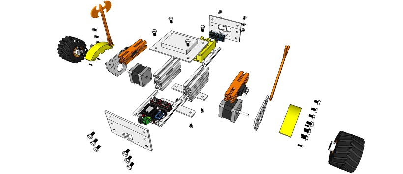
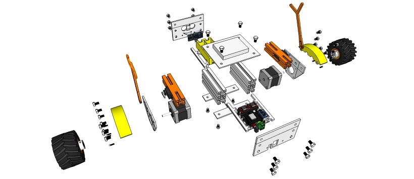
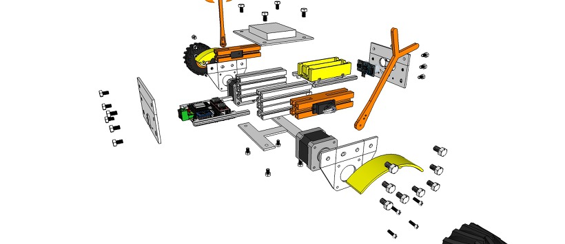
eX-Robot – ProfileBlock™ Robot Platform

[ Upload 20170424]
[ Upload design concept 20170418]
http://www.thingiverse.com/thing:2256715
ProfileBlock – Balancing Robot – DIY Robots Platform
3D Design Tool: SketchUp Pro
ProfileBlock’s robots are built on top of an open source Arduino-based(with ESP8266, Raspberry Pi) platform.
Self Balancing Robot (eX-Robot, B-Robot, Roverbot, …
Hardware_____
Base Plate(Parts):
6 x ProfileBlock™ DF 2020 85mmAcrylic Plate (t = 3mm)1 x Top Plate1 x Bottom Plate
2 x Step Motor Mount Plate
1 x Front Plate
1 x Rear Plate3D Printing Parts
2 x Servo Mount ProfoleBlock
12 x Knob M5 Hexaheard
2 x Wheels 100mm or Inline Wheels 70mm(with 2 x Inline Wheels Hub)
2 x Tire Mudguards
1 x Stand1 x Battery Holder
Step Motor:
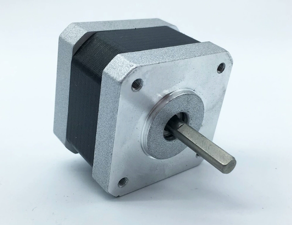
2 x Nema 17 Stepper Motor bipolar 4 leads 34mm 12V 1.3A 26Ncm(36.8oz.in) 3D printer motor 42SHD0001
2 x NEMA 17 – Phase: 4, Step Angle: 1.8 Deg/Step, Holding Torque: 2.6Kg.cm
Servo:
1 x Standard Servo or SG90 Metal Servo
1 x Standard Servo (Option) or SG90 Metal Servo
12 x M5 10mm Nylon Bolts
12 x M5 8mm Nylon Bolts
12 x M5 Nylon Nuts
8 x M3 8mm Bolts
4 x M3 10mm Bolts
4 x M3 15mm Bolts
8 x M3 Nuts
Electrical______
Control Board:
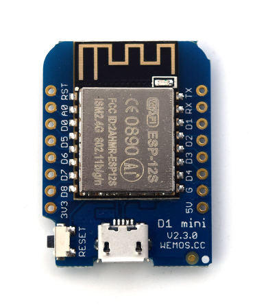
1 x ESP8266 Witty Cloud or WeMos (eX-Robot)
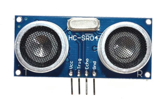
1 x HC-SR04 ultra sonic module
1 X MPU6050
2 x A4988 Step Motor Drive
1 x LM1117-5.0 5,0V 1A Regulator
1 x LM1117-3,3 3,3V 1A Regulator
6 x 100uF 25V Capacitor
4 x 0.1uF Capacitor
1 x 220KOhm Resistor
1 x 100KOhm Resistor
4 x 10KOhm Resistor
7 x 8P Female Pin Header Connector 2.54mm Pitch
3 x 4P Male Pin Header Connector 2.54mm Pitch
2 x 3P Male Pin Header Connector 2.54mm Pitch
3 x 2P Male Pin Header Connector 2.54mm Pitch
1 x 2EDGK 5.08mm 2P Plug-in terminal connectors set
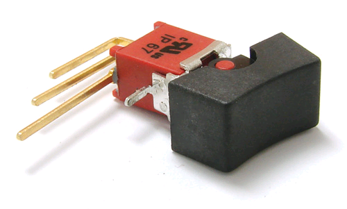
1 x Right Angle SPDT 4 Pin On-On I/O Boat Rocker Switch
1 x Interface Mother boardPower Requirements:8.4VDC
12 VDCBattery:2 x 18650 Litum Ion Battery = 7.2 VDC ~ 8.4 VDCSoftware:
1 x Interface Mother boardPower Requirements:8.4VDC
12 VDCBattery:2 x 18650 Litum Ion Battery = 7.2 VDC ~ 8.4 VDCSoftware:
ESP8266 WeMos D1 mini code: Coming soon…
WiFi UDP Control TouchOSC Layout file: Coming soon…
Arduino IDE (ESP8266 ESP-12E/F)Support SoftAP and StationSupport OTA (at Local network)Support mDNS (at Local network)
The open source ProfileBlock hardware and software is free and made with love. Please show your level of support with a voluntary donation.
Donate:
https://www.paypal.com/cgi-bin/webscr?cmd=_s-xclick&hosted_button_id=RDN7ZGAVFS5UE

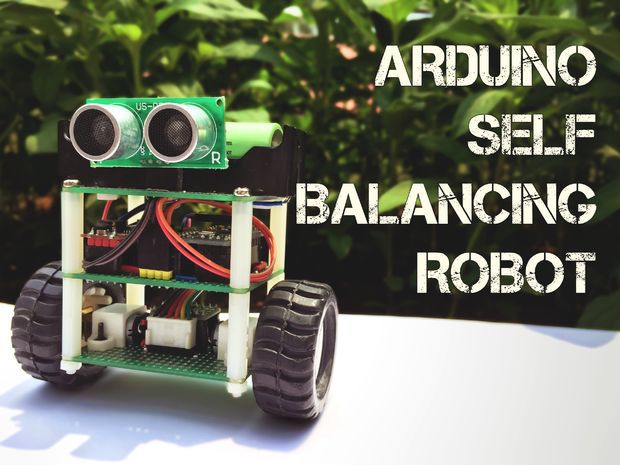
Arduino Self-Balancing Robot

Hello, everyone!
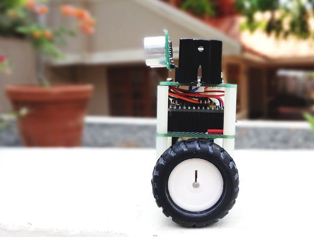
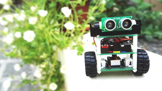
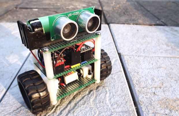
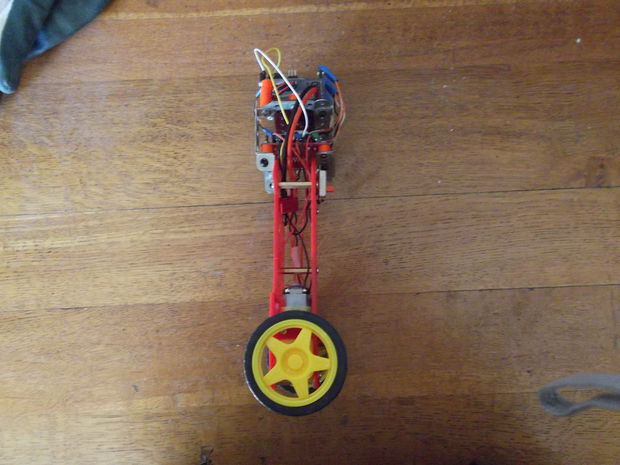
In this instructable, I’ll show you how to build a small self-balancing robot that can move around avoiding obstacles. This is a tiny robot measuring 4 inches wide and 4 inches tall and is based on the Arduino Pro Mini development board and the MPU6050 accelerometer-gyroscope module.
In the steps that follow, we will see how to interface the MPU6050 with Arduino, how to measure the angle of inclination of the robot, how to use PID to make the robot stay balanced. An ultrasonic rangefinder is also added to the robot which prevents it from banging into obstacles as it wanders around.
Parts List
I bought most of these parts from aliexpress but you can find them in any other electronics store as well.
1. Arduino Pro Mini
2. GY-521 module with MPU-6050
3. DRV8833 Pololu motor driver
4. 2, 5V boost converter
5. US-020 ultrasonic distance sensor
6. NCR18650 battery and holder
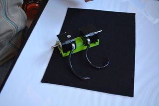
7. Pair of micro metal gear motors (N20, 6V, 200 rpm) and brackets
8. Pair of 42x19mm wheels
9. 3, Double-sided prototype PCB (4cm x 6cm)
10. 8, 25cm Nylon spacers and 4, nylon nuts
Apart from the above, you will need some cables, berg connectors and one on/off switch.
Step 1: A Bit of Theory
Let’s start with some fundamentals before getting our hands dirty.
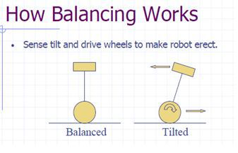
The self-balancing robot is similar to an upside down pendulum. Unlike a normal pendulum which keeps on swinging once given a nudge, this inverted pendulum cannot stay balanced on its own. It will simply fall over. Then how do we balance it? Consider balancing a broomstick on our index finger which is a classic example of balancing an inverted pendulum. We move our finger in the direction in which the stick is falling. Similar is the case with a self-balancing robot, only that the robot will fall either forward or backward. Just like how we balance a stick on our finger, we balance the robot by driving its wheels in the direction in which it is falling. What we are trying to do here is to keep the center of gravity of the robot exactly above the pivot point.
To drive the motors we need some information on the state of the robot. We need to know the direction in which the robot is falling, how much the robot has tilted and the speed with which it is falling. All these information can be deduced from the readings obtained from MPU6050. We combine all these inputs and generate a signal which drives the motors and keeps the robot balanced.
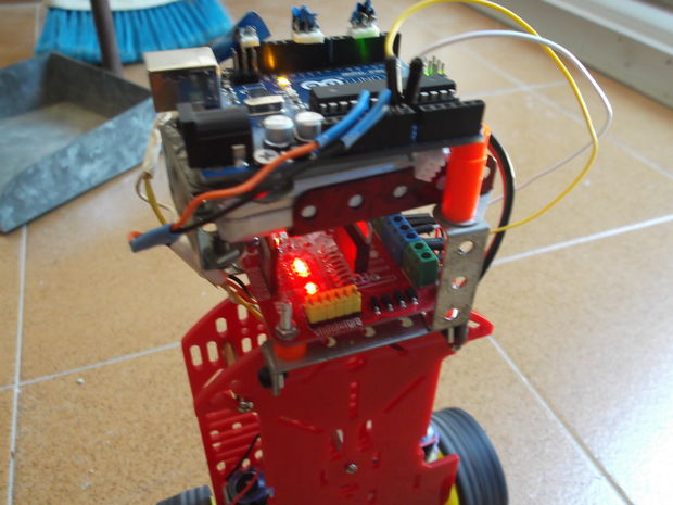
Step 2: Let’s Start Building
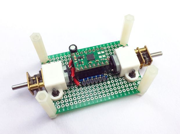
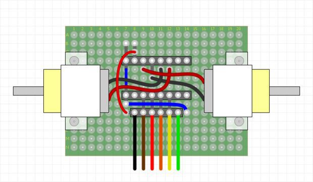
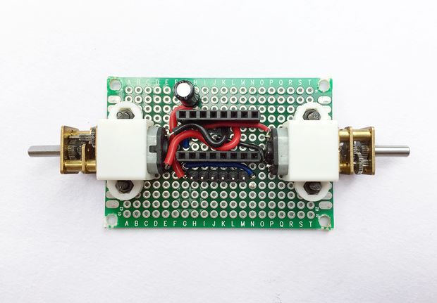
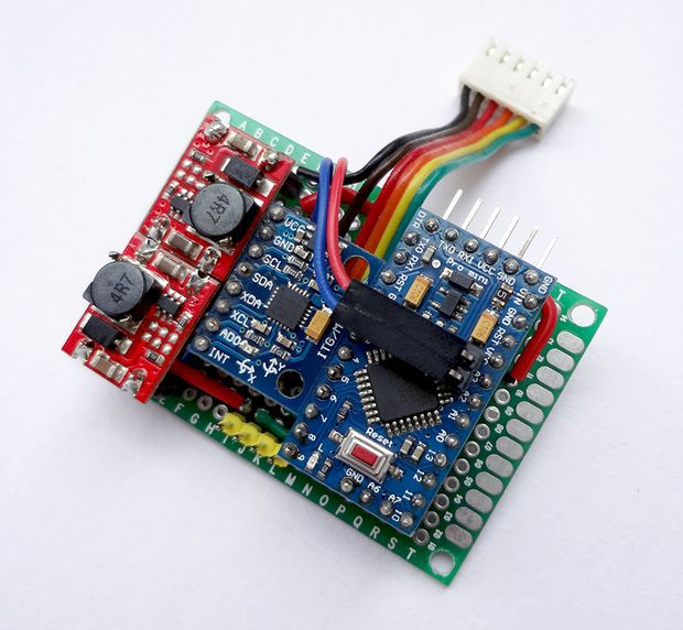
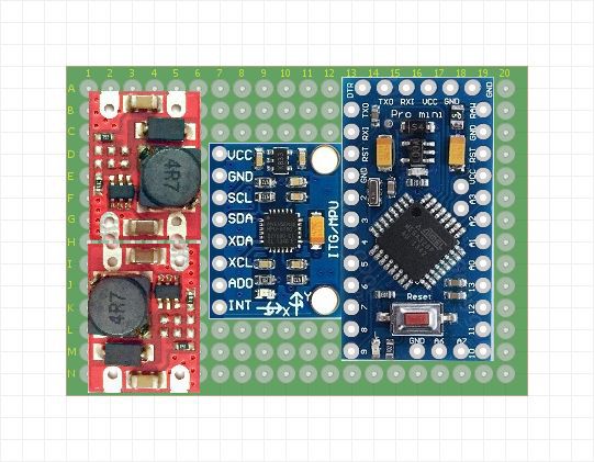
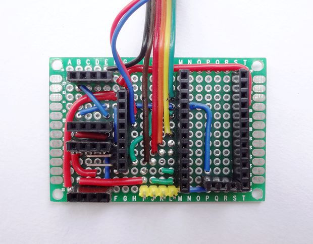
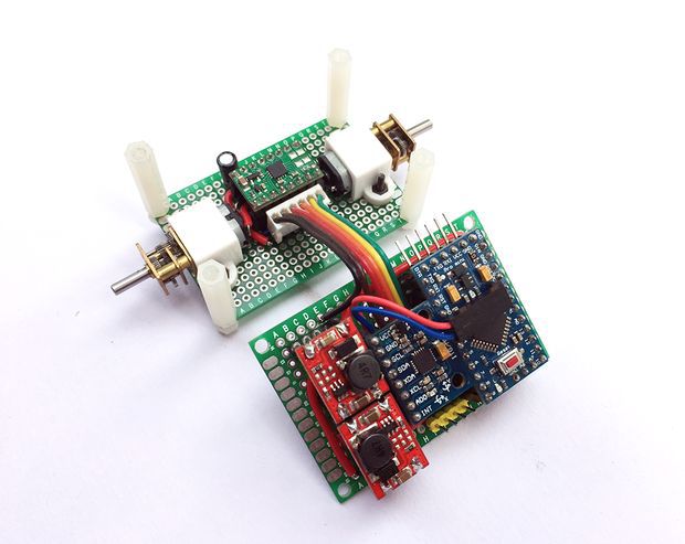
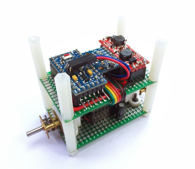
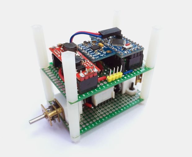
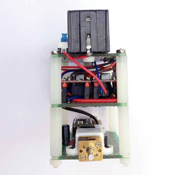
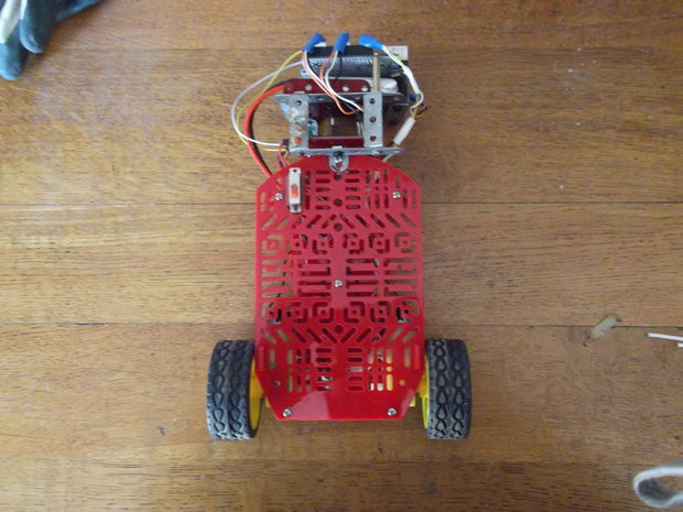
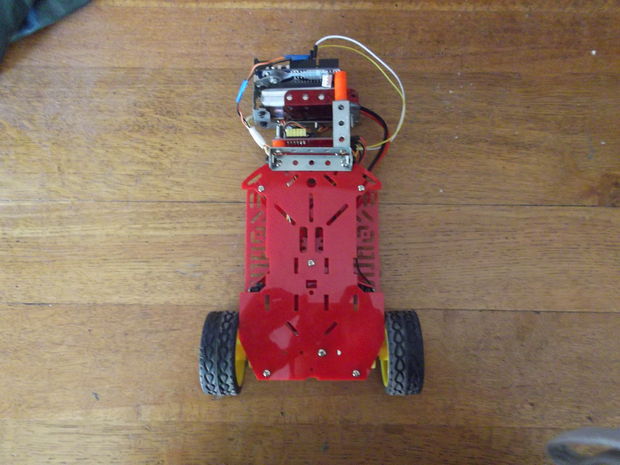
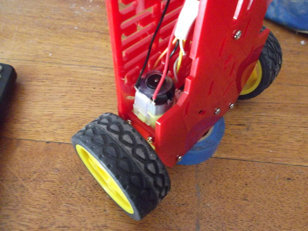
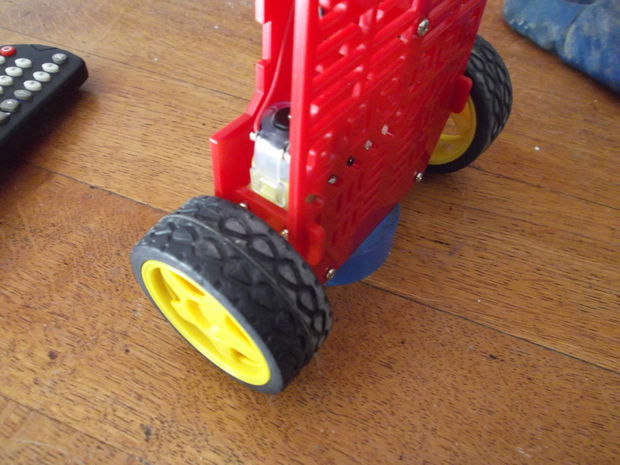
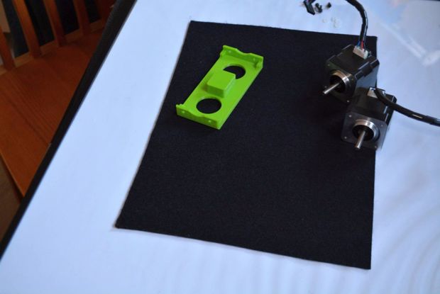
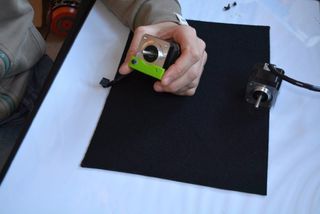
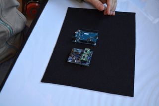
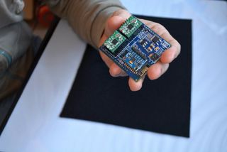
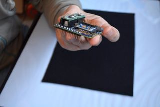
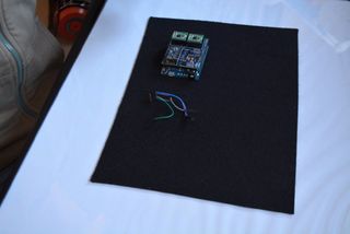
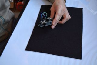
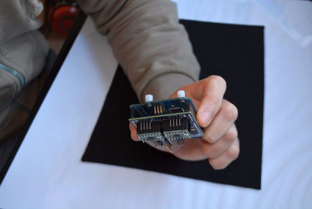
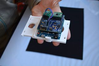
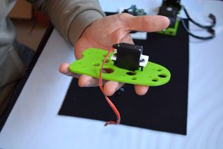
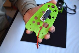
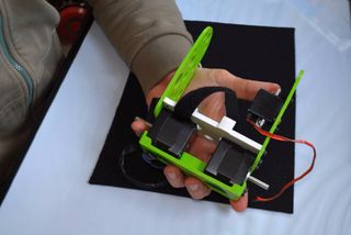
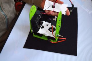
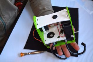
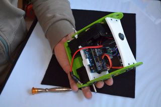
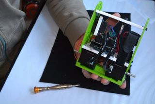
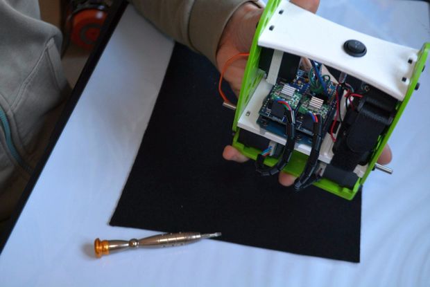
We will first complete the circuitry and structure of the robot. The robot is built on three layers of perfboards that are spaced 25mm apart using nylon spacers. The bottom layer contains the two motors and the motor driver. The middle layer has the controller, the IMU, and the 5V boost regulator modules. The top most layer has the battery, an on/off switch and the ultrasonic distance sensor (we will install this towards the end once we get the robot to balance).
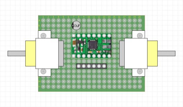
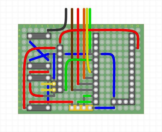
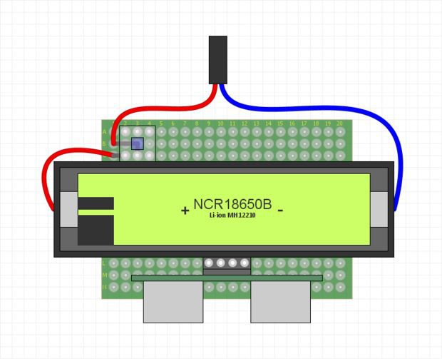
Before we begin to prototype on a perfboard we should have a clear picture about where each part should be placed. To make prototyping easy, it is always better to draw the physical layout of all the components and use this as a reference to place the components and route the jumpers on the perfboard. Once all the parts are placed and soldered, interconnect the three boards using nylon spacers.
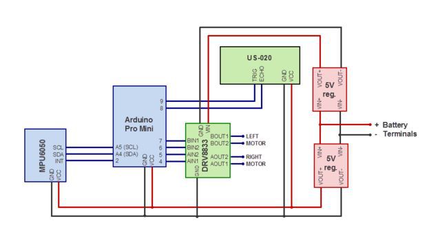
You might have noticed that I’ve used two separate voltage regulator modules for driving the motors and the controller even though they both require a 5V source. This is very important. In my first design, I used a single 5V boost regulator to power up the controller as well as the motors. When I switched on the robot, the program freezes intermittently. This was due to the noise generated from the motor circuit acting upon the controller and the IMU. This was effectively eliminated by separating the voltage regulator to the controller and the motor and adding a 10uF capacitor at the motor power supply terminals.
Step 3: Measuring Angle of Inclination Using Accelerometer

The MPU6050 has a 3-axis accelerometer and a 3-axis gyroscope. The accelerometer measures acceleration along the three axes and the gyroscope measures angular rate about the three axes. To measure the angle of inclination of the robot we need acceleration values along y and z-axes. The atan2(y,z)function gives the angle in radians between the positive z-axis of a plane and the point given by the coordinates (z,y) on that plane, with positive sign for counter-clockwise angles (right half-plane, y > 0), and negative sign for clockwise angles (left half-plane, y < 0). We use this library written by Jeff Rowberg to read the data from MPU6050. Upload the code given below and see how the angle of inclination varies.
#include “Wire.h”
#include “I2Cdev.h” #include “MPU6050.h” #include “math.h”
MPU6050 mpu;
int16_t accY, accZ; float accAngle;
void setup() { mpu.initialize(); Serial.begin(9600); }
void loop() { accZ = mpu.getAccelerationZ(); accY = mpu.getAccelerationY(); accAngle = atan2(accY, accZ)*RAD_TO_DEG; if(isnan(accAngle)); else Serial.println(accAngle); }
Try moving the robot forward and backward while keeping it tilted at some fixed angle. You will observe that the angle shown in your serial monitor suddenly changes. This is due to the horizontal component of acceleration interfering with the acceleration values of y and z-axes.
Step 4: Measuring Angle of Inclination Using Gyroscope
The 3-axis gyroscope of MPU6050 measures angular rate (rotational velocity) along the three axes. For our self-balancing robot, the angular velocity along the x-axis alone is sufficient to measure the rate of fall of the robot.
In the code given below, we read the gyro value about the x-axis, convert it to degrees per second and then multiply it with the loop time to obtain the change in angle. We add this to the previous angle to obtain the current angle.
#include “Wire.h”
#include “I2Cdev.h” #include “MPU6050.h”
MPU6050 mpu;
int16_t gyroX, gyroRate; float gyroAngle=0; unsigned long currTime, prevTime=0, loopTime;
void setup() { mpu.initialize(); Serial.begin(9600); }
void loop() { currTime = millis(); loopTime = currTime – prevTime; prevTime = currTime; gyroX = mpu.getRotationX(); gyroRate = map(gyroX, -32768, 32767, -250, 250); gyroAngle = gyroAngle + (float)gyroRate*loopTime/1000; Serial.println(gyroAngle); }
The position of the MPU6050 when the program starts running is the zero inclination point. The angle of inclination will be measured with respect to this point.
Keep the robot steady at a fixed angle and you will observe that the angle will gradually increase or decrease. It won’t stay steady. This is due to the drift which is inherent to the gyroscope.
In the code given above, loop time is calculated using the millis() function which is built into the Arduino IDE. In later steps, we will be using timer interrupts to create precise sampling intervals. This sampling period will also be used in generating the output using a PID controller.
Step 5: Combining the Results With a Complementary Filter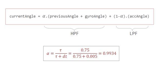
Google defines complementary as “combining in such a way as to enhance or emphasize the qualities of each other or another”.
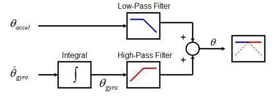
We have two measurements of the angle from two different sources. The measurement from accelerometer gets affected by sudden horizontal movements and the measurement from gyroscope gradually drifts away from actual value. In other words, the accelerometer reading gets affected by short duration signals and the gyroscope reading by long duration signals. These readings are, in a way, complementary to each other. Combine them both using a Complementary Filter and we get a stable, accurate measurement of the angle. The complementary filter is essentially a high pass filter acting on the gyroscope and a low pass filter acting on the accelerometer to filter out the drift and noise from the measurement.
currentAngle = 0.9934 * (previousAngle + gyroAngle) + 0.0066 * (accAngle)
0.9934 and 0.0066 are filter coefficients for a filter time constant of 0.75s. The low pass filter allows any signal longer than this duration to pass through it and the high pass filter allows any signal shorter than this duration to pass through. The response of the filter can be tweaked by picking the correct time constant. Lowering the time constant will allow more horizontal acceleration to pass through.
Eliminating accelerometer and gyroscope offset errors
Download and run the code given in this page to calibrate the MPU6050’s offsets. Any error due to offset can be eliminated by defining the offset values in the setup() routine as shown below.
mpu.setYAccelOffset(1593);
mpu.setZAccelOffset(963); mpu.setXGyroOffset(40);
Step 6: PID Control for Generating Output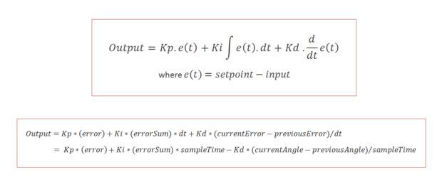
PID stands for Proportional, Integral, and Derivative. Each of these terms provides a unique response to our self-balancing robot.
The proportional term, as its name suggests, generates a response that is proportional to the error. For our system, the error is the angle of inclination of the robot.
The integral term generates a response based on the accumulated error. This is essentially the sum of all the errors multiplied by the sampling period. This is a response based on the behavior of the system in past.
The derivative term is proportional to the derivative of the error. This is the difference between the current error and the previous error divided by the sampling period. This acts as a predictive term that responds to how the robot might behave in the next sampling loop.
Multiplying each of these terms by their corresponding constants (i.e, Kp, Ki and Kd) and summing the result, we generate the output which is then sent as command to drive the motor.
Step 7: Tuning the PID Constants
1. Set Ki and Kd to zero and gradually increase Kp so that the robot starts to oscillate about the zero position.
2. Increase Ki so that the response of the robot is faster when it is out of balance. Ki should be large enough so that the angle of inclination does not increase. The robot should come back to zero position if it is inclined.
3. Increase Kd so as to reduce the oscillations. The overshoots should also be reduced by now.
4. Repeat the above steps by fine tuning each parameter to achieve the best result.
Step 8: Adding the Distance Sensor
The ultrasonic distance sensor that I’ve used is the US-020. It has four pins namely Vcc, Trig, Echo, and Gnd. It is powered by a 5V source. The trigger and echo pins are respectively connected to digital pins 9 and 8 of Arduino. We will be using the NewPing library to get the distance value from the sensor. We will read the distance once every 100 milliseconds and if the value is between 0 and 20cm, we will command the robot to perform a rotation. This should be sufficient to steer the robot away from the obstacle.
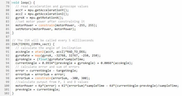
Step 9: The Complete Code
#include "Wire.h"
#include “I2Cdev.h” #include “MPU6050.h” #include “math.h” #include <NewPing.h>
#define leftMotorPWMPin 6 #define leftMotorDirPin 7 #define rightMotorPWMPin 5 #define rightMotorDirPin 4
#define TRIGGER_PIN 9 #define ECHO_PIN 8 #define MAX_DISTANCE 75
#define Kp 40 #define Kd 0.05 #define Ki 40 #define sampleTime 0.005 #define targetAngle -2.5
MPU6050 mpu; NewPing sonar(TRIGGER_PIN, ECHO_PIN, MAX_DISTANCE);
int16_t accY, accZ, gyroX; volatile int motorPower, gyroRate; volatile float accAngle, gyroAngle, currentAngle, prevAngle=0, error, prevError=0, errorSum=0; volatile byte count=0; int distanceCm;
void setMotors(int leftMotorSpeed, int rightMotorSpeed) { if(leftMotorSpeed >= 0) { analogWrite(leftMotorPWMPin, leftMotorSpeed); digitalWrite(leftMotorDirPin, LOW); } else { analogWrite(leftMotorPWMPin, 255 + leftMotorSpeed); digitalWrite(leftMotorDirPin, HIGH); } if(rightMotorSpeed >= 0) { analogWrite(rightMotorPWMPin, rightMotorSpeed); digitalWrite(rightMotorDirPin, LOW); } else { analogWrite(rightMotorPWMPin, 255 + rightMotorSpeed); digitalWrite(rightMotorDirPin, HIGH); } }
void init_PID() { // initialize Timer1 cli(); // disable global interrupts TCCR1A = 0; // set entire TCCR1A register to 0 TCCR1B = 0; // same for TCCR1B // set compare match register to set sample time 5ms OCR1A = 9999; // turn on CTC mode TCCR1B |= (1 << WGM12); // Set CS11 bit for prescaling by 8 TCCR1B |= (1 << CS11); // enable timer compare interrupt TIMSK1 |= (1 << OCIE1A); sei(); // enable global interrupts }
void setup() { // set the motor control and PWM pins to output mode pinMode(leftMotorPWMPin, OUTPUT); pinMode(leftMotorDirPin, OUTPUT); pinMode(rightMotorPWMPin, OUTPUT); pinMode(rightMotorDirPin, OUTPUT); // set the status LED to output mode pinMode(13, OUTPUT); // initialize the MPU6050 and set offset values mpu.initialize(); mpu.setYAccelOffset(1593); mpu.setZAccelOffset(963); mpu.setXGyroOffset(40); // initialize PID sampling loop init_PID(); }
void loop() { // read acceleration and gyroscope values accY = mpu.getAccelerationY(); accZ = mpu.getAccelerationZ(); gyroX = mpu.getRotationX(); // set motor power after constraining it motorPower = constrain(motorPower, -255, 255); setMotors(motorPower, motorPower); // measure distance every 100 milliseconds if((count%20) == 0){ distanceCm = sonar.ping_cm(); } if((distanceCm < 20) && (distanceCm != 0)) { setMotors(-motorPower, motorPower); } } // The ISR will be called every 5 milliseconds ISR(TIMER1_COMPA_vect) { // calculate the angle of inclination accAngle = atan2(accY, accZ)*RAD_TO_DEG; gyroRate = map(gyroX, -32768, 32767, -250, 250); gyroAngle = (float)gyroRate*sampleTime; currentAngle = 0.9934*(prevAngle + gyroAngle) + 0.0066*(accAngle); error = currentAngle – targetAngle; errorSum = errorSum + error; errorSum = constrain(errorSum, -300, 300); //calculate output from P, I and D values motorPower = Kp*(error) + Ki*(errorSum)*sampleTime – Kd*(currentAngle-prevAngle)/sampleTime; prevAngle = currentAngle; // toggle the led on pin13 every second count++; if(count == 200) { count = 0; digitalWrite(13, !digitalRead(13)); } }
Step 10: Final Thoughts
Spending a bit more time on tweaking the PID constants would give us a better result. The size of our robot also limits the level of stability we can achieve. It is easier to build a full-sized balancing robot than it is to build a small one like ours. Still, I guess, our robot does a pretty decent job in balancing on various surfaces as shown in the video.
That’s it for now.
Thanks for your time. Don’t forget to leave your thoughts in the comments section.
Self Balancing Robot

First of all I want to apologize for my English, if you don’t understand something, please, ask.
I know that a self-balancing robot is not new, but when i started this project i found a lot of information, but never in the same site, i had to search a lot to join all information in a single project. Becouse of that i’m making this instrucctable, to show you all the information i get, with all detail, to make that robot.
This project is for all of you that like’s to make robots but don’t have many things, and by things i mean time, money and robotics knowledge. In this project i’m gonna show you the easiest way to do a simple, cheap and useless two wheels self-balancing robot.
I explain the materials and electronics used in the project, how and where to buy or create it and i’m gonna tell you my experience and tips along the way to create this project.
Step 1: Materials
The materials i used for this projects were the cheapest i could get, but there are even cheaper. Principally i buy from two places: DX, a Chinese online store with lots of very cheap electronic (arduino, drivers, sensors,…) and free shipping (that’s a good point); and Robot-Italy, an Italian store specialized in kits for robotics.
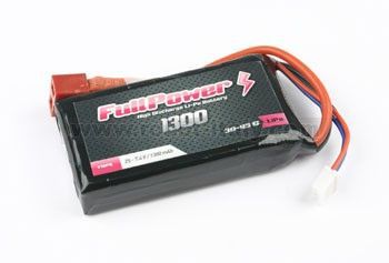
From Robot-Italy i get the chassis from a kit for a 3 wheeled robot and the battery, a LiPo of 1300mAh
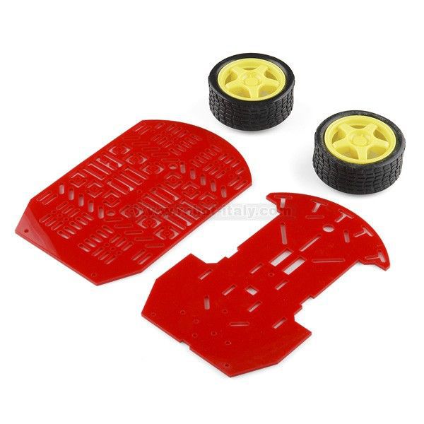
Chassis:
http://www.robot-italy.com/en/magician-chassis-kit…
Batery:
http://www.robot-italy.com/en/fullpower-batteria-l…
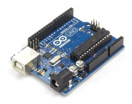
You can buy the Arduino form both stores, in Robot-Italy have the official version (23€) and in DX have the Chinese version (10€), in not gonna open a debate but i used both and they just work fine:
http://www.robot-italy.com/en/arduino-uno-r3.html
http://www.dx.com/p/uno-r3-development-board-micro…
The last two thing left are the IMU sensor and the motor driver, both bought from DX:
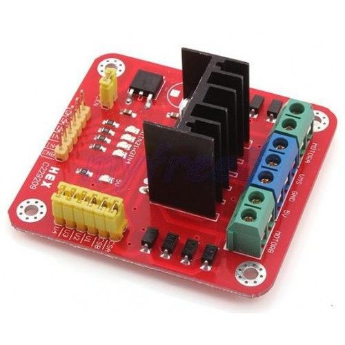
Motor driver:
http://www.dx.com/p/l298n-stepper-motor-driver-con…
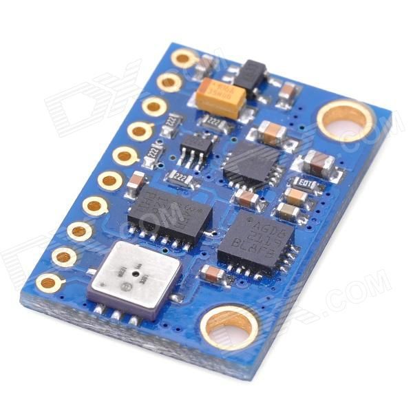
IMU sensor:
http://www.dx.com/p/gy-80-bmp085-9-axis-magnetic-a…
Making a price summary:
Arduino UNO ——————–> 10-20 €
IMU sensor ——————–> 15 €
Motor driver ——————–> 4 €
Chassis ——————–> 19 €
Battery ——————–> 10 €
______________________________________
TOTAL : 58-68 €
I used materials as cheap if i could but you can use whatever you have, i saw people using servo motors and stepper motors with a good result. This motor driver maybe is much bigger than the needed one, with an L293 it can work, you can make your own chassis and use other type of sensors.
Step 2: Phisics
The physics for this robot are simple, the robot stand in two points lined, the wheel, and i tends to fall and lose his verticality, the movement of the wheel in the direction of the falling rises the robot for recover the vertical position.
A Segway-type vehicle is a classic inverted pendulum control problem that is solvable in two degrees of freedom for the simplest models. The vehicle attempts to correct for an induced lean angle by moving forward or backwards, and the goal is to return itself to vertical. Or at least not fall over.
For that objective we have two things to do, in one hand we have to measure the angle of inclination (Roll) that have the vehicle, and in the other hand we have to control the motors for going forward or backwards to make that angle 0, maintaining his verticality.
Angle Measurement:
For measure the angle we have two sensors, accelerometer and gyroscope, both have his advantages and disadvantages. The accelerometer can measure the force of the gravity, and with that information we can obtain the angle of the robot, the problem of the accelerometer is that it can also measure the rest of the forces the vehicle is someted, so it has lot of error and noise. The gyroscope measure the angular velocity, so if we integrate this measure we can obtain the angle the robot is moved, the problem of this measure is that is not perfect and the integration has a deviation, that means that in short time the measure is so good, but for long time terms the angle will deviate much form the real angle.
Those problems can be resolved be the combination of both sensors, that’s called sensor fusion, and there are a lot of methods to combine it. In this project i try two of them: Kalman Filter, and complementary filter.
- The Kalman filter is an algorithm very extended in robotics, and offers a good result with low computational cost. There is a library for arduino that implements this method, but if you want to learn more about that method or implement it by yourself look at this page.
- The Complementary filter is a combination of two or more filters that combines the information from different sources and gets the best value you want. It can be implement in only one line of code .For more information visit this page.
angle = A * (angle + gyro * dt) + (1 – A) * accel;
where A is normally equals to 0.98.
First i tried to use Kalman filter but i don’t obtain good results, my angle was calculated with a little delay and it affect the control. The Kalman filter has three variables you can change based on the parameter of your sensor, and varying this you can obtain better result, i tried to change that values, but i don’t get better results so i decided to implement the complementary filter, so much easier and it have less computational cost. The complementary filter works fine for me.
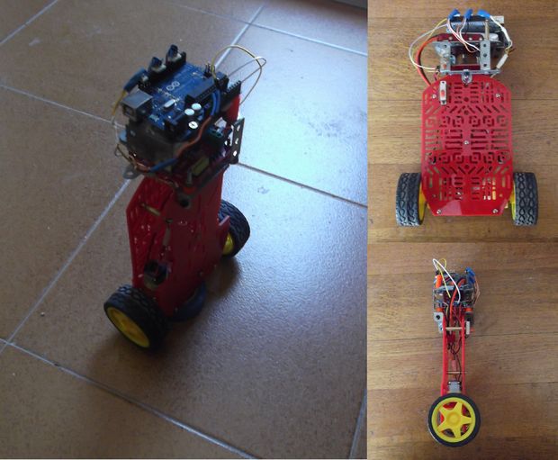
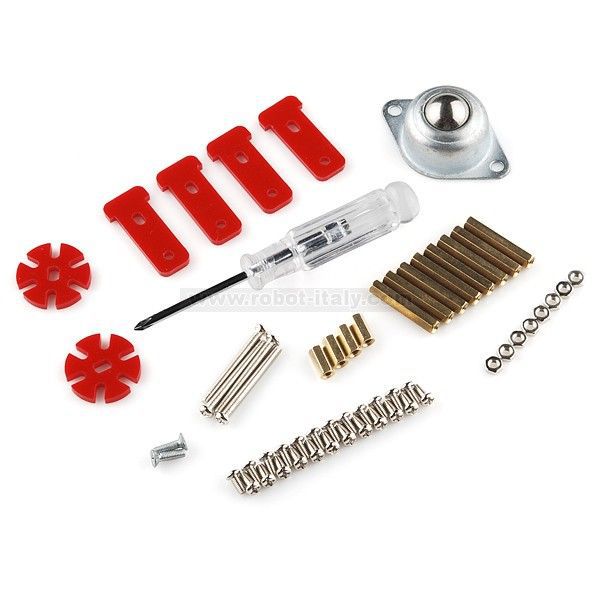
Step 3: Chasis
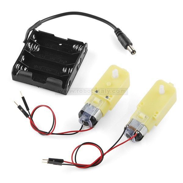
For create the main structure of the robot i used the kit previously mentioned, this kit contains a simple plastic chassis with some nuts and screws, two wheels with two motors, one battery socket, one caster wheel, and even 2 little wheels for encoders. The last time i checked the price was 19€.
Tip: If you like to make your own chassis with wood, aluminium, or other materials and if you have old DC motors and wheels you can save some money.
This kit is prepared to make a 3 wheel vehicle but we gonna change the plans a little to adapt it to our project.
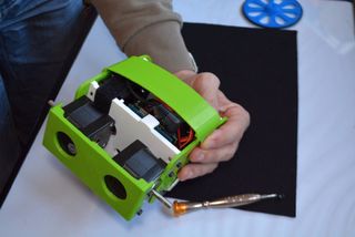
From the kit there are part i don’t use, like the caster wheel, two motor fastenings and some nuts and screws. I put the two motor in the lower part of the structure and closed it with the two grat plastic parts, keeping it together with the screws.
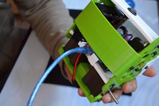
The electronics and the battery creates a tower in the upper part of the structure, i used Meccano to build the tower where the PCBs and the battery were located, but you can use other materials, like plastic, wood metal, or even only tape surrounding everywhere, like a gigant ball of tape.
And Voila! chassis done, not so difficult for the moment, let’s see next step.
Tip: When you build your robot you have to try to put the mass center the higher you can, putting heavy things in the upper part of the robot, like batteries. Remember that the more height of the center of mass the more stability the robot will have.
Step 4: Electronics
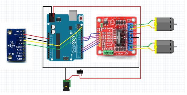
The electronics we are going to use in the project are simply three, an arduino UNO (you can use whatever arduino you have, doesn’t matter if isn’t arduino UNO), a motor driver, in this case a L298, and finally an IMU.
We use a commercial motor driver based on the chip L298, maybe much powerful that we need for these motors but i have it and it works fine. If you want to make you own DC motor driver you can use some transistors and make a H-bridge or use a L293, cheap and easy to use, there is an instructable where you can find information how to do it.
For the IMU i used the cheapest 10DOF (10 Degrees Of Freedom) i find, the chinese GY-80 with 3-axis accelerometer, 3-axis gyroscope, magnetometer, barometer and temperature sensors. We use only accelerometer and gyro so you can save money buying another IMU, like the MPU-6050, a 6DOF IMU for only 3.63€!!!!, or accelerometer and gyro for separate.
The IMU is connected to the arduino using I2C bus (If you want to lerarn more about I2C look this instructable), so we need 2 wires for communication (SDA and SCL) and 2 wires for power, it use 3.3V so we need 3.3V wire and GND.
The motor driver take power directly form the battery so don’t have to connect arduino’s power to it (i mean the 5V form the arduino), but we need 6 wires to control it, 3 for each motor, one for send the PWM signal for control the motor velocity, and for indicate the direction we want the motor to spin.
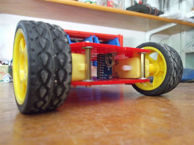
Tip: Try to position the IMU sensor (or accelerometer) in the line of the axis of the motors because if you locate the IMU far form this you can obtain much error in the accelerometer measure, remember that it measure linear acceleration, if you locate it to a distance R from the axis when the robot falls form vertical the acceleration of the accelerometer is the gravity plus R*dAngle/dt that means that it introduce an error in the measurement.
Step 5: Code
I’m not going to explain every single line of code for the project (i commented the code, if you download it i think u will have no problems to understand it), but i’m gonna show you how i organize it.
The code has 4 files: one the main code, a second one for the motors, the third is for the PID, and the last one is for the sensor code.
In the main code first i initialize the entire robot: pins, sensors, communications, … Then i calculate the error of the sensors. This part it’s very important because in this part we take the initial angle and we make it zero, it means that the sensor have an initial deviation, when we place the robot vertically the sensor don’t show that the angle is zero, instead send a deviation angle, this initial angle is used to subtract it from the posterior measurements of the sensors, to obtain the real angle. So when we initiate the robot we have to maintain it vertically until it starts to move the wheels.
The next part of code is the loop where we take the sensor values every 10 millisecond, that mean the frequency of sampling is 100Hz (you can use whatever frequency , but remember that very low and very high frequencies could not work), and we calculate the angle of the robot using, in this case, the complementary filter previously explained. We have the angle, now we can use that information to control our motors, this uses an intermediate PID, the simplest way to control things efficiently, there is an arduino library for the PID but is simple to implement it, you can code it in no more than 10-20 lines of code.
In order to use the accelerometer, in this case the ADXL345, we have to use its libraries. I used the next adafruit libraries: Adafruit_ADXL345 library and Adafruit_Sensor library.
And that’s all, simple code for simple robot, but it woks fine for me. You can implement so many more things if you want, like LCD screen, more sensors, better control, … That the magic of robots, you make one and improve it as much as you want.
Some of you have troubles using the code, i uploaded a single file with the entire project (Balacing_single_file).
Link to the google drive folder:

Step 6: Tests

I made a lot of test in the long way for this project, first i prove the motors: direction, velocity, … Then the sensors and the sensor fusion, that was a lot of time for find the right way to use it, i made a simple processing program (included in the code file) to show the values of the sensors graphically:
That help me to understand and to get the right form to take the real angle using Kalman or complementary filter.
At the end i prove the robot itself, the first prove was no as expected but it seems like we can achieve it
After some PID adjust and some code cleaning i reach the goal, maintain the robot vertically all the time, and even recover from pushing it with a little force. As you can see the robot walks with no control, drifting around without sense, but always vertical, that’s we wanted (for now).
Step 7: Improvements
There are some much improvements to do with this robot, this is the first step of many more:
- The first i want to implement is the position recovery, i don’t want my robot to walk around the room like a zombie although my cat like it, not me :D. For that we need encoders for measure the movement of the wheel and use it for bring the robot back to the initial position.
- Control the movement of the robot, forward, backward and turning , that is easy, the only thing we have to do is change the angle we want the robots stay then the gravity will do his work and the robot will move in the direction of the angle, then we put the angle to zero again and the robot stops. For turning we have to put some offset in the motor velocity, for turning right we subtract the offset to the velocity in right wheel and sum it to the velocity of the left wheel.
- Adding a WiFi shield to control it via internet.
- Implementation with Raspberry Pi to allow the robot to use a camera.
- Implementation of a camera and artificial vision for the robot.
- Use a ball instead of wheels, so hard, but we’ll try.
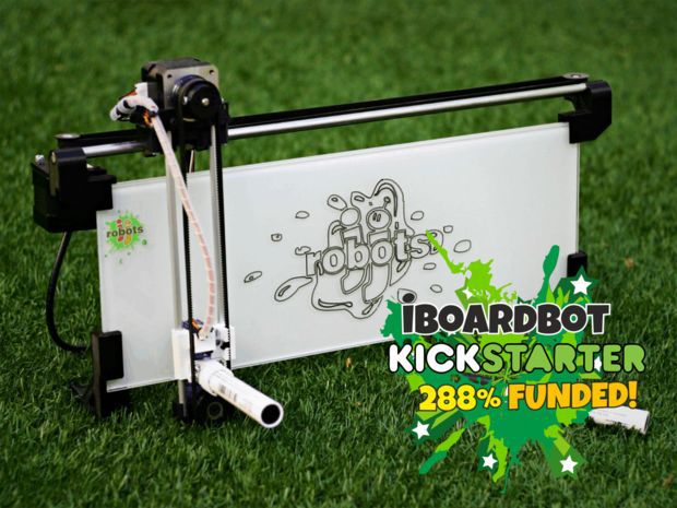
Creating a Remotely Controlled Arduino Self Balancing Robot: B-robot EVO


How does it work?
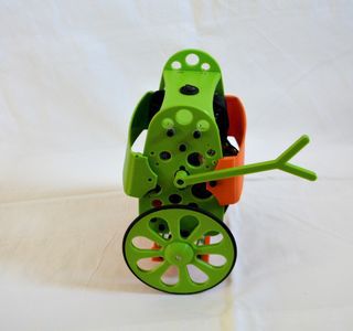
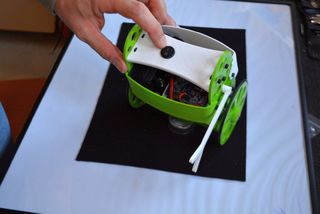
B-ROBOT EVO is a remotely controlled self balancing arduino robot created with 3D printed parts. With only two wheels, B-ROBOT is able to maintain its balance all the time by using his internal sensors and driving the motors. You can control your Robot, making him move or spin, by sending commands via a Smartphone, Tablet or PC while it maintains its balance.
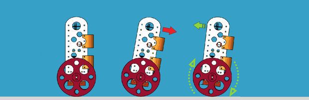
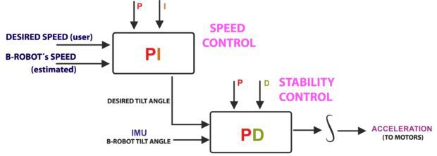
This self balancing robot reads his inertial sensors (accelerometers and gyroscopes integrated on the MPU6000 chip) 200 times per second. He calculates his attitude (angle with respect to the horizon) and compares this angle with the target angle (0º if he wants to maintain balance without moving, or a positive or negative angle if he wants to move forward or backwards). Using the difference between the target angle (let’s say 0º) and actual angle (let’s say 3º) he drives a Control System to send the right commands to the motors to maintain his balance. The commands to the motors are accelerations. For example if the robot is tilted forward (angle of robot is 3º) then he sends a command to the motors to accelerate forward until this angle is reduced to zero to preserve the balance.
Step 1: A Bit More in Depth…
The physical problem that B-ROBOT solves is called the Inverted Pendulum. This is the same mechanism you need to balance an umbrella above your hand. The pivot point is under the center of mass of the object. More information on Inverted Pendulum here. The mathematical solution to the problem is not easy but we don’t need to understand it in order to solve our robot´s balance issue. What we need to know is how should do to restore the robot´s balance so we can implement a Control Algorithm to resolve the problem.
A Control System is very useful in Robotics (an Industrial automation). Basically it´s a code that receives information from sensors and target commands as inputs and creates, in consequence, output signals to drive the Robot actuators (the motors in our example) in order to regulate the system. We are using a PID controller (Proportional + Derivative + Integral). This type of control has 3 constants to adjust kP,kD,kI. From Wikipedia: “A PID controller calculates an ‘error’ value as the difference between a measured [Input] and a desired setpoint. The controller attempts to minimize the error by adjusting [an Output].” So, you tell the PID what to measure (the “Input”),where you want that measurement to be (the “Setpoint”,) and the variable you wish to adjust to make that happen (the “Output”.)
The PID then adjusts the output trying to make the input equal the setpoint. For reference, a water tank we want to fill up to a level, the Input, Setpoint, and Output would be the level according to the water level sensor, the desired water level and the water pumped into the tank. kP is the Proportional part and is the main part of the control, this part is proportional to the error. kD is the Derivative part and is applied to the derivative of the error. This part depends on the dynamics of the system (depends on the robot,´s weight motors, inertias…). The last one, kI is applied to the integral of the error and is used to reduce steady errors, it is like a trim on the final output (think in the trim buttons on an RC car steering wheel to make the car go totally straight, kI removes the offset between the target required and the actual value).
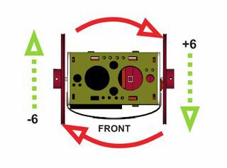
On B-ROBOT the steering command from the user is added to the motors output (one motor with a positive sign and the other with a negative sign). For example if the user sends the steering command 6 to turn to the right (from -10 to 10) we need to add 6 to the left motor value and subtract 6 from the right motor. If the robot is not moving forward or backwards, the result of the steering command is a spin of the robot
Step 2: What About the Remote Control?
We wanted B-ROBOT to be controlled by the user from almost any existing device, but we don´t want to develop a lot of different interfaces for different systems (Android, IOS, PC-windows…). Moreover, we decided to use existing (and powerful) protocols to control “things” and we found (some years ago) a protocol called OSC(Open Sound Control, more info here) used to control musical instruments like synthesizers. Very visual and powerful (we can display volume control, equalizers, lights…and create our own). To remotely control B-robot, we use OSC protocol over an Internet connection (Wifi module) using UDP packets. This is a lightweight and efficient way to send commands to our Robots!. We could also personalize the Interface we are using in our device so we will be able to control anything! (well…almost) What we need to do is to implement a lightweight library for Arduino in order to support this protocol (easy). We only use a subset of the OSC protocol to keep things small.
More info in the jjrobots webpage
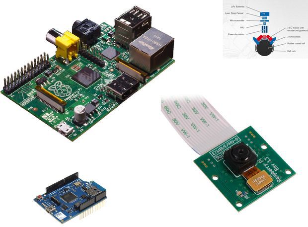
Step 3: FIRST! Check You Have Everything You Need
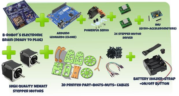
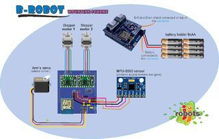
- B-ROBOT electronic brain shield (or create your own PCB board using the info available here)
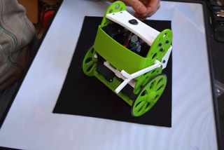
- B-Robot 3D printed plastic parts (STL models available here)
- Arduino LEONARDO
- 2x Stepper motor DRIVER (A4988)
- IMU MPU-6050 (gyro+accelerometer)
- 2x NEMA 17 stepper motors (40mm length, example:42BYGHW609)
- 8xAA battery holder (for NiMh or alkaline batteries)
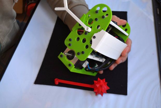
- OPTIONAL: Mini servo (21g) to move the arm (this is a fun feature)
The easy way to get everything is buying from us (and that encourages us to keep doing these robots) here (plus bolts, nuts, strap…)
HINT:
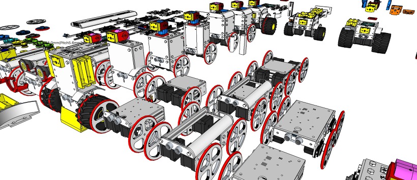
We are working on other robots that are using the same electronics and ancillary elements. If you get the items above you will be capable of assemble new different robots soon. Take a look to them at the last step
Step 4: Programming the ARDUINO LEONARDO

a) Install the Arduino IDE on your PC from (skip this step if you have arduino already installed)
This B-robot code has been tested and developed on IDE version 1.6.5
b) Install the libraries (https://github.com/jjrobots/B-ROBOT/tree/master/libraries) Copy the folders inside the /libraries into the Arduino/libraries folder on your hard drive
JJROBOTS_BROBOT
JJROBOTS_OSC
I2Cdev
MPU6050
c) Get the main CODE (https://github.com/jjrobots/B-ROBOT/tree/master/BROBOT).
d) Compile and send the code to the Arduino Leonardo:
- Open your Arduino IDE
- Open the main code in /BROBOT/BROBOT.ino
- Connect your Leonardo board with the USB to the PC
- Note: If this is the first time you connect a Leonardo board to your PC maybe you will need to install the driver.
- Select the board Leonardo (tools->board)
- Select the serial port that appears on the tools->Serial port
- Send the code to the board
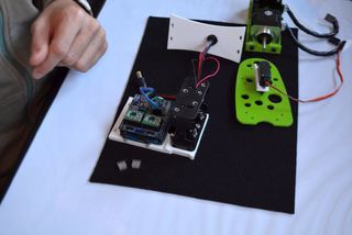
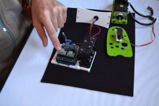
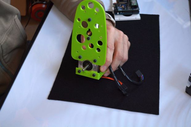
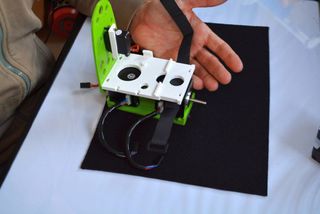
Step 5: Assemble the B-robot Frame+ Ancillary Elements
Step 6: (Optional But Recommended) Controlling the B-robot Using WIFI
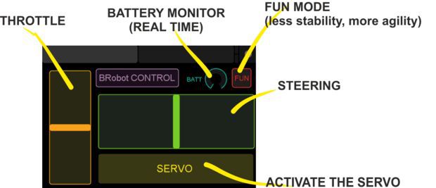
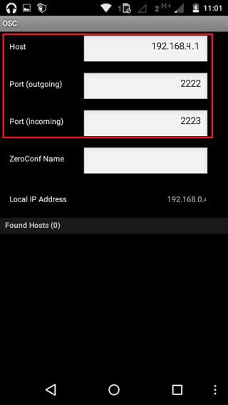
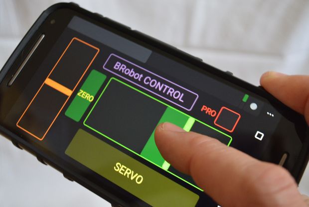
Setting up the TouchOSC software: If you are going to use the Touch OSC software to control the B-robot (and according to the current B-robot´s CODE available for the Arduino Leonardo), you will need to set these parameters in the TouchOSC like is shown in the images above.
Download the B-robot control layout (you can modify it if you want to) and install it using the OSCtouch APP
LINK: OSC layout used to control B-robot
Once the B.robot is switched on, a new WIFI signal will appear: “JJROBOTS-XX”. You will need to connect the controlling device to this network using the default WIFI password: 87654321
An OSC control software alternative: OSCillation and how to use it (Thanks Patrick!)
Step 7: Powering Up the B-robot:
- Lay down the B-robot on a static horizontal position in order to let it calibrate itself after powering it up.
- Turn the B-robot ON
- Let the B-robot 10 seconds to calibrate itself. Once self-calibrated, B-robot will spin its wheels a little.
- Time to stand up!: Use its arm or help it to stand up.
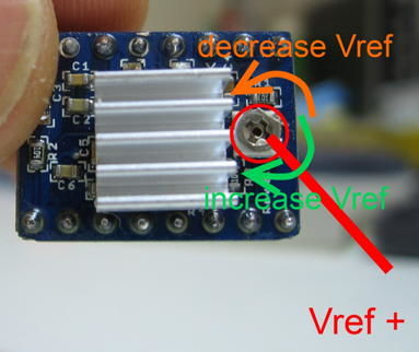
HINT: If the stepper motors do not have enough power to spin the wheels, try to adjust the current output in the A4988 stepper motor drivers rotating the screw indicated in the photo
QUESTIONS?
have a look to the B-robot forum
Step 8:

Other robots created (or under the last stage of development) which use the same electronics and ancillary elements.