How does it work?
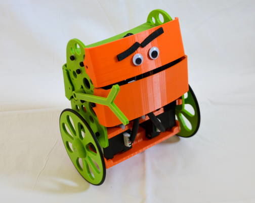
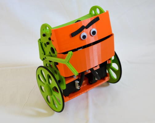
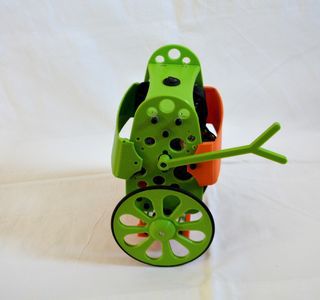
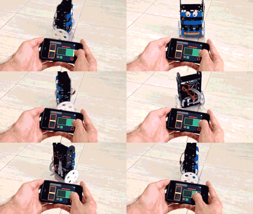
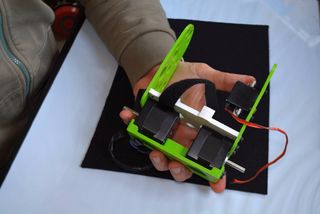
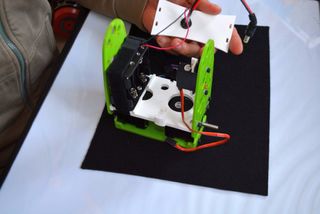
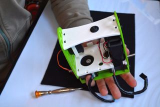
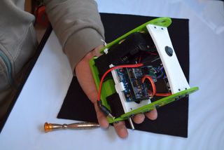
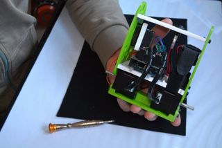
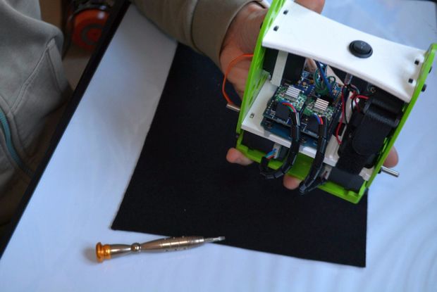
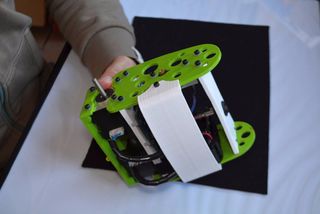
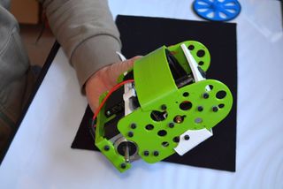
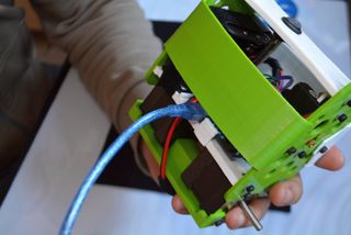
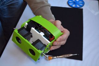
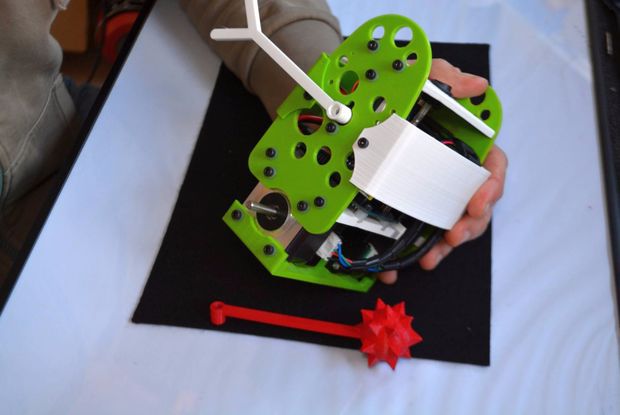
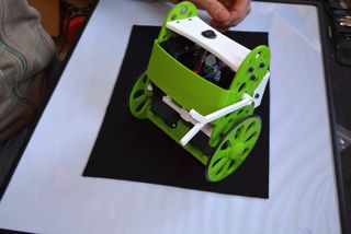
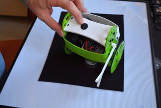
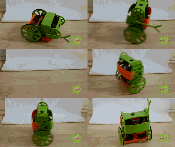
B-ROBOT EVO is a remotely controlled self balancing arduino robot created with 3D printed parts. With only two wheels, B-ROBOT is able to maintain its balance all the time by using his internal sensors and driving the motors. You can control your Robot, making him move or spin, by sending commands via a Smartphone, Tablet or PC while it maintains its balance.
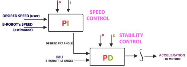
This self balancing robot reads his inertial sensors (accelerometers and gyroscopes integrated on the MPU6000 chip) 200 times per second. He calculates his attitude (angle with respect to the horizon) and compares this angle with the target angle (0º if he wants to maintain balance without moving, or a positive or negative angle if he wants to move forward or backwards). Using the difference between the target angle (let’s say 0º) and actual angle (let’s say 3º) he drives a Control System to send the right commands to the motors to maintain his balance. The commands to the motors are accelerations. For example if the robot is tilted forward (angle of robot is 3º) then he sends a command to the motors to accelerate forward until this angle is reduced to zero to preserve the balance.
Step 1: A Bit More in Depth…
The physical problem that B-ROBOT solves is called the Inverted Pendulum. This is the same mechanism you need to balance an umbrella above your hand. The pivot point is under the center of mass of the object. More information on Inverted Pendulum here. The mathematical solution to the problem is not easy but we don’t need to understand it in order to solve our robot´s balance issue. What we need to know is how should do to restore the robot´s balance so we can implement a Control Algorithm to resolve the problem.
A Control System is very useful in Robotics (an Industrial automation). Basically it´s a code that receives information from sensors and target commands as inputs and creates, in consequence, output signals to drive the Robot actuators (the motors in our example) in order to regulate the system. We are using a PID controller (Proportional + Derivative + Integral). This type of control has 3 constants to adjust kP,kD,kI. From Wikipedia: “A PID controller calculates an ‘error’ value as the difference between a measured [Input] and a desired setpoint. The controller attempts to minimize the error by adjusting [an Output].” So, you tell the PID what to measure (the “Input”),where you want that measurement to be (the “Setpoint”,) and the variable you wish to adjust to make that happen (the “Output”.)
The PID then adjusts the output trying to make the input equal the setpoint. For reference, a water tank we want to fill up to a level, the Input, Setpoint, and Output would be the level according to the water level sensor, the desired water level and the water pumped into the tank. kP is the Proportional part and is the main part of the control, this part is proportional to the error. kD is the Derivative part and is applied to the derivative of the error. This part depends on the dynamics of the system (depends on the robot,´s weight motors, inertias…). The last one, kI is applied to the integral of the error and is used to reduce steady errors, it is like a trim on the final output (think in the trim buttons on an RC car steering wheel to make the car go totally straight, kI removes the offset between the target required and the actual value).
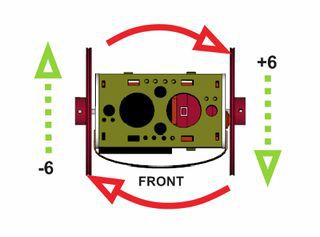
On B-ROBOT the steering command from the user is added to the motors output (one motor with a positive sign and the other with a negative sign). For example if the user sends the steering command 6 to turn to the right (from -10 to 10) we need to add 6 to the left motor value and subtract 6 from the right motor. If the robot is not moving forward or backwards, the result of the steering command is a spin of the robot
Step 2: What About the Remote Control?
We wanted B-ROBOT to be controlled by the user from almost any existing device, but we don´t want to develop a lot of different interfaces for different systems (Android, IOS, PC-windows…). Moreover, we decided to use existing (and powerful) protocols to control “things” and we found (some years ago) a protocol called OSC(Open Sound Control, more info here) used to control musical instruments like synthesizers. Very visual and powerful (we can display volume control, equalizers, lights…and create our own). To remotely control B-robot, we use OSC protocol over an Internet connection (Wifi module) using UDP packets. This is a lightweight and efficient way to send commands to our Robots!. We could also personalize the Interface we are using in our device so we will be able to control anything! (well…almost) What we need to do is to implement a lightweight library for Arduino in order to support this protocol (easy). We only use a subset of the OSC protocol to keep things small.
More info in the jjrobots webpage
Step 3: FIRST! Check You Have Everything You Need
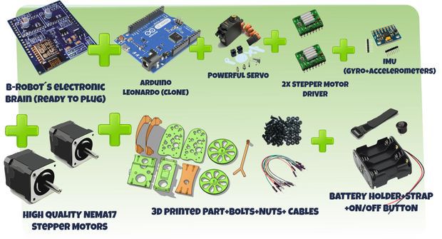
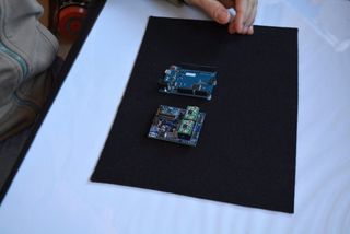
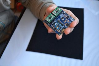
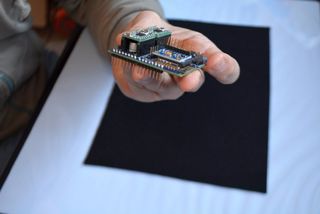
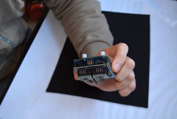
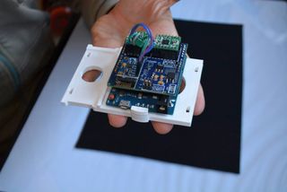
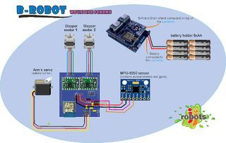
- B-ROBOT electronic brain shield (or create your own PCB board using the info available here)
- B-Robot 3D printed plastic parts (STL models available here)
- Arduino LEONARDO
- 2x Stepper motor DRIVER (A4988)
- IMU MPU-6050 (gyro+accelerometer)
- 2x NEMA 17 stepper motors (40mm length, example:42BYGHW609)
- 8xAA battery holder (for NiMh or alkaline batteries)
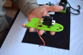
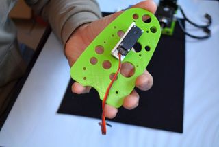
- OPTIONAL: Mini servo (21g) to move the arm (this is a fun feature)
The easy way to get everything is buying from us (and that encourages us to keep doing these robots) here (plus bolts, nuts, strap…)
HINT:
We are working on other robots that are using the same electronics and ancillary elements. If you get the items above you will be capable of assemble new different robots soon. Take a look to them at the last step
Step 4: Programming the ARDUINO LEONARDO
a) Install the Arduino IDE on your PC from (skip this step if you have arduino already installed)
This B-robot code has been tested and developed on IDE version 1.6.5
b) Install the libraries (https://github.com/jjrobots/B-ROBOT/tree/master/libraries) Copy the folders inside the /libraries into the Arduino/libraries folder on your hard drive
JJROBOTS_BROBOT
JJROBOTS_OSC
I2Cdev
MPU6050
c) Get the main CODE (https://github.com/jjrobots/B-ROBOT/tree/master/BROBOT).
d) Compile and send the code to the Arduino Leonardo:
- Open your Arduino IDE
- Open the main code in /BROBOT/BROBOT.ino
- Connect your Leonardo board with the USB to the PC
- Note: If this is the first time you connect a Leonardo board to your PC maybe you will need to install the driver.
- Select the board Leonardo (tools->board)
- Select the serial port that appears on the tools->Serial port
- Send the code to the board
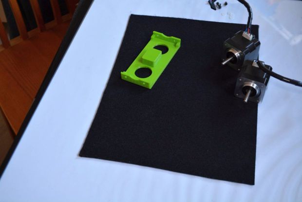
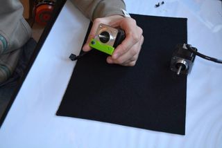
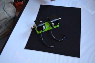
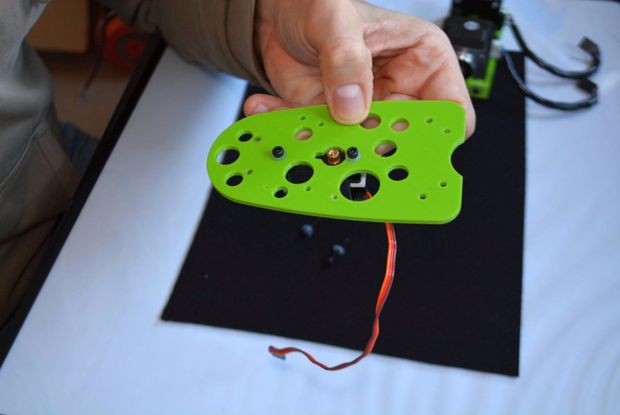
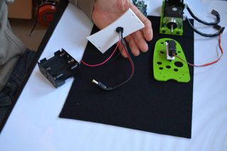
Step 5: Assemble the B-robot Frame+ Ancillary Elements
Step 6: (Optional But Recommended) Controlling the B-robot Using WIFI
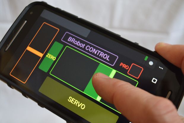
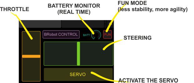
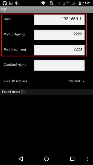
Setting up the TouchOSC software: If you are going to use the Touch OSC software to control the B-robot (and according to the current B-robot´s CODE available for the Arduino Leonardo), you will need to set these parameters in the TouchOSC like is shown in the images above.
Download the B-robot control layout (you can modify it if you want to) and install it using the OSCtouch APP
LINK: OSC layout used to control B-robot
Once the B.robot is switched on, a new WIFI signal will appear: “JJROBOTS-XX”. You will need to connect the controlling device to this network using the default WIFI password: 87654321
An OSC control software alternative: OSCillation and how to use it (Thanks Patrick!)
Step 7: Powering Up the B-robot:
- Lay down the B-robot on a static horizontal position in order to let it calibrate itself after powering it up.
- Turn the B-robot ON
- Let the B-robot 10 seconds to calibrate itself. Once self-calibrated, B-robot will spin its wheels a little.
- Time to stand up!: Use its arm or help it to stand up.
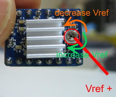
HINT: If the stepper motors do not have enough power to spin the wheels, try to adjust the current output in the A4988 stepper motor drivers rotating the screw indicated in the photo

