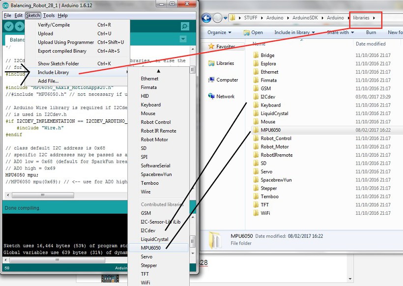
The Arduino SDK https://www.arduino.cc/en/Main/Software has been updated since I last worked on this, and the latest version gave me this error when compiling.
This was due to where the libraries were.
libraries\MPU6050\xxxI2Cdev.cpp.o (symbol from plugin): In function `I2Cdev::I2Cdev()’:
(.text+0x0): multiple definition of `I2Cdev::I2Cdev()’
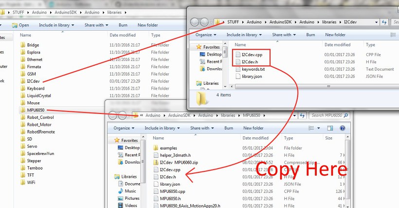
You won’t get an error if you put the header files in with the program file like so
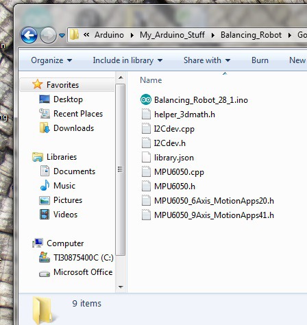
But if like me you prefer to keep your libraries in the Arduino Libraries folder
and add them using the Include Library tab like this
Then
because the header file MPU6050_6Axis_MotionApps20.h already includes (#include”I2Cdev.h”)
#ifndef _MPU6050_6AXIS_MOTIONAPPS20_H_
#define _MPU6050_6AXIS_MOTIONAPPS20_H_
#include “I2Cdev.h”
#include “helper_3dmath.h”
// MotionApps 2.0 DMP implementation, built using the MPU-6050EVB evaluation board
#define MPU6050_INCLUDE_DMP_MOTIONAPPS20
#include “MPU6050.h”
you may see the above error. The compiler looks for I2Cdev.h in the MPU6050 folder
but its not there! So copy I2Cdev.cpp & I2Cdev.h from I2Cdev Folder to
the MPU6050 Folder then add libraries….
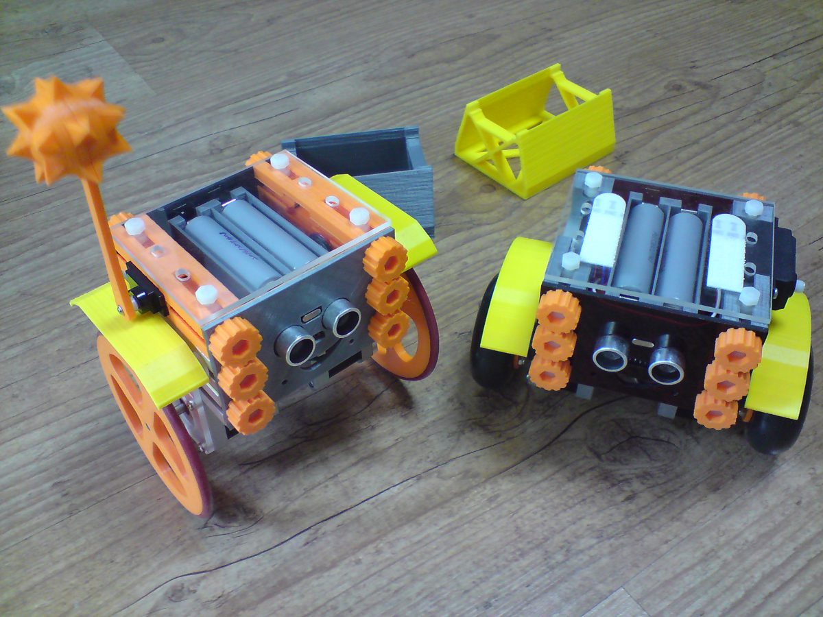
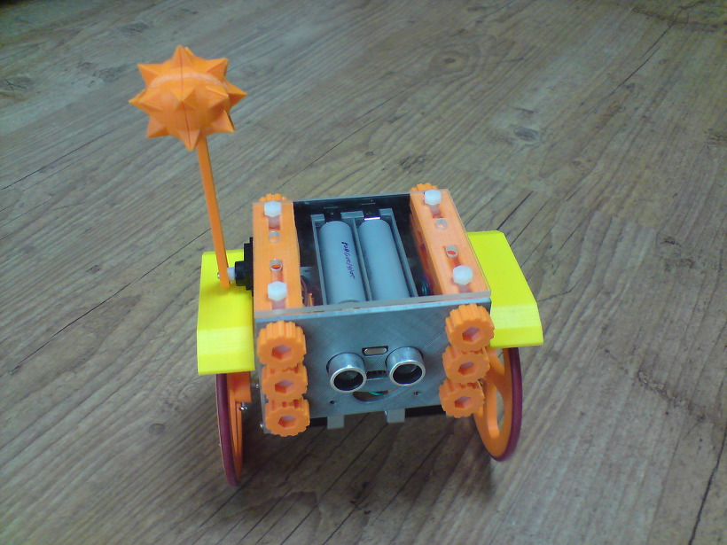
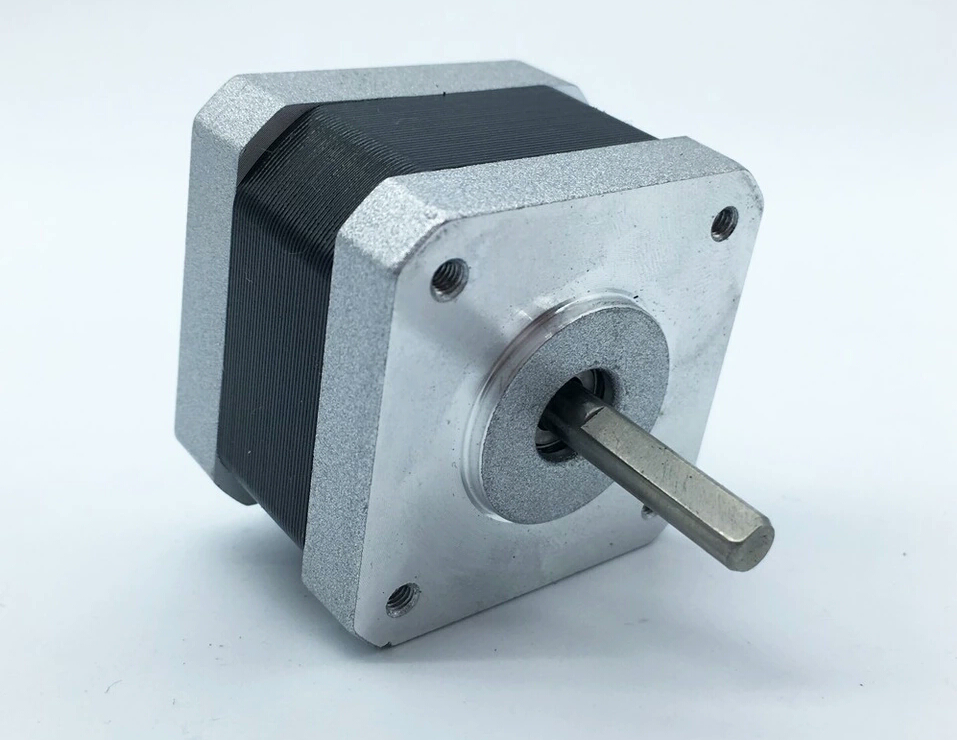
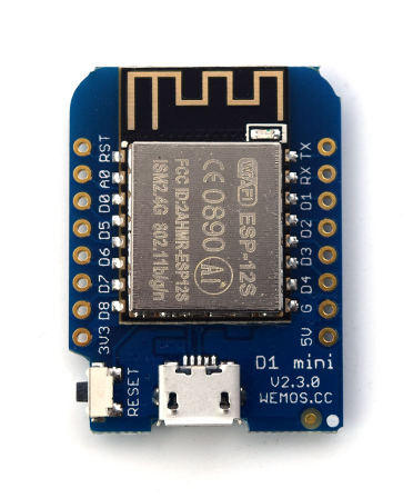
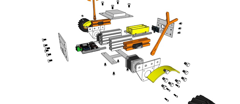
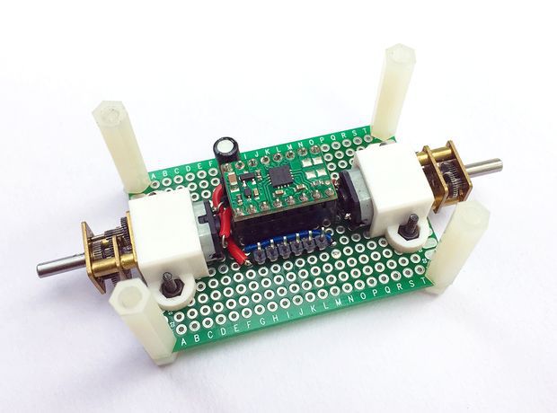
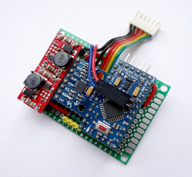
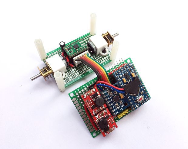
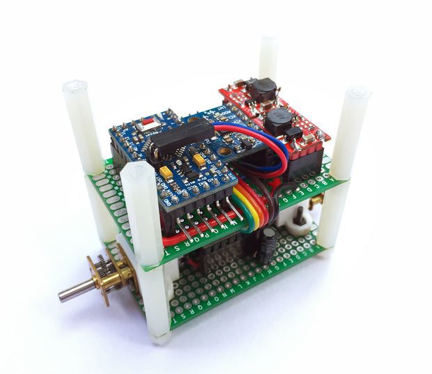
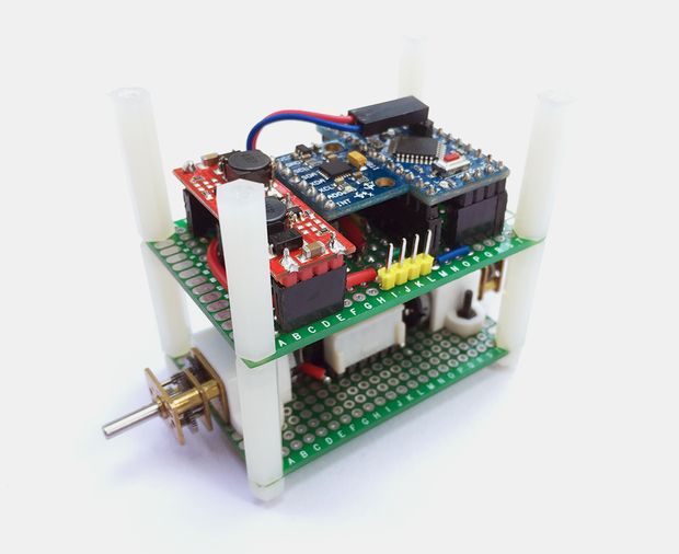
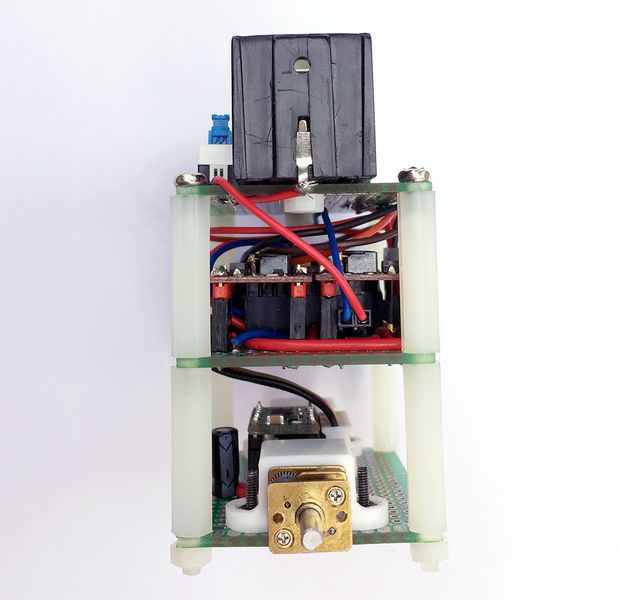
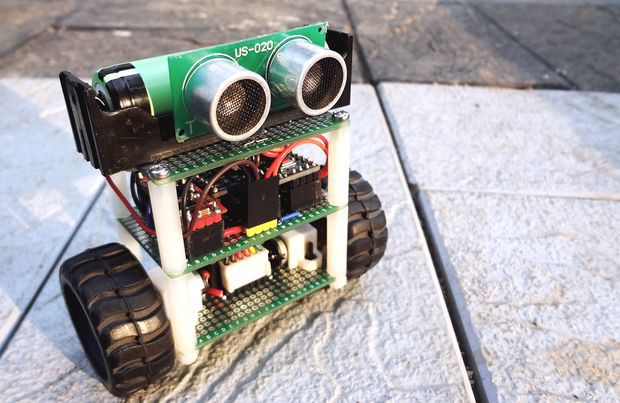
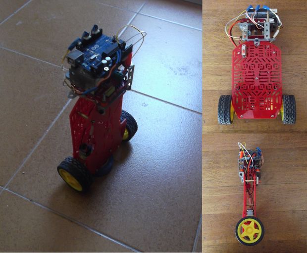
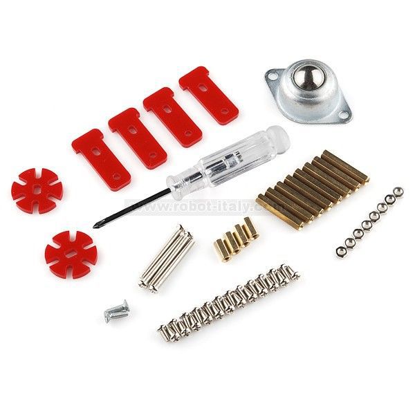
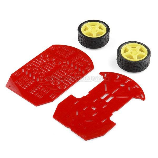
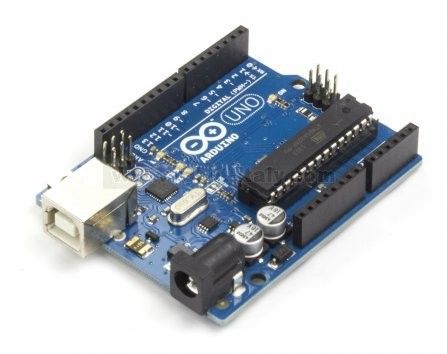
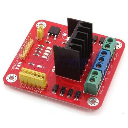
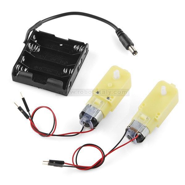
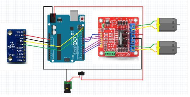
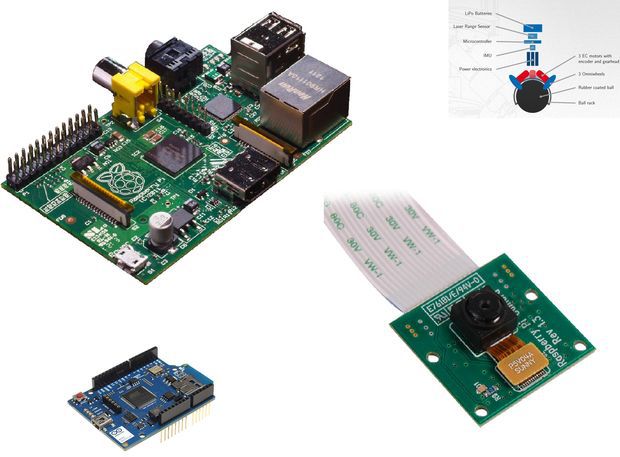
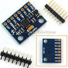
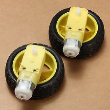
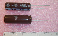
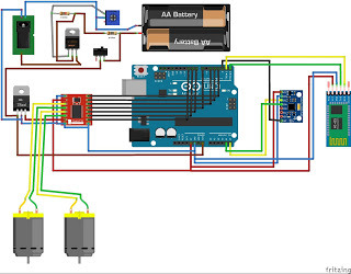
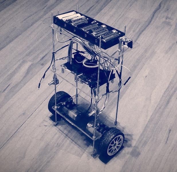
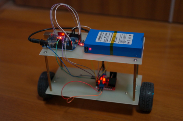
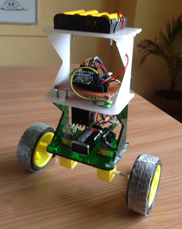
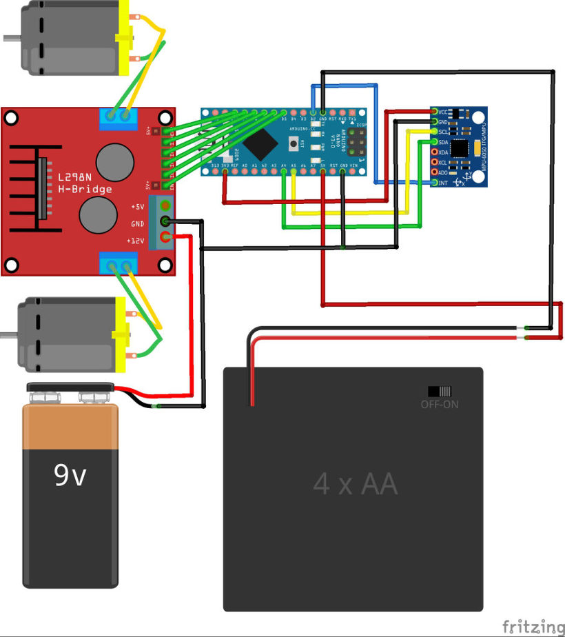
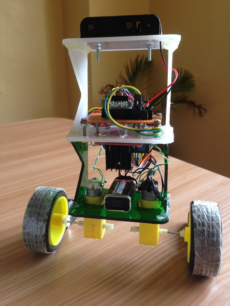
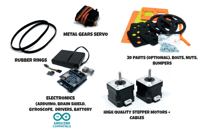
Shopping list of objects you will need.
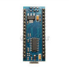
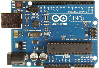
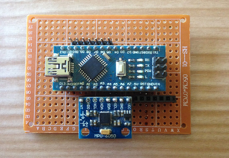
1. Compatible Nano V3.0 – ATmega328
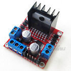
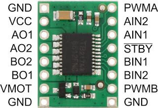
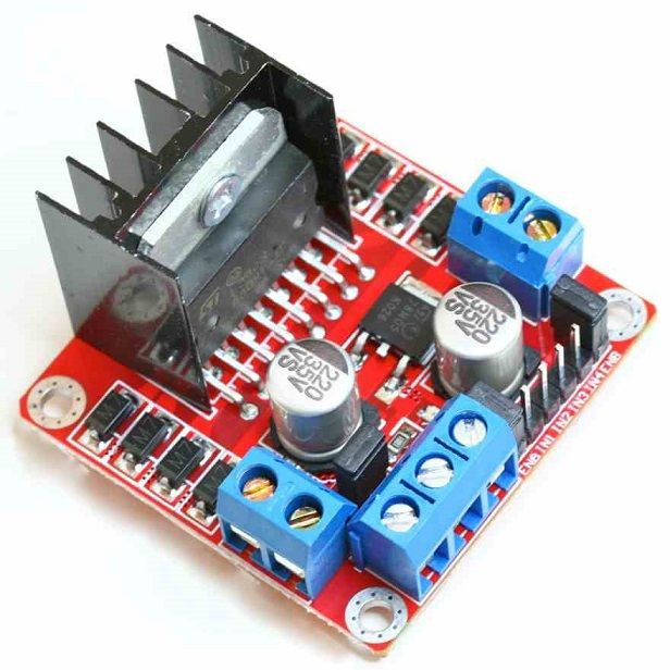
2. L298N DC Stepper Motor Dual H Bridge
4. SYB-170 Breadboard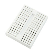
// Most of this code is other peoples read below!!
// the bits I have hacked are indicated thusly//********************************************************************************************************************************************************
// MY STUFF
// i found PlyAlex https://www.youtube.com/watch?v=nlXqIe9-R7s not a little helpful
//
// if you get the ERROR NO LIBRARY FOUND edit sketch book location in File-> Preferences
// default location of sketch book is not where you think it is.
// Most of this code is other peoples read below!!
// the bits I have hacked are indicated thusly
//********************************************************************************************************************************************************
// MY STUFF
// i found PlyAlex https://www.youtube.com/watch?v=nlXqIe9-R7s not a little helpful
//
// if you get the ERROR NO LIBRARY FOUND edit sketch book location in File-> Preferences
// default location of sketch book is not where you think it is.
//*********************************************************************************************************************************************************
// I2C device class (I2Cdev) demonstration Arduino sketch for MPU6050 class using DMP (MotionApps v2.0)
// 6/21/2012 by Jeff Rowberg <jeff@rowberg.net>
// Updates should (hopefully) always be available at https://github.com/jrowberg/i2cdevlib
//
// Changelog:
// 2013-05-08 – added seamless Fastwire support
// – added note about gyro calibration
// 2012-06-21 – added note about Arduino 1.0.1 + Leonardo compatibility error
// 2012-06-20 – improved FIFO overflow handling and simplified read process
// 2012-06-19 – completely rearranged DMP initialization code and simplification
// 2012-06-13 – pull gyro and accel data from FIFO packet instead of reading directly
// 2012-06-09 – fix broken FIFO read sequence and change interrupt detection to RISING
// 2012-06-05 – add gravity-compensated initial reference frame acceleration output
// – add 3D math helper file to DMP6 example sketch
// – add Euler output and Yaw/Pitch/Roll output formats
// 2012-06-04 – remove accel offset clearing for better results (thanks Sungon Lee)
// 2012-06-01 – fixed gyro sensitivity to be 2000 deg/sec instead of 250
// 2012-05-30 – basic DMP initialization working
/* ============================================
I2Cdev device library code is placed under the MIT license
Copyright (c) 2012 Jeff Rowberg
Permission is hereby granted, free of charge, to any person obtaining a copy
of this software and associated documentation files (the “Software”), to deal
in the Software without restriction, including without limitation the rights
to use, copy, modify, merge, publish, distribute, sublicense, and/or sell
copies of the Software, and to permit persons to whom the Software is
furnished to do so, subject to the following conditions:
The above copyright notice and this permission notice shall be included in
all copies or substantial portions of the Software.
THE SOFTWARE IS PROVIDED “AS IS”, WITHOUT WARRANTY OF ANY KIND, EXPRESS OR
IMPLIED, INCLUDING BUT NOT LIMITED TO THE WARRANTIES OF MERCHANTABILITY,
FITNESS FOR A PARTICULAR PURPOSE AND NONINFRINGEMENT. IN NO EVENT SHALL THE
AUTHORS OR COPYRIGHT HOLDERS BE LIABLE FOR ANY CLAIM, DAMAGES OR OTHER
LIABILITY, WHETHER IN AN ACTION OF CONTRACT, TORT OR OTHERWISE, ARISING FROM,
OUT OF OR IN CONNECTION WITH THE SOFTWARE OR THE USE OR OTHER DEALINGS IN
THE SOFTWARE.
===============================================
*/
// I2Cdev and MPU6050 must be installed as libraries, or else the .cpp/.h files
// for both classes must be in the include path of your project
#include “I2Cdev.h”
#include “MPU6050_6Axis_MotionApps20.h”
//#include “MPU6050.h” // not necessary if using MotionApps include file
// Arduino Wire library is required if I2Cdev I2CDEV_ARDUINO_WIRE implementation
// is used in I2Cdev.h
#if I2CDEV_IMPLEMENTATION == I2CDEV_ARDUINO_WIRE
#include “Wire.h”
#endif
// class default I2C address is 0x68
// specific I2C addresses may be passed as a parameter here
// AD0 low = 0x68 (default for SparkFun breakout and InvenSense evaluation board)
// AD0 high = 0x69
MPU6050 mpu;
//MPU6050 mpu(0x69); // <– use for AD0 high
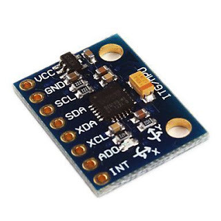
/* =========================================================================
NOTE: In addition to connection 3.3v, GND, SDA, and SCL, this sketch
depends on the MPU-6050’s INT pin being connected to the Arduino’s
external interrupt #0 pin. On the Arduino Uno and Mega 2560, this is
digital I/O pin 2.
* ========================================================================= */
/* =========================================================================
NOTE: Arduino v1.0.1 with the Leonardo board generates a compile error
when using Serial.write(buf, len). The Teapot output uses this method.
The solution requires a modification to the Arduino USBAPI.h file, which
is fortunately simple, but annoying. This will be fixed in the next IDE
release. For more info, see these links:
http://arduino.cc/forum/index.php/topic,109987.0.html
http://code.google.com/p/arduino/issues/detail?id=958
* ========================================================================= */
// uncomment “OUTPUT_READABLE_QUATERNION” if you want to see the actual
// quaternion components in a [w, x, y, z] format (not best for parsing
// on a remote host such as Processing or something though)
//#define OUTPUT_READABLE_QUATERNION
// uncomment “OUTPUT_READABLE_EULER” if you want to see Euler angles
// (in degrees) calculated from the quaternions coming from the FIFO.
// Note that Euler angles suffer from gimbal lock (for more info, see
// http://en.wikipedia.org/wiki/Gimbal_lock)
//#define OUTPUT_READABLE_EULER
// uncomment “OUTPUT_READABLE_YAWPITCHROLL” if you want to see the yaw/
// pitch/roll angles (in degrees) calculated from the quaternions coming
// from the FIFO. Note this also requires gravity vector calculations.
// Also note that yaw/pitch/roll angles suffer from gimbal lock (for
// more info, see: http://en.wikipedia.org/wiki/Gimbal_lock)
#define OUTPUT_READABLE_YAWPITCHROLL
// uncomment “OUTPUT_READABLE_REALACCEL” if you want to see acceleration
// components with gravity removed. This acceleration reference frame is
// not compensated for orientation, so +X is always +X according to the
// sensor, just without the effects of gravity. If you want acceleration
// compensated for orientation, us OUTPUT_READABLE_WORLDACCEL instead.
//#define OUTPUT_READABLE_REALACCEL
// uncomment “OUTPUT_READABLE_WORLDACCEL” if you want to see acceleration
// components with gravity removed and adjusted for the world frame of
// reference (yaw is relative to initial orientation, since no magnetometer
// is present in this case). Could be quite handy in some cases.
//#define OUTPUT_READABLE_WORLDACCEL
// uncomment “OUTPUT_TEAPOT” if you want output that matches the
// format used for the InvenSense teapot demo
//#define OUTPUT_TEAPOT
#define LED_PIN 13 // (Arduino is 13, Teensy is 11, Teensy++ is 6)
bool blinkState = false;
// MPU control/status vars
bool dmpReady = false; // set true if DMP init was successful
uint8_t mpuIntStatus; // holds actual interrupt status byte from MPU
uint8_t devStatus; // return status after each device operation (0 = success, !0 = error)
uint16_t packetSize; // expected DMP packet size (default is 42 bytes)
uint16_t fifoCount; // count of all bytes currently in FIFO
uint8_t fifoBuffer[64]; // FIFO storage buffer
// orientation/motion vars
Quaternion q; // [w, x, y, z] quaternion container
VectorInt16 aa; // [x, y, z] accel sensor measurements
VectorInt16 aaReal; // [x, y, z] gravity-free accel sensor measurements
VectorInt16 aaWorld; // [x, y, z] world-frame accel sensor measurements
VectorFloat gravity; // [x, y, z] gravity vector
float euler[3]; // [psi, theta, phi] Euler angle container
float ypr[3]; // [yaw, pitch, roll] yaw/pitch/roll container and gravity vector
// packet structure for InvenSense teapot demo
uint8_t teapotPacket[14] = { ‘$’, 0x02, 0,0, 0,0, 0,0, 0,0, 0x00, 0x00, ‘\r’, ‘\n’ };
//*************************************************************************************************************************************************************************
// MY Variables
float OldP = 0; // Previous value used to calculate change in P // DELTA P
float P = 0; // Proportional component
float I = 0; // Integral just the sum of P over time
float OldI = 0; // previous value of I for calculation of Delta I
float D = 0; // Differential D = P – OldP
float bp = -60; // balance point
float pwm = 0; // value of Pulse Width Modulation to ENA ENB
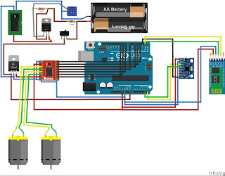
long a = 0; // L298N to IN 1 to 4
long b = 0; //
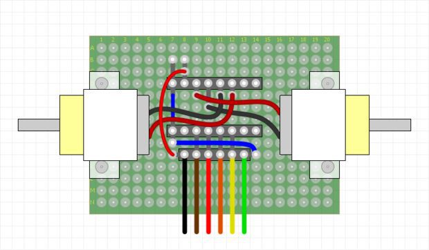
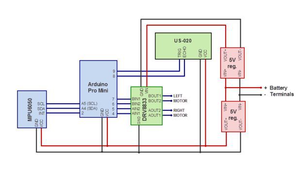
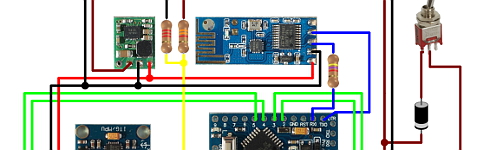
const int PinR1 = 5; // arduino pin 5 to l298 pin IN4
const int PinR2 = 6; // arduino pin 6 to l298 pin IN3
const int PinL1 = 7; // arduino pin 7 to l298 pin IN1
const int PinL2 = 8; // arduino pin 8 to l298 pin IN2
const int PwmR = 9; // arduino pin 9 to l298 pin ENB
const int PwmL = 10; // arduino pin 10 to l298 pin ENA
//****************************************************************************************************************************************************
// ================================================================
// === INTERRUPT DETECTION ROUTINE ===
// ================================================================
volatile bool mpuInterrupt = false; // indicates whether MPU interrupt pin has gone high
void dmpDataReady() {
mpuInterrupt = true;
}
// ================================================================
// === INITIAL SETUP ===
// ================================================================
void setup() {
//*********************************************************************************************************************************************************
// arduino to l298 pins hopefully self explanatory
pinMode(PinR1,OUTPUT);
pinMode(PinR2,OUTPUT);
pinMode(PinL1,OUTPUT);
pinMode(PinL2,OUTPUT);
//**********************************************************************************************************************************************************
// join I2C bus (I2Cdev library doesn’t do this automatically)
#if I2CDEV_IMPLEMENTATION == I2CDEV_ARDUINO_WIRE
Wire.begin();
TWBR = 24; // 400kHz I2C clock (200kHz if CPU is 8MHz)
#elif I2CDEV_IMPLEMENTATION == I2CDEV_BUILTIN_FASTWIRE
Fastwire::setup(400, true);
#endif
// initialize serial communication
// (115200 chosen because it is required for Teapot Demo output, but it’s
// really up to you depending on your project)
Serial.begin(57600);
while (!Serial); // wait for Leonardo enumeration, others continue immediately
// NOTE: 8MHz or slower host processors, like the Teensy @ 3.3v or Ardunio
// Pro Mini running at 3.3v, cannot handle this baud rate reliably due to
// the baud timing being too misaligned with processor ticks. You must use
// 38400 or slower in these cases, or use some kind of external separate
// crystal solution for the UART timer.
// initialize device
Serial.println(F(“Initializing I2C devices…”));
mpu.initialize();
// verify connection
Serial.println(F(“Testing device connections…”));
Serial.println(mpu.testConnection() ? F(“MPU6050 connection successful”) : F(“MPU6050 connection failed”));
//****************************************************************************************************************************************
// Commented out so that program dose not wait for imput,but gets straight to work
/*
// wait for ready
Serial.println(F(“\nSend any character to begin DMP programming and demo: “));
while (Serial.available() && Serial.read()); // empty buffer
while (!Serial.available()); // wait for data
while (Serial.available() && Serial.read()); // empty buffer again
*/
//*****************************************************************************************************************************************
// load and configure the DMP
Serial.println(F(“Initializing DMP…”));
devStatus = mpu.dmpInitialize();
// supply your own gyro offsets here, scaled for min sensitivity
//****************************************************************************************************************************************
// use calibration program to get your own values
mpu.setXGyroOffset(44);//(220);
mpu.setYGyroOffset(-21);//(76);
mpu.setZGyroOffset(-30);//(-85);
mpu.setXAccelOffset(-1875);//(1788); // 1688 factory default for my test chip
mpu.setYAccelOffset(-1426);
mpu.setZAccelOffset(2215);
//****************************************************************************************************************************************
// make sure it worked (returns 0 if so)
if (devStatus == 0) {
// turn on the DMP, now that it’s ready
Serial.println(F(“Enabling DMP…”));
mpu.setDMPEnabled(true);
// enable Arduino interrupt detection
Serial.println(F(“Enabling interrupt detection (Arduino external interrupt 0)…”));
attachInterrupt(0, dmpDataReady, RISING);
mpuIntStatus = mpu.getIntStatus();
// set our DMP Ready flag so the main loop() function knows it’s okay to use it
Serial.println(F(“DMP ready! Waiting for first interrupt…”));
dmpReady = true;
// get expected DMP packet size for later comparison
packetSize = mpu.dmpGetFIFOPacketSize();
} else {
// ERROR!
// 1 = initial memory load failed
// 2 = DMP configuration updates failed
// (if it’s going to break, usually the code will be 1)
Serial.print(F(“DMP Initialization failed (code “));
Serial.print(devStatus);
Serial.println(F(“)”));
}
// configure LED for output
pinMode(LED_PIN, OUTPUT);
}
// ================================================================
// === MAIN PROGRAM LOOP ===
// ================================================================
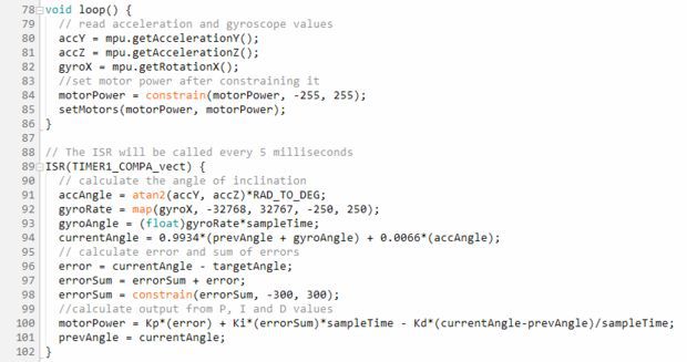
void loop() {
// if programming failed, don’t try to do anything
if (!dmpReady) return;
// wait for MPU interrupt or extra packet(s) available
while (!mpuInterrupt && fifoCount < packetSize) {
// other program behavior stuff here
}
// reset interrupt flag and get INT_STATUS byte
mpuInterrupt = false;
mpuIntStatus = mpu.getIntStatus();
// get current FIFO count
fifoCount = mpu.getFIFOCount();
// check for overflow (this should never happen unless our code is too inefficient)
if ((mpuIntStatus & 0x10) || fifoCount == 1024) {
// reset so we can continue cleanly
mpu.resetFIFO();
Serial.println(F(“FIFO overflow!”));
// otherwise, check for DMP data ready interrupt (this should happen frequently)
} else if (mpuIntStatus & 0x02) {
// wait for correct available data length, should be a VERY short wait
while (fifoCount < packetSize) fifoCount = mpu.getFIFOCount();
// read a packet from FIFO
mpu.getFIFOBytes(fifoBuffer, packetSize);
// track FIFO count here in case there is > 1 packet available
// (this lets us immediately read more without waiting for an interrupt)
fifoCount -= packetSize;
#ifdef OUTPUT_READABLE_YAWPITCHROLL
// display Euler angles in degrees
mpu.dmpGetQuaternion(&q, fifoBuffer);
mpu.dmpGetGravity(&gravity, &q);
mpu.dmpGetYawPitchRoll(ypr, &q, &gravity);
//*********************************************************************************************************************************************************************
// My Code
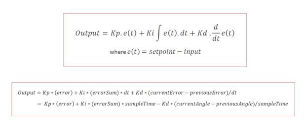
// PID control based on Pseudocode from https://en.wikipedia.org/wiki/PID_controller
// and the balance point idea from https://www.youtube.com/user/jmhrvy1947
OldP =P; // save value of P
P = (ypr[2] * 1000) + bp; // update P from MPU add bp to correct for balance
OldI = I; // save old I
I = I + (P * 0.05) ;
I = I + ((I – OldI)*2 ); // calulate new I
if( I > 250 ) I = 250; // LIMIT Stop I building up too high
if( I < -250 ) I = -250; // or too low value
D = P – OldP; // D differential change in P
pwm = ( P * 1 ) + ( I ) + ( D * 10 ) ; // P I D
a = 0;
b = 0;
if(pwm < 0){
a = 0;
b = 1;
bp = bp – 0.01;
digitalWrite(13, 0);
}
if(pwm > 0){
a = 1;
b = 0;
bp = bp + 0.01;
digitalWrite(13, 1);
}
/////////////////////////////
// remove sign from PWM as – value has no meaning
pwm = abs(pwm);
if ( pwm < 0) pwm = 0;
if ( pwm > 255) pwm = 255;
if(abs(ypr[2]) < abs(1.1)){
analogWrite(PwmR, pwm);
digitalWrite(PinR1, a);
digitalWrite(PinR2 ,b);
analogWrite(PwmL ,pwm);
digitalWrite(PinL1 ,a);
digitalWrite(PinL2 ,b);
}
else{
analogWrite(PwmR , 0);
analogWrite(PwmL , 0);
I = 0;
bp = -98;
delay(1000);
}
//********************************************************************************************************************************************************
#endif
}
}


 Q&A page


