How does this robot work? Can I adjust its behaviour? And modify it?
STEM education robot: In addition to being fun, the B-robot EVO 2 engage beginners and advanced students and incorporate many of the fundamental STEM concepts providing a learning platform that everyone enjoys
Bring a beverage can to the other side of the room not dropping it, race against other B-robots with different configurations and add-ons and understand what it is going on. The B-robot EVO 2 is a very versatile and fun STEM learning robot
CUSTOMISE YOUR ROBOT!
Create your own bumpers and personalise your B-robot with the online customisation tool on Thingiverse
Better than a bunch of photos we have created an Assembly guide video. Some steps, like how to program the Arduino, controlling your robot or Troubleshooting are listed below. The interactive 3D model will help you to get a good idea about how the B-robot EVO looks.
My B-robot is not responding to the command sent from my smartphone/tablet
Check you are connected to the JJROBOTS_XX netwrok using the correct password (by default: 87654321) and your device has not blocked the data traffic to the B-robot (stay always connected to the robot)
The IMU gets loose/ the i2C cable is too short
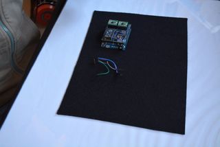
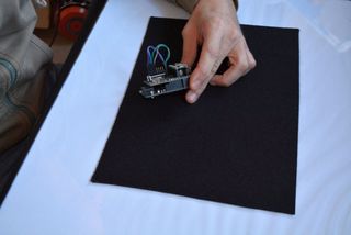
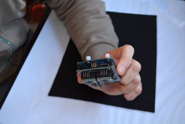
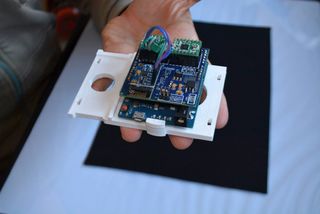
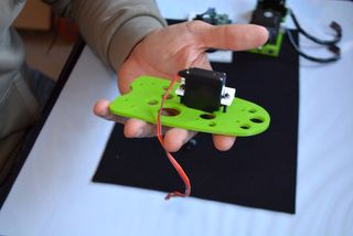
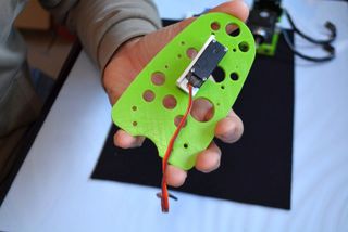
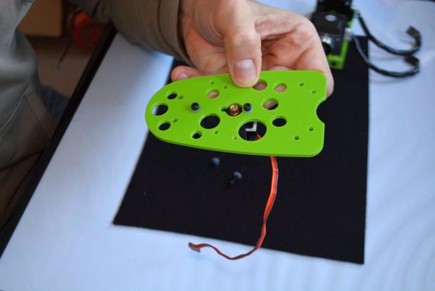
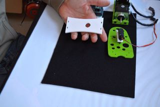
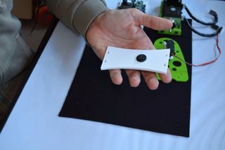
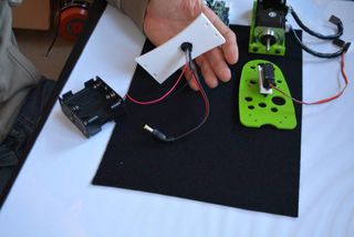
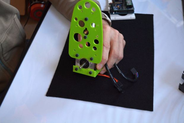
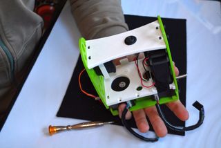
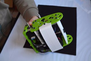
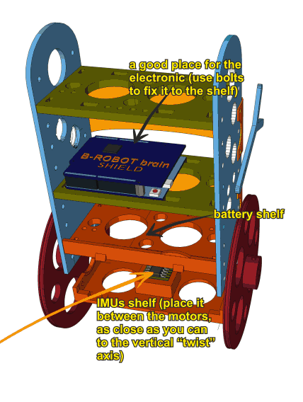
The gyroscope (IMU) is one of the most important element in this robot. It provides the current angle of the robot updating its value hundred times per second. The protocol used to send the data is quite sensitive to any electromagnetic interference so a very short cable is needed to connect the IMU and the Brain Shield. At the same time, vibrations create false angle measurements so we have to isolate the Brobot´s main frame vibrations from the IMU: that is the reason to use a double sided sticky pad to fix the IMU to the Brain Shield.
Place the IMU as indicated above: Close to the Brain Shield´s i2C connector. Bend the cable if needed. If you place the IMU as above, there should not be any lateral force pushing the IMU out of place
My B-robot lacks of power or fall without reason
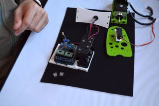
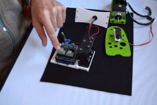
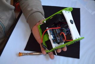
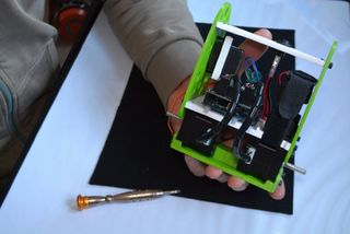
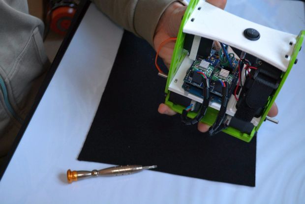
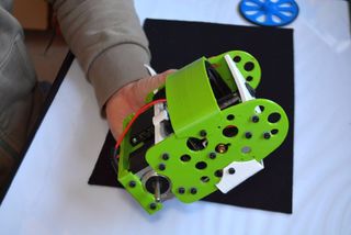
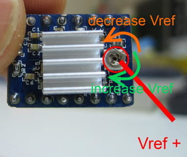
Adjust the current delivered by the stepper motors drivers. Use a screwdriver and gently rotate the screws indicated on the photo below. Rotating 10º-30º is more than enough.
Clockwise rotation: increase the power delivered to the motors
A4988 STEPPER MOTOR DRIVERS output current potentiometer
My B-robot can not stand up by itself.
If everything is ok, the B-robot only needs a little bit of help from the servo to stand up by itself. Take a look to the video below. If your robot does not behave like in the video, adjust the stepper motor drivers output power (instructions above). Keep in mind that the bumpers have two functions here: protect the electronics+robot and help it to stand up easily.
Video Player
DEBUG MODE
There is a DEBUG MODE inside the B-robot CODE. This MODE will allow you the debug the behaviour of the robot if you are having issues. Please, refer to the B-robot community if you have problems or questions.
Look at the sketch line “#define DEBUG 0″ and change the 0 to 1…8 depending on what info you want to get. Take a look to the CODE below:
//Serial.print(“\t”);
mpu.resetFIFO(); // We always reset FIFO
// We calculate the estimated robot speed:
// Estimated_Speed = angular_velocity_of_stepper_motors(combined) – angular_velocity_of_robot(angle measured by IMU)
actual_robot_speed_Old = actual_robot_speed;
actual_robot_speed = (speed_M1 + speed_M2)/2; // Positive: forward
int16_t angular_velocity = (angle_adjusted-angle_adjusted_Old)*90.0; // 90 is an empirical extracted factor to adjust for real units
int16_t estimated_speed = -actual_robot_speed_Old – angular_velocity; // We use robot_speed(t-1) or (t-2) to compensate the delay
estimated_speed_filtered = estimated_speed_filtered*0.95 + (float)estimated_speed*0.05;
// SPEED CONTROL: This is a PI controller.
// input:user throttle, variable: estimated robot speed, output: target robot angle to get the desired speed
//target_angle = (target_angle + speedPControl(estimated_speed_filtered,throttle,Kp_thr))/2.0; // Some filtering : Average with previous output
//target_angle = target_angle*0.3 + speedPIControl(dt,estimated_speed_filtered,throttle,Kp_thr,Ki_thr)*0.7; // Some filtering
target_angle = speedPIControl(dt,estimated_speed_filtered,throttle,Kp_thr,Ki_thr);
target_angle = constrain(target_angle,-max_target_angle,max_target_angle); // limited output
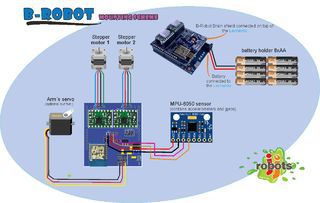
There are several options for motors: DC, Brushless, Steppers… We choose stepper motors because they have enough torque, you could connect the wheels directly without gears that generate some backslash (this is a common problem in balancing robots), they have good bearings and you will be able to control the speed of the motors with accuracy. In standard sizes these motors are cheap (we use the same motors used on a regular 3D printers) and the drivers are cheap and easy to interface with Arduino too.
Why you use a Wifi connection?
Using a Wifi connection allow us to work with a lot of devices (Smartphones, Tablets, PCs…) Bluetooth devices are cheaper but their range is usually shorter. Old devices are not supported and you could not connect it to Internet easily. The Wifi module that we recommend, allow us to create an Access Point, so you don’t need to use an existing Wifi infrastructure (cheap Wifi modules don´t let you do this). You can connect your device directly to the Robot anywhere but if you prefer you can hack it and use your own infrastructure therefore controlling your robot (or whatever you have created) over the Internet from any remote place in the world! (Cool, isn´t it?)
Why BROBOT?
Self balancing robots are fun to see and play. A self balancing robot requires sensors and control algorithms. You will find all the HOWTO and technical documents which explains the “behind the scenes” in JJROBOTS. Learn electronics and robotics creating your own BROBOT from scratch!.
There are some commercial solutions to the balancing robot, but here we want to share knowledge and thoughts. You can use the BROBOT parts to create more robots or gadgets, keep in mind all the devices used in a BROBOT are standard devices/electronics with a lot of potential. In the JJROBOTS community we want to show you how! You are now buying a self balancing robot, your are buying your own electronic and ancillary devices!
Thinking about creating a GPS self guidance robot? a modified version of BROBOT is your robot!
How much payload could carry BROBOT?
BROBOT could easily carry your soft-drink cans. We have tested with 500g of payload with success. More weight makes the robot more unstable but this could be fun also, isn’t it?
Why use stepper motors for a balancing robot?
There are several options for motors, DC, Brushless, Steppers… We choose stepper motors because they have enough torque, you could connect the wheels directly without gears that generate some backslash, they have good bearings and you could control the speed of the motors very precisely. Also they are cheap and the drivers too…
Could I use rechargeable batteries of Lipo batteries?
Yes, you could use standard AA batteries (alkaline recommended), AA rechargeable batteries (e.g. NiMh) or you could optionally use a 3S Lipo battery. Run Lipo batteries at your own responsibility.
What is the runtime of BROBOT?
With rechargeable AA batteries (e.g. Ni-Mh 2100mAh) you could expect around half to an hour of runtime
Could BROBOT work without the wifi module?
Yes, BROBOT could work and keep its stability. But, of course you could not control it without the module.
Could I change the name of the Wifi network that BROBOT generate?
Yes, on the configuration sketch you could change the name and also some other internet configurations. You could also connect BROBOT with your existing Wifi network
Is this a project for an Arduino beginner?
Well, BROBOT is not an easy “beginner project”, but it has a lot of documentation so you have a platform to grow your skills. You could first mount your BROBOT following the instructions and it should work OK, then you could start understanding some parts of the code and finally writing your own pieces of code…
For example it could be easily (there are tutorials for this) to write your code so the robot automatically move the arm and spin itself if you don’t send a command in 10 seconds…
More advanced hacks: Convert to a totally autonomous robot with obstacle avoiding adding a SONAR, convert to a follow line robot, and so on…
Why BROBOT electronics are not so cheap?
We are a really small startup (2 persons in our free time) and now we could only run small batch of electronics. As yo know the price of electronics drops quickly in high volume productions but we are starting… If we sell many boards and we could run more volume productions we will drop the prices!!. JJROBOTS didn´t born to get money, our spirit is to sell “good products” to found our next projects and spread the robotics knowledge
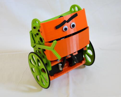
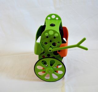
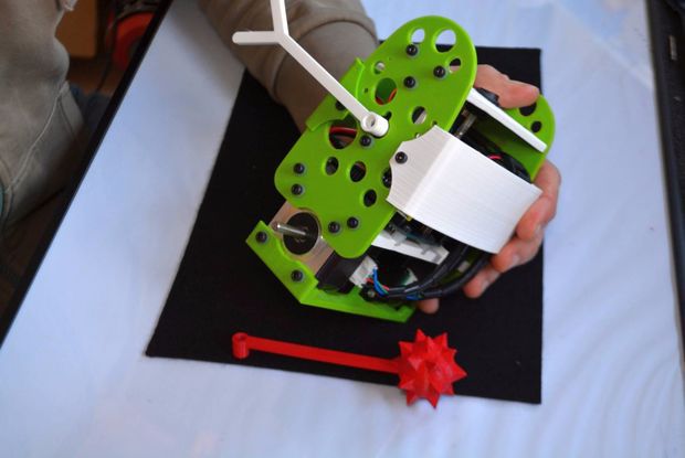
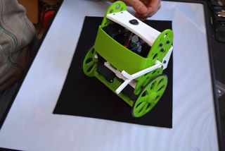
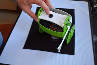
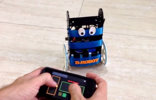
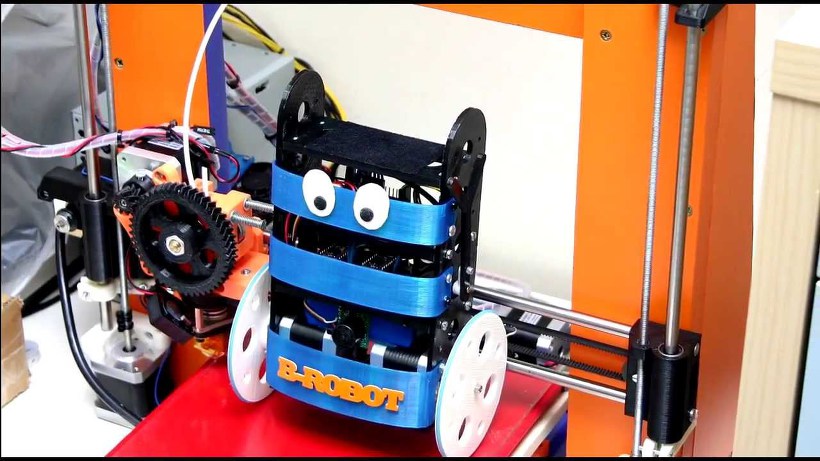
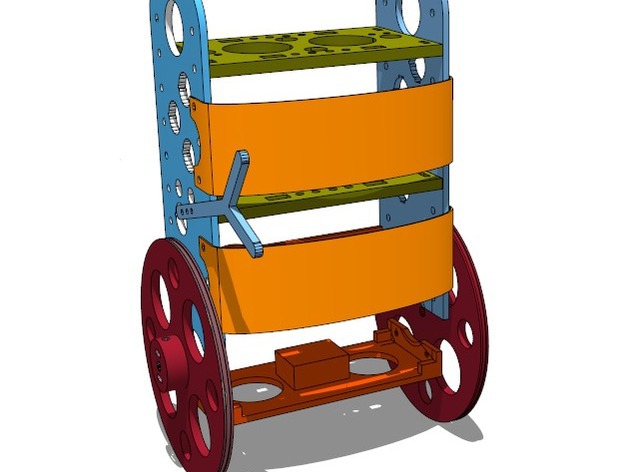
B-ROBOT EVO is a remotely controlled self balancing arduino robot created with 3D printed parts. With only two wheels, B-ROBOT is able to maintain its balance all the time by using his internal sensors and driving the motors. You can control your Robot, making him move or spin, by sending commands via a Smartphone, Tablet or PC while it maintains its balance.
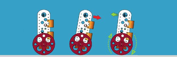
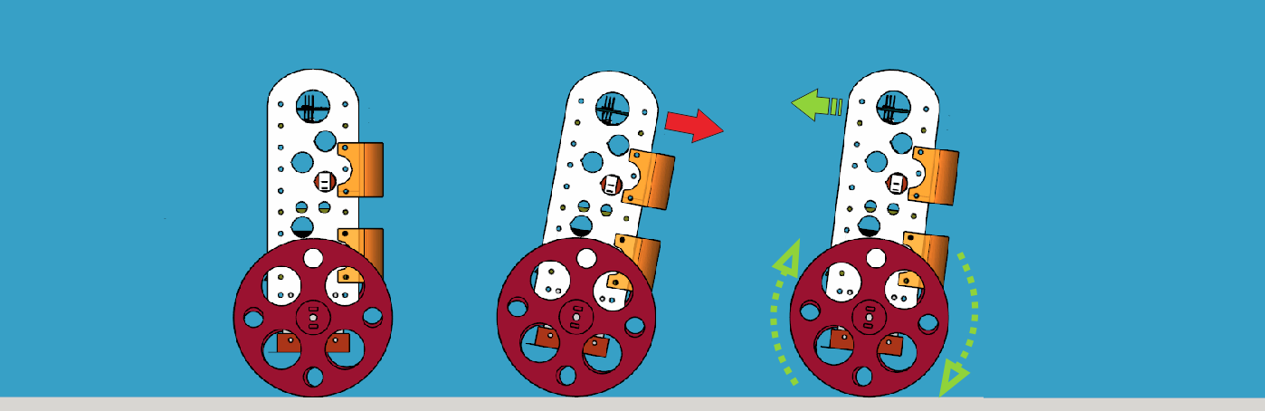
This self balancing robot reads his inertial sensors (accelerometers and gyroscopes integrated on the MPU6000 chip) 200 times per second. He calculates his attitude (angle with respect to the horizon) and compares this angle with the target angle (0º if he wants to maintain balance without moving, or a positive or negative angle if he wants to move forward or backwards). Using the difference between the target angle (let’s say 0º) and actual angle (let’s say 3º) he drives a Control System to send the right commands to the motors to maintain his balance. The commands to the motors are accelerations. For example if the robot is tilted forward (angle of robot is 3º) then he sends a command to the motors to accelerate forward until this angle is reduced to zero to preserve the balance.
Step 1: A Bit More in Depth…
The physical problem that B-ROBOT solves is called the Inverted Pendulum. This is the same mechanism you need to balance an umbrella above your hand. The pivot point is under the center of mass of the object. More information on Inverted Pendulum here. The mathematical solution to the problem is not easy but we don’t need to understand it in order to solve our robot´s balance issue. What we need to know is how should do to restore the robot´s balance so we can implement a Control Algorithm to resolve the problem.
A Control System is very useful in Robotics (an Industrial automation). Basically it´s a code that receives information from sensors and target commands as inputs and creates, in consequence, output signals to drive the Robot actuators (the motors in our example) in order to regulate the system. We are using a PID controller (Proportional + Derivative + Integral). This type of control has 3 constants to adjust kP,kD,kI. From Wikipedia: “A PID controller calculates an ‘error’ value as the difference between a measured [Input] and a desired setpoint. The controller attempts to minimize the error by adjusting [an Output].” So, you tell the PID what to measure (the “Input”),where you want that measurement to be (the “Setpoint”,) and the variable you wish to adjust to make that happen (the “Output”.)
The PID then adjusts the output trying to make the input equal the setpoint. For reference, a water tank we want to fill up to a level, the Input, Setpoint, and Output would be the level according to the water level sensor, the desired water level and the water pumped into the tank. kP is the Proportional part and is the main part of the control, this part is proportional to the error. kD is the Derivative part and is applied to the derivative of the error. This part depends on the dynamics of the system (depends on the robot,´s weight motors, inertias…). The last one, kI is applied to the integral of the error and is used to reduce steady errors, it is like a trim on the final output (think in the trim buttons on an RC car steering wheel to make the car go totally straight, kI removes the offset between the target required and the actual value).
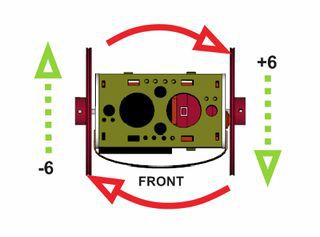
On B-ROBOT the steering command from the user is added to the motors output (one motor with a positive sign and the other with a negative sign). For example if the user sends the steering command 6 to turn to the right (from -10 to 10) we need to add 6 to the left motor value and subtract 6 from the right motor. If the robot is not moving forward or backwards, the result of the steering command is a spin of the robot
Step 2: What About the Remote Control?
We wanted B-ROBOT to be controlled by the user from almost any existing device, but we don´t want to develop a lot of different interfaces for different systems (Android, IOS, PC-windows…). Moreover, we decided to use existing (and powerful) protocols to control “things” and we found (some years ago) a protocol called OSC(Open Sound Control, more info here) used to control musical instruments like synthesizers. Very visual and powerful (we can display volume control, equalizers, lights…and create our own). To remotely control B-robot, we use OSC protocol over an Internet connection (Wifi module) using UDP packets. This is a lightweight and efficient way to send commands to our Robots!. We could also personalize the Interface we are using in our device so we will be able to control anything! (well…almost) What we need to do is to implement a lightweight library for Arduino in order to support this protocol (easy). We only use a subset of the OSC protocol to keep things small.
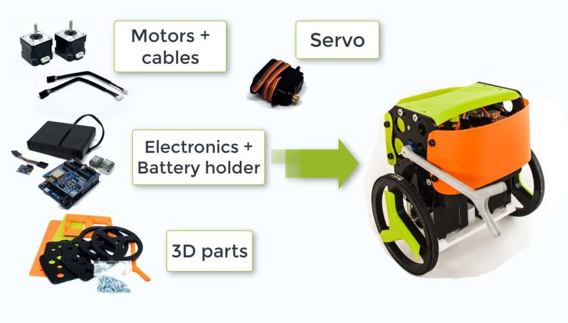
8xAA battery holder (for NiMh or alkaline batteries)
OPTIONAL: Mini servo (21g) to move the arm (this is a fun feature)
The easy way to get everything is buying from us (and that encourages us to keep doing these robots) here (plus bolts, nuts, strap…)
HINT:
We are working on other robots that are using the same electronics and ancillary elements. If you get the items above you will be capable of assemble new different robots soon. Take a look to them at the last step
Step 4: Programming the ARDUINO LEONARDO
a) Install the Arduino IDE on your PC from (skip this step if you have arduino already installed)
This B-robot code has been tested and developed on IDE version 1.6.5
b) Install the libraries (https://github.com/jjrobots/B-ROBOT/tree/master/libraries) Copy the folders inside the /libraries into the Arduino/libraries folder on your hard drive
JJROBOTS_BROBOT
JJROBOTS_OSC
I2Cdev
MPU6050
c) Get the main CODE (https://github.com/jjrobots/B-ROBOT/tree/master/BROBOT).
d) Compile and send the code to the Arduino Leonardo:
Open your Arduino IDE
Open the main code in /BROBOT/BROBOT.ino
Connect your Leonardo board with the USB to the PC
Note: If this is the first time you connect a Leonardo board to your PC maybe you will need to install the driver.
Select the board Leonardo (tools->board)
Select the serial port that appears on the tools->Serial port
Send the code to the board
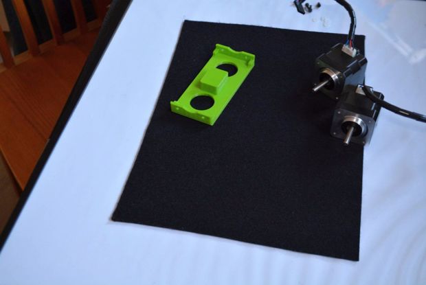
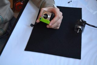
Step 5: Assemble the B-robot Frame+ Ancillary Elements
Step 6: (Optional But Recommended) Controlling the B-robot Using WIFI
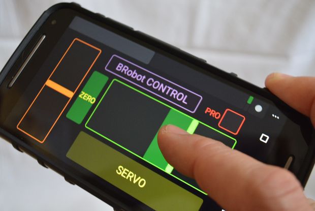
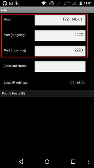
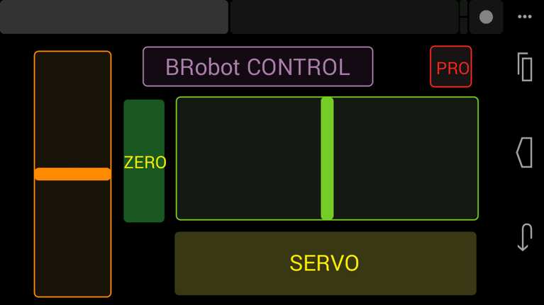
Setting up the TouchOSC software: If you are going to use the Touch OSC software to control the B-robot (and according to the current B-robot´s CODE available for the Arduino Leonardo), you will need to set these parameters in the TouchOSC like is shown in the images above.
Download the B-robot control layout (you can modify it if you want to) and install it using the OSCtouch APP
Once the B.robot is switched on, a new WIFI signal will appear: “JJROBOTS-XX”. You will need to connect the controlling device to this network using the default WIFI password: 87654321
An OSC control software alternative: OSCillation and how to use it (Thanks Patrick!)
Step 7: Powering Up the B-robot:
Lay down the B-robot on a static horizontal position in order to let it calibrate itself after powering it up.
Turn the B-robot ON
Let the B-robot 10 seconds to calibrate itself. Once self-calibrated, B-robot will spin its wheels a little.
Time to stand up!: Use its arm or help it to stand up.
HINT: If the stepper motors do not have enough power to spin the wheels, try to adjust the current output in the A4988 stepper motor drivers rotating the screw indicated in the photo
B-ROBOT is a remotely controlled self balancing arduino robot created with 3D printed parts. With only two wheels, B-ROBOT is able to maintain its balance all the time by using his internal sensors and driving the motors. You can control your Robot, making him move or spin, by sending commands via a Smartphone, Tablet or PC while it maintains its balance.
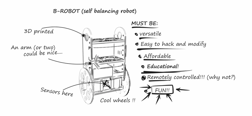
Above: the B-Robot “brainstorming” creation ideas
This self balancing robot reads his inertial sensors (accelerometers and gyroscopes integrated on the MPU6000 chip) 200 times per second. He calculates his attitude (angle with respect to the horizon) and compares this angle with the target angle (0º if he wants to maintain balance without moving, or a positive or negative angle if he wants to move forward or backwards). Using the difference between the target angle (let’s say 0º) and actual angle (let’s say 3º) he drives a Control System to send the right commands to the motors to maintain his balance. The commands to the motors are accelerations. For example if the robot is tilted forward (angle of robot is 3º)then he sends a command to the motors to accelerate forward until this angle is reduced to zero to preserve the balance.
Stable position leaning forward Correcting its tilt using motors
A bit more in depth…
The physical problem that B-ROBOT solves is called the Inverted Pendulum. This is the same mechanism you need to balance an umbrella above your hand. The pivot point is under the center of mass of the object. More information on Inverted Pendulum here. The mathematical solution to the problem is not easy but we don’t need to understand it in order to solve our robot´s balance issue. What we need to know is how should do to restore the robot´s balance so we can implement a Control Algorithm to resolve the problem.
A Control System is very useful in Robotics (an Industrial automation). Basically it´s a code that receives information from sensors and target commands as inputs and creates, in consequence, output signals to drive the Robot actuators (the motors in our example) in order to regulate the system. We are using a PID controller (Proportional + Derivative + Integral). This type of control has 3 constants to adjust kP,kD,kI.
From Wikipedia: “A PID controller calculates an ‘error’ value as the difference between a measured [Input] and a desired setpoint. The controller attempts to minimize the error by adjusting [an Output].”
So, you tell the PID what to measure (the “Input”) ,where you want that measurement to be (the “Setpoint”,) and the variable you wish to adjust to make that happen (the “Output”.) The PID then adjusts the output trying to make the input equal the setpoint.
For reference, a water tank we want to fill up to a level, the Input, Setpoint, and Output would be the level according to the water level sensor, the desired water level and the water pumped into the tank.
kP is the Proportional part and is the main part of the control, this part is proportional to the error. kD is the Derivative part and is applied to the derivative of the error. This part depends on the dynamics of the system (depends on the robot,´s weight motors, inertias…). The last one, kI is applied to the integral of the error and is used to reduce steady errors, it is like a trim on the final output (think in the trim buttons on an RC car steering wheel to make the car go totally straight, kI removes the offset between the target required and the actual value).
On B-ROBOT the steering command from the user is added to the motors output (one motor with a positive sign and the other with a negative sign). For example if the user sends the steering command 6 to turn to the right (from -10 to 10) we need to add 6 to the left motor value and subtract 6 from the right motor. If the robot is not moving forward or backwards, the result of the steering command is a spin of the robot.
Above: Top view of the B-ROBOT and the commands to the motors
B-robot control APP (thanks to Xuyen for this great contribution!)
We wanted B-ROBOT to be controlled by the user from almost any existing device, but we don´t want 😉 to develop a lot of different interfaces for different systems (Android, IOS, PC-windows…). Moreover, we decided to use existing (and powerful) protocols to control “things” and we found (some years ago) a protocol called OSC (Open Sound Control, more info here) used to control musical instruments like synthesizers. Very visual and powerful (we can display volume control, equalizers, lights…and create our own). To remotely control B-robot, we use OSC protocol over an Internet connection (Wifi module) using UDP packets. This is a lightweight and efficient way to send commands to our Robots!. We could also personalize the Interface we are using in our device so we will be able to control anything! (well…almost) What we need to do is to implement a lightweight library for Arduino in order to support this protocol (easy). We only use a subset of the OSC protocol to keep things small.
OSC interface on an Android Device.
controlling the B-ROBOT (the old version in this case)
More about the Control System…
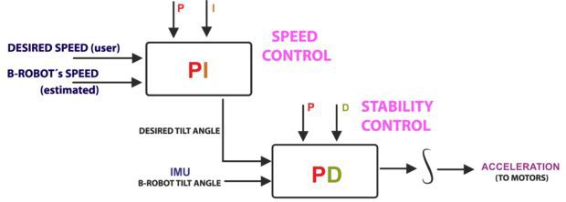
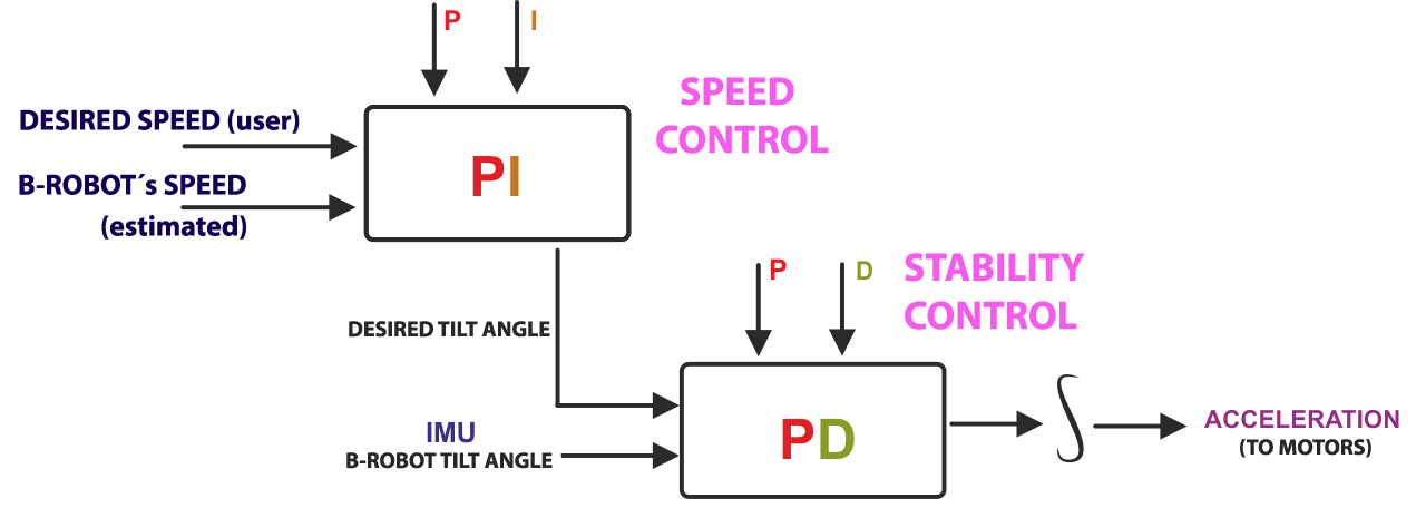
But things are a bit more complex… We have really two PID controllers in a cascade configuration (the output of one controller connected to the next one). The output controller is a speed controller and the inner controller is the stability controller.
ABOVE: B-ROBOT control algorithm loop
We could use only one stability controller (the second one) but this would mean that the control´s output would be the desired robot tilt angle, so the user would control the robot angle directly. The problem is that if the center of gravity is not perfectly located above the wheels axis , so the robot needs a little tilt angle to keep the balance and if the user sends a command of tilt=0 then the robot will maintain its balance whilst moving… When adding the second controller (speed controller) the system compensates automatically for this. The user sends a command to the robot speed=0 and this controller will send the “correct” tilt angle to the second controller (stability controller) to mantain the robot balanced and not moving! For the users it is much simpler to set the desired robot speed and the system will find the right robot angle to achieve this speed.
Now… How to create a self balancing robot like B-robot
There are several options for motors: DC, Brushless, Steppers… We choose stepper motors because they have enough torque, you could connect the wheels directly without gears that generate some backslash (this is a common problem in balancing robots), they have good bearings and you will be able to control the speed of the motors with accuracy. In standard sizes these motors are cheap (we use the same motors used on a regular 3D printers) and the drivers are cheap and easy to interface with Arduino too.
Why you use a Wifi connection?
Using a Wifi connection allow us to work with a lot of devices (Smartphones, Tablets, PCs…) Bluetooth devices are cheaper but their range is usually shorter. Old devices are not supported and you could not connect it to Internet easily. The Wifi module that we recommend, allow us to create an Access Point, so you don’t need to use an existing Wifi infrastructure (cheap Wifi modules don´t let you do this). You can connect your device directly to the Robot anywhere but if you prefer you can hack it and use your own infrastructure therefore controlling your robot (or whatever you have created) over the Internet from any remote place in the world! (Cool, isn´t it?)
Why BROBOT?
Self balancing robots are fun to see and play. A self balancing robot requires sensors and control algorithms. You will find all the HOWTO and technical documents which explains the “behind the scenes” in JJROBOTS. Learn electronics and robotics creating your own BROBOT from scratch!.
There are some commercial solutions to the balancing robot, but here we want to share knowledge and thoughts. You can use the BROBOT parts to create more robots or gadgets, keep in mind all the devices used in a BROBOT are standard devices/electronics with a lot of potential. In the JJROBOTS community we want to show you how! You are now buying a self balancing robot, your are buying your own electronic and ancillary devices!
Thinking about creating a GPS self guidance robot? a modified version of BROBOT is your robot!
How much payload could carry BROBOT?
BROBOT could easily carry your soft-drink cans. We have tested with 500g of payload with success. More weight makes the robot more unstable but this could be fun also, isn’t it?
Why use stepper motors for a balancing robot?
There are several options for motors, DC, Brushless, Steppers… We choose stepper motors because they have enough torque, you could connect the wheels directly without gears that generate some backslash, they have good bearings and you could control the speed of the motors very precisely. Also they are cheap and the drivers too…
Could I use rechargeable batteries of Lipo batteries?
Yes, you could use standard AA batteries (alkaline recommended), AA rechargeable batteries (e.g. NiMh) or you could optionally use a 3S Lipo battery. Run Lipo batteries at your own responsibility.
What is the runtime of BROBOT?
With rechargeable AA batteries (e.g. Ni-Mh 2100mAh) you could expect around half to an hour of runtime
Could BROBOT work without the wifi module?
Yes, BROBOT could work and keep its stability. But, of course you could not control it without the module.
Could I change the name of the Wifi network that BROBOT generate?
Yes, on the configuration sketch you could change the name and also some other internet configurations. You could also connect BROBOT with your existing Wifi network
Is this a project for an Arduino beginner?
Well, BROBOT is not an easy “beginner project”, but it has a lot of documentation so you have a platform to grow your skills. You could first mount your BROBOT following the instructions and it should work OK, then you could start understanding some parts of the code and finally writing your own pieces of code…
For example it could be easily (there are tutorials for this) to write your code so the robot automatically move the arm and spin itself if you don’t send a command in 10 seconds…
More advanced hacks: Convert to a totally autonomous robot with obstacle avoiding adding a SONAR, convert to a follow line robot, and so on…
Why BROBOT electronics are not so cheap?
We are a really small startup (2 persons in our free time) and now we could only run small batch of electronics. As yo know the price of electronics drops quickly in high volume productions but we are starting… If we sell many boards and we could run more volume productions we will drop the prices!!. JJROBOTS didn´t born to get money, our spirit is to sell “good products” to found our next projects and spread the robotics knowledge
If you want to know more, we recommend you have a look at the B-ROBOT´s code (or to the jjrobots forum).
내가 아두 이노와 임베디드 시스템 땜질 시작 이후로, 나는 자기 밸런싱, 세그웨이 같은 로봇을 구축하는 방법에 대해 매우 흥분했습니다. 인터넷의 주위에 유사한 프로젝트 및 리소스는 매우 풍부하다.
첫 번째 프로토 타입은 플라스틱 도시락 상자 안에 지어졌습니다. 그것은 아두 이노 나노 사용 원격 제어를 적외선. 그것은 사용 MPU6050 로봇의 방향을 검출하기위한 관성 측정 유닛. 균형은 매우 잘 작동하지만, 적외선 원격 제어는 매우 비실용적이고 신뢰할 수 있었다.
내가 대해 알게되었을 때이 프로젝트는 부활 ESP8266 , 매우 강력한 코어의 저렴한, 와이파이 활성화 마이크로 컨트롤러. 웹 개발에 대한 배경을 갖는, 와이파이 연결이 나에게 가능성의 세계처럼 보였다.
전통적 아두 이노 커뮤니티 원격 제어 로봇은 블루투스 통신을 이용하여 구현되어왔다. 그러나, 이것은 실질적으로 컨트롤러 소프트웨어를 각 플랫폼에 개별적으로 구현되어야한다는 것을 의미한다 (안드로이드, 아이폰 OS, PC 등)
HTML과 자바 스크립트로 구현 웹 애플리케이션은 점점 더 인기를 끌고있다. 이유 중 하나는 휴대 성이다. 웹 응용 프로그램을 한 번 작성되면, 그것은 충분히 좋은 웹 브라우저가있는 모든 플랫폼에서 실행할 수 있습니다.
ESP8266은 WiFi 액세스 포인트로 구성 될 수있다. 하나는 웹 응용 프로그램 서비스를 제공하기 ESP8266이 가능하고, 정적 페이지를 제공하는 HTTP 서버를 설정할 수 있습니다. 로봇 제어 소프트웨어는 웹 응용 프로그램으로 구현 된 경우 이제 상상! 그건 내 프로젝트 ESPway 뒤에 키 생각이다.
이 작은 로봇에 대한 코드와 회로도를 찾을 수 있습니다 GitHub의에 . 구축 개발 및 소프트웨어 사용에 대한 사전 설명이 있습니다. 또한이 사용자 설명서의 어떤 종류를 짓고 있어요. 이 프로젝트는 또한 한 레딧에 논의 나는 비디오를 게시 할 때 얼마 전에.
안전 제일
깊은 기술적 인 세부 사항에 다이빙하기 전에, 그래도 난 당신이 스스로를 구축하려고하는 경우 안전에 대해 경고한다.
전자 및 소프트웨어는이 글을 쓰는 현재의 (저전압 차단 제외) 안전 기능이 포함되어 있지 않습니다. ESP8266의 펌웨어 (이것은 아마도 수 / 노점을 충돌하는 경우 것 일), 회전에서 모터를 중지 아무것도 없다. 이 로봇은 작은 및 그 주변을 손상하지 충분히 빛이 내 경우에는 특별한 문제가되지 않습니다. 그러나,이 로봇의 크고 무거운 버전을 제작하기 전에 안전을 고려하시기 바랍니다. 하나는 아마도 소프트웨어 오류의 경우에 모터를 차단 할 몇 가지 안전 장치 시스템을 구현할 수 있습니다.
전자 및 기계
이 로봇 부품의 대부분은 이베이 나 AliExpress에서 공급된다. 전체 회로도는 GitHub의에서 찾을 수 있습니다. 이 프로젝트의 목표 중 하나는 가능한 한 간단하고 저렴한 전자를 유지했다.
로봇의 핵심은 ESP8266 마이크로 컨트롤러가있다. 그것은 독립 구성 요소로 사용되지하지만 거기 WEMOS D1 미니보드. 그것은 USB 커넥터와 펌웨어를 업로드하기위한 USB-에-UART 컨버터를 가지고있다.
MPU6050는 방위 센서로서 사용된다. 그것은 I2C를 통해 통신, 사용 가능한 저렴한 브레이크 아웃 보드의 많음이있다. 나는 GY-521라는 하나를 데 사용합니다.
모터는 통합 금속 기어 박스와 평범한 오래된 DC 모터입니다. 공칭 회전 속도는 300 rpm으로, 그리고 그들은 6V에 대한 평가된다. 하나는 “N20의 300RPM”또는 “12ga의 300RPM”를 검색하여 이러한 모터를 찾을 수 있습니다.
모터가 구동되어 L293D 듀얼 H 브리지 모터 드라이버 IC. 그 로봇을 구축 할 때 내가 손에 가지고 무엇 때문에이 IC는 주로 선택되었다. 바이폴라 트랜지스터의 출력은 다리를 건너 큰 전압 강하를 생산 이제 나는 배웠다. 결국 내가 가진 드라이버 교체 할 수 있습니다 DRV8833 MOSFET 출력을 가지고있다.
나는 로봇에 전력을 공급하기 위해 2 셀 리튬 폴리머 배터리를 사용하고 있습니다. 완전히 충전 된 때 ~ 8.4 볼트를 제공합니다. 전지 전압은 ESP8266의 아날로그 입력을 통해 모니터되고, 배터리 전압이 소정의 임계 값 아래로 떨어질 때, 모터를 차단하는 선택적인 특징이있다. 즉 리튬 폴리머 배터리를 사용하는 것이 일반적이다. 아날로그 입력 범위는 0-1 볼트이다. 3.3 다음 D1 미니 보드, 이미 1의 비율로 분압기있다. 따라서 I은 아날로그 입력 범위에 적합하도록 배터리 전압 스케일링 1:10 비율로 수정 한 저항을 추가했다.
마지막으로,이 WS2812B의 NeoPixels은 로봇의 “눈”으로 추가됩니다. 그들은 (OTA 업데이트 등을 진행있을 경우이 떨어진 경우) 로봇의 현재 상태를보고 매우 유용 증명
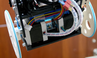
크기와 무게의 최적화를 설계 목표로 설정 한 것을 다른 역학에 대해 말을 많이가 아니다. 프로토 타입 몸은 4mm 합판의 일부 조각의 내장 및 에폭시와 함께 붙어있다.
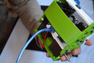
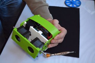
로봇의 일반보기
소프트웨어 플랫폼
현재 자원과 ESP8266에 소프트웨어를 개발하기위한 지원의 재산이있다. 제조업체 Espressif하는 RTOS없이 운영 체제와 다른 하나 하나가 제공하는 두 개의 SDK가 있습니다. 도있다 아두 이노 코어 의 심바 크로스 플랫폼 RTOS 프레임 워크와 MicroPython은 . 새로운 언어와 프레임 워크가 큰 인 지금 가끔씩 튀어 나올 것 같다!
이 로봇에 대한 몇 가지 프로토 타입을 사용하여 아두 이노 코어에서 수행 된 PlatformIO를 빌드 시스템으로. 프로토 타입 작업은에서 찾을 수 있습니다 해당 지점 GitHub의의 REPO의.
그러나 최대의 유연성과 제어를 위해, 나는 제조업체의 “비 OS”SDK로 전환. 하나는이 마이크로 컨트롤러와 함께 얻을 수있는 즉 약으로 기본입니다. 나는 특히,이 SDK에 사용할 멋진 도서관이 있었다 찾을 수 기쁘게 생각 libesphttpd 간단한 HTTP 서버와 파일 시스템을 구현한다. 그것은 또한 웹 소켓 통신 시설을 갖추고으로이 프로젝트를위한 안성맞춤이었다.
모바일 웹 UI
로봇에 전원을 공급하고, WiFi 액세스 포인트에 클라이언트 장치를 연결 한 후, 하나는 기본 IP 주소에서 웹 브라우저 사용자 인터페이스를 열 수 있습니다 192.168.4.1.
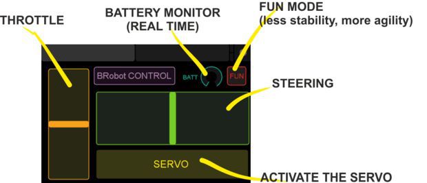
나는 가능한 한 간단하게 UI를 유지하기 위해 노력했다. 그것은 본질적으로 HTML5 캔버스에 그려진 가상 “조이스틱”로 구성되어 있습니다. 터치 디바이스에서 휴대 전화 등, 꽤 직관적 인 느낌.
조정에 사용되는 사용자 인터페이스.
의 URL에서 로봇의 PID 매개 변수의 온라인 튜닝을위한 UI도 있습니다 /pid. 그것은 진행중인 작품이지만, 반 사용 가능한 상태에서 이미. 그것은 본질적으로 펌웨어를 매개 변수가 변경 될 때마다 다시 깜박하지 않고 한 번에 로봇을 조정 할 수 있습니다. 하나는 UI를 통해 플래시 메모리에 조정 매개 변수를 저장할 수 있습니다.
초기 PID 튜닝 사용자 인터페이스를 제공합니다.
웹 소켓을 통해 대기 시간이 짧은 통신
아마이 프로젝트의 가장 흥미로운 부분은 낮은 지연 시간 원격 제어를 달성하는 방법이다.
전통적으로 사람들은 ESP8266에 HTTP API가 어떤 종류의를 구현하고있다. 그것은 각 명령에 대해 별도의 URL가 있다는 것을 의미한다. 예는 로봇 차, 같은 URL이있을 것 /forward, /backward, /stop, /turn-left, /turn-right등 다음 만들 것 클라이언트 응용 프로그램 AJAX의 로봇을 제어하는 요청을. 그러나, TCP 연결을 열고 모든 명령에 구문 분석 HTTP 헤더가있을 것입니다 의미합니다. 즉, 불필요한 오버 헤드 및 지연을 도입한다. 이 컨트롤은 그런 식으로 매우 부드러운 없을 것이다.
더 나은 대안은 열려있는 TCP 소켓을 유지하고 두 방향으로 그것을 통해 정보를 전송하는 것입니다. ESP8266 원시 TCP 통신을위한 일류 지원을하고 있지만, 자바 스크립트 하나는 원시 TCP 소켓을 열 수 없습니다. 대신있다 WebSockets를 정의 된 핸드 쉐이킹 프로토콜 및 데이터 프레임 포맷 첨가 TCP 소켓이다. 때문에 libesphttpd웹 소켓 구현을 가지고, 나는이 세부 사항에 대해 걱정하지 않았지만, 단지 데이터 패킷을 교환한다.
데이터 패킷의 첫 번째 바이트에 해당되는 명령을 표시하고, 이후의 추가 바이트 데이터이다 : 거기 로봇와 UI 사이에 통신하는 매우 단순한 프로토콜이다. 부가 데이터의 길이는 각각의 명령에 대한 알려진 고정된다. 예를 들어, 클라이언트에 의해 전송 된 “스티어링”데이터 패킷은 3 바이트로 구성 첫 번째 바이트 (즉, 같은 코드로 정의되어 제로 STEERING). 두번째 바이트는 원하는 속도를 나타내고, 세 번째는 회전 속도를 나타내는 (네거티브 = 좌, 포지티브 = 우측). 이 경우, 두 번째 및 세 번째 바이트는 8 비트 부호있는 정수로 해석된다. 데이터 바이트의 해석은 문제의 명령에 따라 달라집니다.
부드러운 양방향 통신을 감안할 때, 하나는 멋진 모든 종류의 것들을 구현할 수 있습니다. 예를 들어, 로봇은 클라이언트 웹 응용 프로그램에서 배터리 모니터링을 허용, 연결된 모든 클라이언트에 현재 배터리 독서를 보낼 수 있습니다. 또한, 가장 실용적인 것들 중 하나는 PID 컨트롤러 매개 변수의 온라인 튜닝이다.
데이터 바이트의 C 코드, 조작 및 천연 재 해석된다. 자바 스크립트에서는, 이진 데이터는로 표현되는 ArrayBuffer원시 이진 데이터의 블록의 표현은 본질적이다. 액세스 및 수정하려면, 하나는 사용할 수 있습니다 DataView기본 바이너리 버퍼에 바이트 수준의 액세스를 제공한다. 하나는 예를 들어 “바이트의 16 비트 부호없는 정수 (리틀 엔디안)로 13 쓰기 버퍼의 처음부터 오프셋 2″라고 할 수있다. 나는 자바 스크립트 API를 제공 낮은 수준의 제어가 찾을 수 놀랐다.
고정 소수점 센서 퓨전
I2C를 통해 MPU6050와 통신하는 것은 쉽다. 하나는 1 kHz에서 업데이트되는 세 축의 가속도와 자이로 측정치를 포함하는 하드웨어 레지스터를 판독 할 수있다. 배향으로이 값을 변환하는 과정은 “센서 퓨전”라고한다. 거기를 수행하는데 사용될 수 센서 자체로 신호 처리 코어이고,이 우수한 I2Cdevlib것을 구현한다. 그러나, 내가하고 싶지 않은 무언가 센서에 바이너리 펌웨어 덩어리를 업로드해야합니다. 또한, 그 알고리즘은 미가공 데이터는 1 kHz에서 사용할 경우에도 200 Hz의 샘플링 레이트만을 할 수있다.
주어진 ESP8266가 가진 32 비트 코어를 가지고 16 * 16 -> 32 비트 곱셈 확대, I 센서 융합하는 대신에 구현 될 수 있다고 생각. 가장 특히, 선택할 수있는 많은 알고리즘이 있습니다 보완 필터 , 칼만 필터 와 Madgwick 필터 . 후자는 독창적으로 작동 최첨단 신규 알고리즘 쿼터니온 방향의 표현. 또한이 시작하는 데 사용할 수 몇 가지 예제 코드이었다, 그래서 Madgwick 알고리즘이 선택되었다.
ESP8266는 부동 소수점 유닛이 골대를 벗어났습니다하고, 부동 소수점 연산은 소프트웨어로 구현해야합니다. 즉, 복잡한 비즈니스 컴파일러 지원 라이브러리에서 수행되었지만, 그것은 아주 느리다. 따라서, 나는 완전히 알고리즘의 부동 소수점 숫자의 사용을 방지하기 위해 원했다. 따라서 나는 Q16.16에 샘플 코드를 번역하기로 결정했습니다 고정 소수점 숫자 표현을 . 고정 점은 우리가 기본적으로 정수를 위해 노력하고 있지만, 16 최하위 바이트가 소수 부분으로 촬영 한 것을 의미한다.
구현에 대한 하나 개의 좋은 실용적인 세부 다음 Madgwick 알고리즘에, 하나는 어떤 경우에 벡터와 사원 수를 정상화해야한다. 이 경우 정규화는 제곱근으로 나눈 것을 의미한다. ESP8266의 핵심은 하드웨어 부문을 가지고 있지 않기 때문에이 소프트웨어에서 구현 될 필요가 있습니다. 동일은 제곱근에 적용됩니다. 우리는 어떻게 든 그것을 피할 수있는 경우에 따라서는 개별적으로 두 작업을 수행하는 것이 훨씬 이해가되지 않습니다. 반면에, 곱셈 연산의 측면에서 상대적으로 저렴합니다. 제곱근 나누면 제곱근의 역수를 곱한 것과 같다. 즉 여기에서 이루어졌다 무슨 – 상호 제곱근 함수의 라인을 따라 구현 이 StackOverflow의 대답 .
캐스케이드 PID 제어
어떻게 로봇이 실제로 균형을 유지합니까? 지금까지 우리는 로봇의 방향의 좋은 평가가 있습니다. 어떻게 든 적합한 모터 출력 신호로 변환되어야한다.
대답 할 두 가지 질문이 있습니다 :
로봇의 기울기 각도는 균형을 유지하기 위해 무엇을해야 하는가?
어떤 모터 출력 전력은 소정 경사각을 달성해야 하는가?
캐스 캐 이드 :이 자연스럽게 종종 자기 밸런싱 로봇에 구현 된 제어 전략에 이르게 PID 컨트롤러 . PID 제어에 대한 소개, 나는 기사 추천 박사 학위없이 PID를 팀 웨스콧에 의해. 본질적으로, 제 제어부는 입력으로서 원하는 속도를 취득하는 속도를 달성하기 위해 경사 각도를 제어한다. 바람직한 경사각은 그 각도를 달성하기 위해 모터 출력을 조정하는 제 제어기에 공급된다.
물론, 상기 제 2 제어부는 MPU6050 관성 측정 유닛을 통해 피드백을 얻는다. 한편, 현재 속도의 피드백을 얻는 것은 사소한 일이 아니다. 하나는 모터 샤프트에 회전 인코더를 설치하여 그것을 달성 할 수있다. 비용을 최소화하고 회로를 단순화하기 위해, 나는 그것을 밖으로 떠났다. 대신에, 내 코드에 사용되는 조 근사있다 : 속도 피드백이 단기 변동을 취소하기 위해 평활화 모터 구동 신호로부터 취해진 다. 이 사실은 놀라 울 정도로 잘 작동합니다!
또한, 단순한 형태의 게인 스케줄링은 로봇이 낙하하려고하는 상황에서 사용된다. 높은 비례 이득 PID 계수들의 상이한 세트는 다시 안정성을 달성하기 위해로드된다. 아래의 비디오 (일부 fallovers와 함께) 당신은 행동에서 볼 수 있습니다.
여기에 설명 된 제어 방식은 자기 밸런싱 로봇을 구현하는 유일한 방법은 아니다. 참고 이 문서 로봇의 동적 모델을 기반으로 제어 방식과 비교합니다.
소프트웨어 드라이버
마지막으로을의이 ESP8266 프로그래밍의 일부 실용성을 논의하자.
이 마이크로 컨트롤러에 하나의 문제는 하드웨어 주변의 부족이다. 특히, 칩상의 I2C 또는 PWM 어떠한 하드웨어 구현은 없다. 그들은 소프트웨어로 구현되어야한다. 문제는 매우 동일한 프로세서 코어 끊임없이 무선 통신을 처리하는 것으로한다. 그래서, 다른 소프트웨어 루틴은 와이파이 인터럽트에 의해 중단 얻을 수 있습니다. I2C 및 PWM 모두 타이밍에 대한 중요하기 때문에 그것은 약간의 문제입니다.
PWM 및 I2C의 소프트웨어 구현은 Espressif SDK와 함께 번들로 제공됩니다. 그러나 글을 쓰는, 그들은 어떤 식 으로든하거나 비효율적에 결함이 있습니다. 다행히, 지역 사회에서 어떤 똑똑한 사람들은 자신의 드라이버를 출시했다. I 사용하여 결국 ESP8266_new_pwm정확한 타이밍 안정된 PWM 신호를 실현할 NMI 인터럽트를 사용 스테판 브루엔스 의해. 모터는 2 kHz에서 PWM으로 공급된다.
I2C를 들어,라는 빠른 조립 구현 brzo_i2c파스칼 커턴스키으로 사용 하였다. 나는 I2C 거래 중에 완전히 비활성화 인터럽트 때문에 처음에는 I2C 드라이버에 약간의 문제가 있었다. 이는 결국 일부 WiFi를 발사 할 수없는 방해 아마도에, 펌웨어 충돌로했다. 즉, 쉽게 인터럽트를 비활성화 명령을 주석에 의해 수정되었습니다. 즉, I2C 타이밍을 타협하지만, 실제로는 모든 것이 매우 잘 작동하고있다.
피드백
이 문서에서 설명하는 무언가의 더 정교한 설명을 좋아하거나 해결하기 위해 발견 뭔가를했을 경우,이 사이트에 문제를 제기하십시오 GitHub의의의 repo . 당신은 또한에 연락처 찾을 수 있습니다 이 페이지를 . 모든 의견은 매우 환영하고 감사합니다.
Ever since I started tinkering with Arduino and embedded systems, I’ve been pretty excited about building a self-balancing, Segway-like robot. There’s a wealth of similar projects and resources around the Internet.
The first prototype was built inside a plastic lunch box. It used an Arduino Nano and infrared remote control. It used the MPU6050 inertial measurement unit for detecting the orientation of the robot. The balancing worked very well, but the infrared remote control was quite impractical and unreliable.
The project was revived when I learned about ESP8266, a cheap, WiFi enabled microcontroller with a pretty powerful core. Having some background in web development, the WiFi connectivity looked like a world of possibilities to me.
Traditionally in the Arduino community, remote controlled robots have been implemented using Bluetooth for the communication. However, this practically means that the controller software has to be implemented separately on each platform (Android, iOS, PC, etc.)
Web applications implemented with HTML and JavaScript are becoming more and more popular. One of the reasons is the portability. When the web app has been written once, it can be run on any platform which has a good enough web browser.
The ESP8266 can be configured as a WiFi access point. One can set up a HTTP server serving static pages, making the ESP8266 able to serve web apps. Now imagine if the robot control software was implemented as a web application! That is the key idea behind my project ESPway.
The code and schematics for this little robot can be found on GitHub. There are preliminary instructions on building, developing and using the software. I’m also building some kind of a user manual there. The project was also discussed on Reddit a while ago when I posted the video.
Safety first
Before diving deeper in the technical details, I though I should warn you about safety in case you are going to build this yourself.
The electronics and software don’t contain any safety features (except low voltage cutoff) as of writing this. If the firmware on the ESP8266 crashes / stalls (it can and probably will happen), there’s nothing stopping the motors from spinning. This is not a particular issue in my case where the robot is small and light enough to not damage its surroundings. However, please consider the safety before building a larger and heavier version of this robot. One could probably implement some failsafe system which would shut off the motors in case of a software failure.
Electronics and mechanics
Most of the parts for this robot are sourced from eBay or AliExpress. The complete schematic can be found on GitHub. One of the goals of this project was to keep the electronics as simple and cheap as possible.
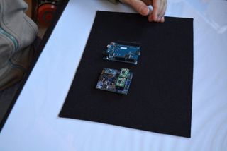
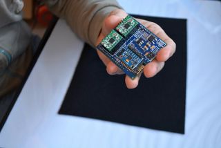
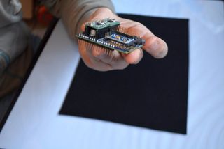
At the core of the robot there is the ESP8266 microcontroller. It is not used as a standalone component but there’s a WEMOS D1 mini board. It has a USB connector and a USB-to-UART converter for uploading the firmware.
The MPU6050 is used as the orientation sensor. It communicates via I2C, and there’s a plenty of affordable breakout boards available. I used one called GY-521.
The motors are plain old DC motors with an integrated metal gearbox. The nominal revolution rate is 300 rpm, and they are rated for 6V. One can find these motors by searching for “n20 300rpm” or “12ga 300rpm”.
The motors are driven by the L293D dual H-bridge motor driver IC. This IC was chosen mostly because that’s what I had at hand when building the robot. Now I’ve learned that the bipolar transistor outputs produce a significant voltage drop across the bridge. Eventually I’ll replace the driver with a DRV8833 which has MOSFET outputs.
I’m using a 2-cell LiPo battery for powering the robot. It gives ~8.4 volts when fully charged. The battery voltage is monitored via the analog input of the ESP8266, and there’s an optional feature to cut off the motors when the battery voltage falls under a certain threshold. That’s common practice used with LiPo batteries. The analog input range is 0-1 volts. On the D1 mini board, there already is a voltage divider with a ratio of 1:3.3. Hence I only had to add one resistor to modify the ratio to 1:10, which scales the battery voltage to fit the analog input range.
Finally, two WS2812B NeoPixels are added as the “eyes” of the robot. They have proven quite useful for reporting the current state of the robot (if it has fallen, if there’s OTA update in progress etc.)
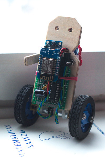
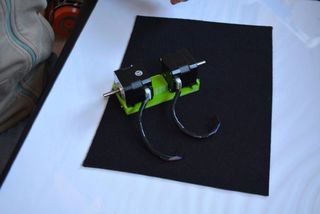
There’s not much to say about the mechanics, other that that optimization of size and weight were set as design goals. The prototype body was built out of some pieces of 4mm plywood and glued together with epoxy.
A general view of the robot
Software platform
Nowadays there is a wealth of resources and support for developing software on the ESP8266. There are two SDKs offered by the manufacturer Espressif, one with a RTOS and the other one with no operating system. There is also an Arduino core, the Simba cross-platform RTOS framework and MicroPython. New languages and frameworks seem to pop out every now and then, which is great!
Some prototyping for this robot was done on the Arduino core, using PlatformIO as the build system. The prototyping work can be found in the corresponding branch of the GitHub repo.
However, for maximum flexibility and control, I switched to the manufacturer’s “non-OS” SDK. That is about as native as one can get with this microcontroller. I was pleased to find there were some great libraries available for this SDK, particularly libesphttpd which implements a simple HTTP server and a filesystem. It was a great fit for this project as it also features WebSocket communication facilities.
Mobile web UI
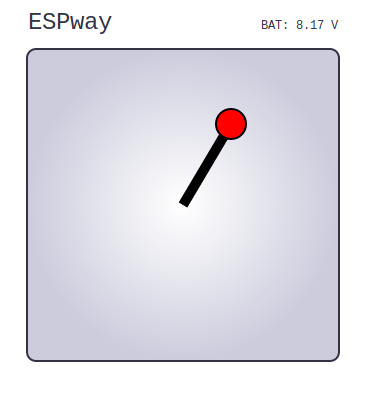
After powering on the robot and connecting a client device to the WiFi access point, one can open the user interface with a web browser at the default IP address 192.168.4.1.
I tried to keep the UI as simple as possible. It essentially consists of a virtual “joystick” drawn on a HTML5 canvas. On a touch device such as a mobile phone, it feels quite intuitive.
The user interface used for steering.
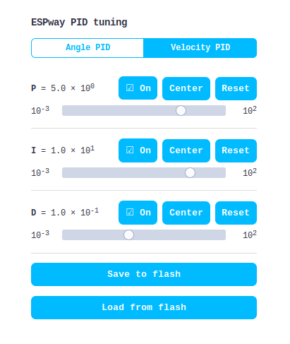
There is also a UI for on-line tuning of the robot’s PID parameters at the url /pid. It is a work in progress, but it’s already in a semi-usable state. It essentially allows tuning the robot in one pass without re-flashing the firmware every time the parameters are changed. One can save the tuned parameters to the flash memory via the UI.
The initial PID tuning user interface.
Low latency communications via a WebSocket
Probably the most interesting part of this project is the method of achieving low latency remote control.
Traditionally people have been implementing some kind of HTTP APIs on the ESP8266. It means that there’s a separate URL for each command. E.g. for a robot car, there would be URLs like /forward, /backward, /stop, /turn-left, /turn-right etc. The client application would then make AJAX requests to control the robot. However, that means there would be a TCP connection opened and a HTTP header parsed on every command. That introduces unnecessary overhead and latency. The control would not be very smooth that way.
A better alternative is to keep the TCP socket open and send information over it in two directions. While the ESP8266 has first-class support for raw TCP communication, in JavaScript one can’t open raw TCP sockets. Instead there are WebSockets which are TCP sockets added with a defined handshaking protocol and a data frame format. Because libesphttpd has a WebSocket implementation, I didn’t have to care about these details but just exchange data packets.
There’s a very simple protocol in the communication between the robot and the UI: the first byte of a data packet indicates which command is in question, and the subsequent bytes are additional data. The length of the additional data is known and fixed for each command. For example, a “steering” data packet sent by the client consists of three bytes: the first byte is zero (that’s defined in the code as STEERING). The second byte indicates the desired speed and the third one indicates turning rate (negative = left, positive = right). In this case the second and third byte are interpreted as 8-bit signed integers. The interpretation of the data bytes depends on the command in question.
Given smooth two-way communication, one can implement all kinds of cool things. For example, the robot can send the current battery reading to all connected clients, allowing battery monitoring in the client web app. Also, one of the most practical things is on-line tuning of the PID controller parameters.
In the C code, manipulation and reinterpretation of the data bytes is natural. In JavaScript, binary data is represented as an ArrayBuffer which is essentially a representation of a block of raw binary data. To access and modify it, one can use a DataView, which gives byte level access to the underlying binary buffer. One can e.g. say “write 13 as a 16-bit unsigned integer (little Endian) at byte offset 2 from the beginning of the buffer”. I was actually surprised to find there is such low level control available in the JavaScript APIs.
Fixed-point sensor fusion
Communicating with the MPU6050 via I2C is easy. One can read the hardware registers which contain acceleration and gyro readings on three axes that are updated at 1 kHz. The process of translating these values into an orientation is called “sensor fusion”. There is a signal processing core in the sensor itself that could be used to do that, and the excellent I2Cdevlib implements that. However, that requires uploading a binary firmware blob on the sensor, which is something I did not want to do. In addition, that algorithm is only capable of 200 Hz sample rate even though the raw data is available at 1 kHz.
Given that the ESP8266 has a 32-bit core with 16*16 -> 32-bit widening multiplication, I thought the sensor fusion could be implemented on that instead. There are many algorithms to choose from, most notably the complementary filter, Kalman filter and Madgwick filter. The latter is a state-of-the-art novel algorithm which works cleverly with the quaternion representation of the orientation. Additionally there was some sample code available to get started with, so the Madgwick algorithm was chosen.
The ESP8266 misses a floating point unit, and the floating point operations must be implemented in software. That complex business has been done in the compiler support libraries, but it is quite slow. Hence, I wanted to entirely avoid the usage of floating point numbers in the algorithm. Therefore I chose to translate the sample code to the Q16.16 fixed point number representation. Fixed point means that we’re essentially working integers but the 16 least significant bytes are taken to be the fractional part.
One nice practical detail about the implementation: in the Madgwick algorithm, one has to normalize vectors and quaternions on some occasions. Normalization in this case means dividing by a square root. ESP8266’s core doesn’t have hardware division, so it has to be implemented in the software. The same applies for the square root. Thus it doesn’t make much sense to do both operations individually if we could avoid it somehow. On the other hand, multiplication is relatively cheap in terms of operations. Dividing by the square root is equivalent to multiplying by the reciprocal of the square root. That’s what was done here – a reciprocal square root function was implemented along the lines of this StackOverflow answer.
Cascade PID control
How does the robot actually maintain the balance? So far we have a nice estimate of the orientation of the robot. It has to be somehow translated to a suitable motor output signal.
There are two questions to answer:
What should the tilt angle of the robot be in order to stay balanced?
What should the motor output power be to achieve the desired tilt angle?
This naturally leads to a control strategy that is often implemented in self-balancing robots: a cascaded PID controller. For an introduction on PID control, I recommend the article PID without a PhD by Tim Wescott. Essentially, the first controller gets the desired velocity as an input and controls the inclination angle to achieve that velocity. The desired inclination angle is fed to a second controller which regulates the motor output power to achieve that angle.
Naturally, the second controller gets feedback via the MPU6050 inertial measurement unit. On the other hand, getting feedback of the current velocity is not a trivial task. One could achieve that by installing rotation encoders on the motor shafts. In order to minimize the cost and simplify the circuitry, I left that out. Instead, there’s a crude approximation used in my code: the velocity feedback is taken from the motor drive signal which is smoothed in order to cancel short-term variations. This actually works surprisingly well!
In addition, a simple form of gain scheduling is used in situations where the robot is about to fall. A different set of PID coefficients with higher proportional gain is loaded in order to reach stability again. You can see this in action (along with some fallovers 😉 in the video below.
The control scheme described here is not the only way to implement self-balancing robots. See this articlefor comparison with a control scheme based on a dynamic model of the robot.
Software drivers
Last but not least, let’s discuss some practicalities of programming the ESP8266.
One problem with this microcontroller is the lack of hardware peripherals. In particular, there are no hardware implementations of I2C or PWM on the chip. They have to be implemented in software. The problem is that the very same processor core has constantly handle the WiFi communication. So, any other software routine might get interrupted by the WiFi interrupts. That’s a bit of a problem since both I2C and PWM are critical about timing.
Software implementations of PWM and I2C are bundled with the Espressif SDK. However, as of writing, they are flawed in some way or just inefficient. Luckily, some smart people in the community have rolled their own drivers. I ended up using ESP8266_new_pwm by Stefan Bruens, which uses NMI interrupts to realize a stable PWM signal with correct timing. The motors are fed with 2 kHz PWM.
For I2C, a fast assembly implementation called brzo_i2c by Pascal Kurtansky was used. I had some problems with the I2C driver at first since it completely disabled interrupts during I2C transactions. That eventually led to the firmware crashing, probably due to some WiFi interrupt not being able to fire. That was easily fixed by commenting out the instruction that disabled the interrupts. That compromises the I2C timing, but in practice everything has been working very well.
Feedback
If you would like a more elaborate description of something described in this article or have found something to fix, please file an issue on this site’s GitHub repo. You can also find contact details on this page. Any feedback is very welcome and appreciated.


 JJROBOTS Science&fun 2015