Ever since I started tinkering with Arduino and embedded systems, I’ve been pretty excited about building a self-balancing, Segway-like robot. There’s a wealth of similar projects and resources around the Internet.
The first prototype was built inside a plastic lunch box. It used an Arduino Nano and infrared remote control. It used the MPU6050 inertial measurement unit for detecting the orientation of the robot. The balancing worked very well, but the infrared remote control was quite impractical and unreliable.
The project was revived when I learned about ESP8266, a cheap, WiFi enabled microcontroller with a pretty powerful core. Having some background in web development, the WiFi connectivity looked like a world of possibilities to me.
Traditionally in the Arduino community, remote controlled robots have been implemented using Bluetooth for the communication. However, this practically means that the controller software has to be implemented separately on each platform (Android, iOS, PC, etc.)
Web applications implemented with HTML and JavaScript are becoming more and more popular. One of the reasons is the portability. When the web app has been written once, it can be run on any platform which has a good enough web browser.
The ESP8266 can be configured as a WiFi access point. One can set up a HTTP server serving static pages, making the ESP8266 able to serve web apps. Now imagine if the robot control software was implemented as a web application! That is the key idea behind my project ESPway.
The code and schematics for this little robot can be found on GitHub. There are preliminary instructions on building, developing and using the software. I’m also building some kind of a user manual there. The project was also discussed on Reddit a while ago when I posted the video.
Safety first
Before diving deeper in the technical details, I though I should warn you about safety in case you are going to build this yourself.
The electronics and software don’t contain any safety features (except low voltage cutoff) as of writing this. If the firmware on the ESP8266 crashes / stalls (it can and probably will happen), there’s nothing stopping the motors from spinning. This is not a particular issue in my case where the robot is small and light enough to not damage its surroundings. However, please consider the safety before building a larger and heavier version of this robot. One could probably implement some failsafe system which would shut off the motors in case of a software failure.
Electronics and mechanics
Most of the parts for this robot are sourced from eBay or AliExpress. The complete schematic can be found on GitHub. One of the goals of this project was to keep the electronics as simple and cheap as possible.
At the core of the robot there is the ESP8266 microcontroller. It is not used as a standalone component but there’s a WEMOS D1 mini board. It has a USB connector and a USB-to-UART converter for uploading the firmware.
The MPU6050 is used as the orientation sensor. It communicates via I2C, and there’s a plenty of affordable breakout boards available. I used one called GY-521.
The motors are plain old DC motors with an integrated metal gearbox. The nominal revolution rate is 300 rpm, and they are rated for 6V. One can find these motors by searching for “n20 300rpm” or “12ga 300rpm”.
The motors are driven by the L293D dual H-bridge motor driver IC. This IC was chosen mostly because that’s what I had at hand when building the robot. Now I’ve learned that the bipolar transistor outputs produce a significant voltage drop across the bridge. Eventually I’ll replace the driver with a DRV8833 which has MOSFET outputs.
I’m using a 2-cell LiPo battery for powering the robot. It gives ~8.4 volts when fully charged. The battery voltage is monitored via the analog input of the ESP8266, and there’s an optional feature to cut off the motors when the battery voltage falls under a certain threshold. That’s common practice used with LiPo batteries. The analog input range is 0-1 volts. On the D1 mini board, there already is a voltage divider with a ratio of 1:3.3. Hence I only had to add one resistor to modify the ratio to 1:10, which scales the battery voltage to fit the analog input range.
Finally, two WS2812B NeoPixels are added as the “eyes” of the robot. They have proven quite useful for reporting the current state of the robot (if it has fallen, if there’s OTA update in progress etc.)
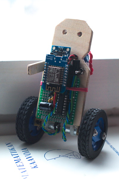
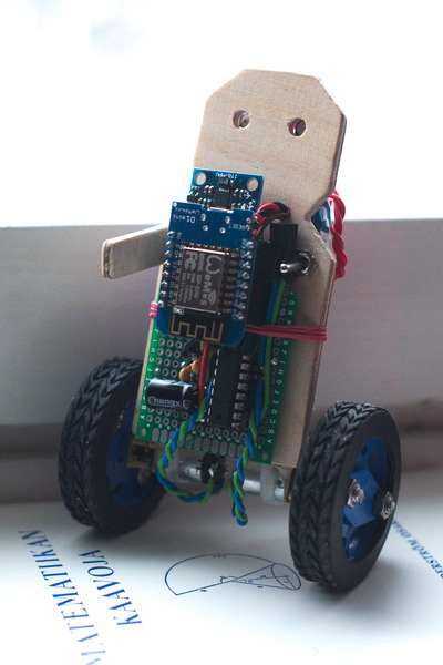
There’s not much to say about the mechanics, other that that optimization of size and weight were set as design goals. The prototype body was built out of some pieces of 4mm plywood and glued together with epoxy.
A general view of the robot
Software platform
Nowadays there is a wealth of resources and support for developing software on the ESP8266. There are two SDKs offered by the manufacturer Espressif, one with a RTOS and the other one with no operating system. There is also an Arduino core, the Simba cross-platform RTOS framework and MicroPython. New languages and frameworks seem to pop out every now and then, which is great!
Some prototyping for this robot was done on the Arduino core, using PlatformIO as the build system. The prototyping work can be found in the corresponding branch of the GitHub repo.
However, for maximum flexibility and control, I switched to the manufacturer’s “non-OS” SDK. That is about as native as one can get with this microcontroller. I was pleased to find there were some great libraries available for this SDK, particularly libesphttpd which implements a simple HTTP server and a filesystem. It was a great fit for this project as it also features WebSocket communication facilities.
Mobile web UI
After powering on the robot and connecting a client device to the WiFi access point, one can open the user interface with a web browser at the default IP address 192.168.4.1.
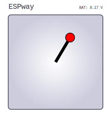
I tried to keep the UI as simple as possible. It essentially consists of a virtual “joystick” drawn on a HTML5 canvas. On a touch device such as a mobile phone, it feels quite intuitive.
The user interface used for steering.
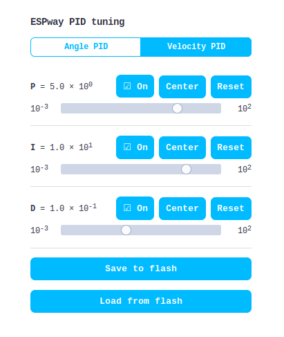
There is also a UI for on-line tuning of the robot’s PID parameters at the url /pid. It is a work in progress, but it’s already in a semi-usable state. It essentially allows tuning the robot in one pass without re-flashing the firmware every time the parameters are changed. One can save the tuned parameters to the flash memory via the UI.
The initial PID tuning user interface.
Low latency communications via a WebSocket
Probably the most interesting part of this project is the method of achieving low latency remote control.
Traditionally people have been implementing some kind of HTTP APIs on the ESP8266. It means that there’s a separate URL for each command. E.g. for a robot car, there would be URLs like /forward, /backward, /stop, /turn-left, /turn-right etc. The client application would then make AJAX requests to control the robot. However, that means there would be a TCP connection opened and a HTTP header parsed on every command. That introduces unnecessary overhead and latency. The control would not be very smooth that way.
A better alternative is to keep the TCP socket open and send information over it in two directions. While the ESP8266 has first-class support for raw TCP communication, in JavaScript one can’t open raw TCP sockets. Instead there are WebSockets which are TCP sockets added with a defined handshaking protocol and a data frame format. Because libesphttpd has a WebSocket implementation, I didn’t have to care about these details but just exchange data packets.
There’s a very simple protocol in the communication between the robot and the UI: the first byte of a data packet indicates which command is in question, and the subsequent bytes are additional data. The length of the additional data is known and fixed for each command. For example, a “steering” data packet sent by the client consists of three bytes: the first byte is zero (that’s defined in the code as STEERING). The second byte indicates the desired speed and the third one indicates turning rate (negative = left, positive = right). In this case the second and third byte are interpreted as 8-bit signed integers. The interpretation of the data bytes depends on the command in question.
Given smooth two-way communication, one can implement all kinds of cool things. For example, the robot can send the current battery reading to all connected clients, allowing battery monitoring in the client web app. Also, one of the most practical things is on-line tuning of the PID controller parameters.
In the C code, manipulation and reinterpretation of the data bytes is natural. In JavaScript, binary data is represented as an ArrayBuffer which is essentially a representation of a block of raw binary data. To access and modify it, one can use a DataView, which gives byte level access to the underlying binary buffer. One can e.g. say “write 13 as a 16-bit unsigned integer (little Endian) at byte offset 2 from the beginning of the buffer”. I was actually surprised to find there is such low level control available in the JavaScript APIs.
Fixed-point sensor fusion
Communicating with the MPU6050 via I2C is easy. One can read the hardware registers which contain acceleration and gyro readings on three axes that are updated at 1 kHz. The process of translating these values into an orientation is called “sensor fusion”. There is a signal processing core in the sensor itself that could be used to do that, and the excellent I2Cdevlib implements that. However, that requires uploading a binary firmware blob on the sensor, which is something I did not want to do. In addition, that algorithm is only capable of 200 Hz sample rate even though the raw data is available at 1 kHz.
Given that the ESP8266 has a 32-bit core with 16*16 -> 32-bit widening multiplication, I thought the sensor fusion could be implemented on that instead. There are many algorithms to choose from, most notably the complementary filter, Kalman filter and Madgwick filter. The latter is a state-of-the-art novel algorithm which works cleverly with the quaternion representation of the orientation. Additionally there was some sample code available to get started with, so the Madgwick algorithm was chosen.
The ESP8266 misses a floating point unit, and the floating point operations must be implemented in software. That complex business has been done in the compiler support libraries, but it is quite slow. Hence, I wanted to entirely avoid the usage of floating point numbers in the algorithm. Therefore I chose to translate the sample code to the Q16.16 fixed point number representation. Fixed point means that we’re essentially working integers but the 16 least significant bytes are taken to be the fractional part.
One nice practical detail about the implementation: in the Madgwick algorithm, one has to normalize vectors and quaternions on some occasions. Normalization in this case means dividing by a square root. ESP8266’s core doesn’t have hardware division, so it has to be implemented in the software. The same applies for the square root. Thus it doesn’t make much sense to do both operations individually if we could avoid it somehow. On the other hand, multiplication is relatively cheap in terms of operations. Dividing by the square root is equivalent to multiplying by the reciprocal of the square root. That’s what was done here – a reciprocal square root function was implemented along the lines of this StackOverflow answer.
Cascade PID control
How does the robot actually maintain the balance? So far we have a nice estimate of the orientation of the robot. It has to be somehow translated to a suitable motor output signal.
There are two questions to answer:
- What should the tilt angle of the robot be in order to stay balanced?
- What should the motor output power be to achieve the desired tilt angle?
This naturally leads to a control strategy that is often implemented in self-balancing robots: a cascaded PID controller. For an introduction on PID control, I recommend the article PID without a PhD by Tim Wescott. Essentially, the first controller gets the desired velocity as an input and controls the inclination angle to achieve that velocity. The desired inclination angle is fed to a second controller which regulates the motor output power to achieve that angle.
Naturally, the second controller gets feedback via the MPU6050 inertial measurement unit. On the other hand, getting feedback of the current velocity is not a trivial task. One could achieve that by installing rotation encoders on the motor shafts. In order to minimize the cost and simplify the circuitry, I left that out. Instead, there’s a crude approximation used in my code: the velocity feedback is taken from the motor drive signal which is smoothed in order to cancel short-term variations. This actually works surprisingly well!
In addition, a simple form of gain scheduling is used in situations where the robot is about to fall. A different set of PID coefficients with higher proportional gain is loaded in order to reach stability again. You can see this in action (along with some fallovers 😉 in the video below.
The control scheme described here is not the only way to implement self-balancing robots. See this articlefor comparison with a control scheme based on a dynamic model of the robot.
Software drivers
Last but not least, let’s discuss some practicalities of programming the ESP8266.
One problem with this microcontroller is the lack of hardware peripherals. In particular, there are no hardware implementations of I2C or PWM on the chip. They have to be implemented in software. The problem is that the very same processor core has constantly handle the WiFi communication. So, any other software routine might get interrupted by the WiFi interrupts. That’s a bit of a problem since both I2C and PWM are critical about timing.
Software implementations of PWM and I2C are bundled with the Espressif SDK. However, as of writing, they are flawed in some way or just inefficient. Luckily, some smart people in the community have rolled their own drivers. I ended up using ESP8266_new_pwm by Stefan Bruens, which uses NMI interrupts to realize a stable PWM signal with correct timing. The motors are fed with 2 kHz PWM.
For I2C, a fast assembly implementation called brzo_i2c by Pascal Kurtansky was used. I had some problems with the I2C driver at first since it completely disabled interrupts during I2C transactions. That eventually led to the firmware crashing, probably due to some WiFi interrupt not being able to fire. That was easily fixed by commenting out the instruction that disabled the interrupts. That compromises the I2C timing, but in practice everything has been working very well.


