Hello, everyone!
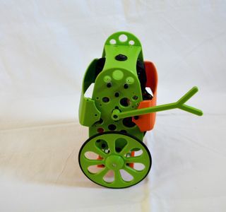
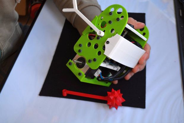
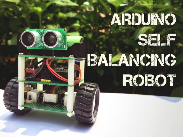
In this instructable, I’ll show you how to build a small self-balancing robot that can move around avoiding obstacles. This is a tiny robot measuring 4 inches wide and 4 inches tall and is based on the Arduino Pro Mini development board and the MPU6050 accelerometer-gyroscope module.
In the steps that follow, we will see how to interface the MPU6050 with Arduino, how to measure the angle of inclination of the robot, how to use PID to make the robot stay balanced. An ultrasonic rangefinder is also added to the robot which prevents it from banging into obstacles as it wanders around.
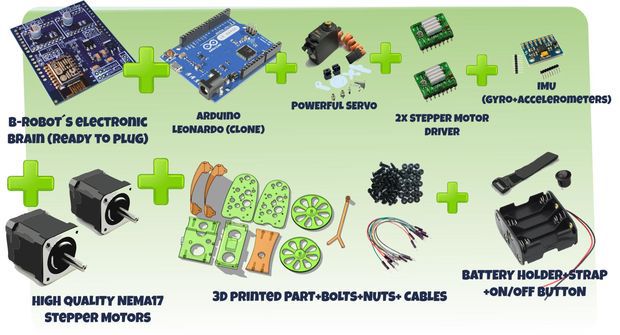
Parts List
I bought most of these parts from aliexpress but you can find them in any other electronics store as well.
1. Arduino Pro Mini
2. GY-521 module with MPU-6050
3. DRV8833 Pololu motor driver
4. 2, 5V boost converter
5. US-020 ultrasonic distance sensor
6. NCR18650 battery and holder
7. Pair of micro metal gear motors (N20, 6V, 200 rpm) and brackets
8. Pair of 42x19mm wheels
9. 3, Double-sided prototype PCB (4cm x 6cm)
10. 8, 25cm Nylon spacers and 4, nylon nuts
Apart from the above, you will need some cables, berg connectors and one on/off switch.
Step 1: A Bit of Theory
Let’s start with some fundamentals before getting our hands dirty.
The self-balancing robot is similar to an upside down pendulum. Unlike a normal pendulum which keeps on swinging once given a nudge, this inverted pendulum cannot stay balanced on its own. It will simply fall over. Then how do we balance it? Consider balancing a broomstick on our index finger which is a classic example of balancing an inverted pendulum. We move our finger in the direction in which the stick is falling. Similar is the case with a self-balancing robot, only that the robot will fall either forward or backward. Just like how we balance a stick on our finger, we balance the robot by driving its wheels in the direction in which it is falling. What we are trying to do here is to keep the center of gravity of the robot exactly above the pivot point.
To drive the motors we need some information on the state of the robot. We need to know the direction in which the robot is falling, how much the robot has tilted and the speed with which it is falling. All these information can be deduced from the readings obtained from MPU6050. We combine all these inputs and generate a signal which drives the motors and keeps the robot balanced.
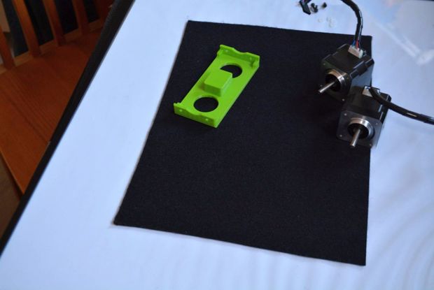
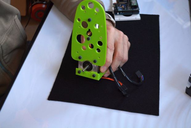
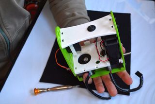
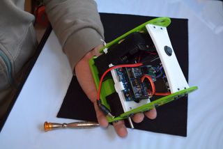
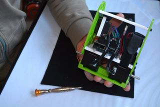
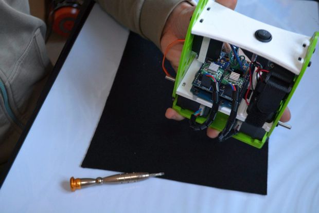
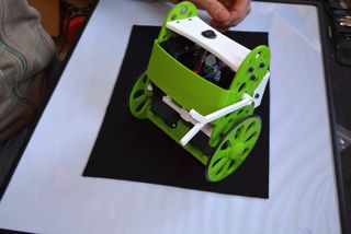
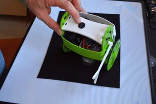
Step 2: Let’s Start Building
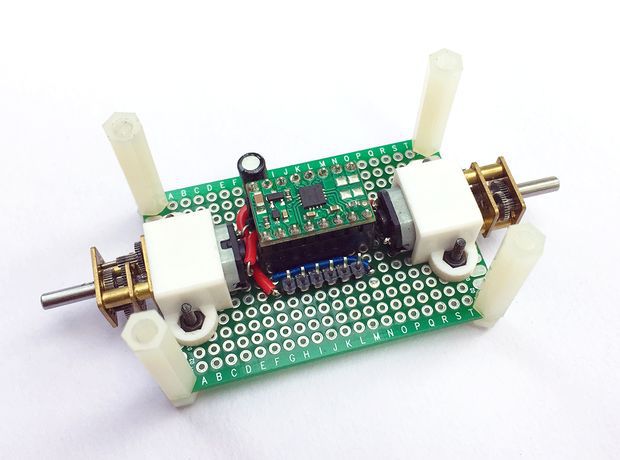
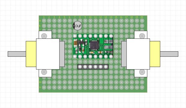
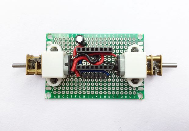
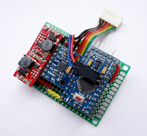
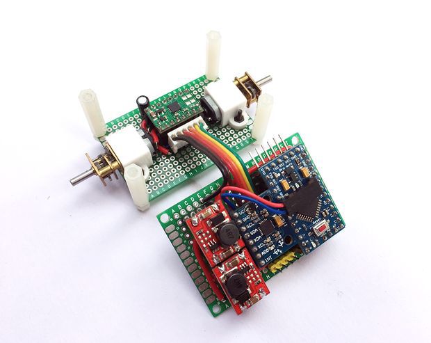
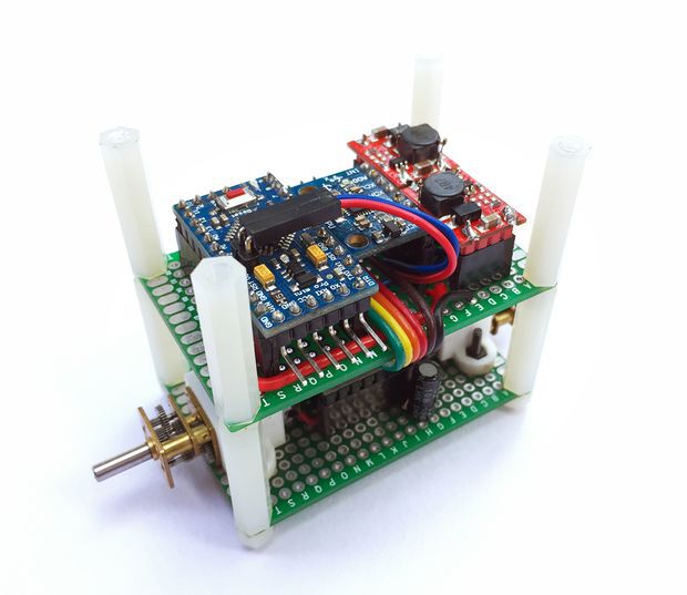
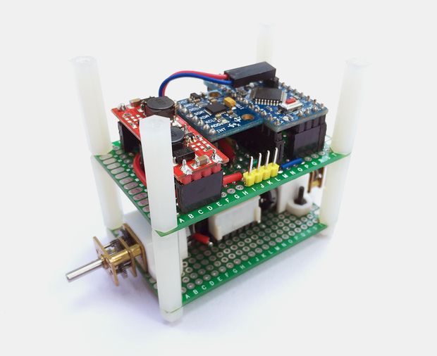
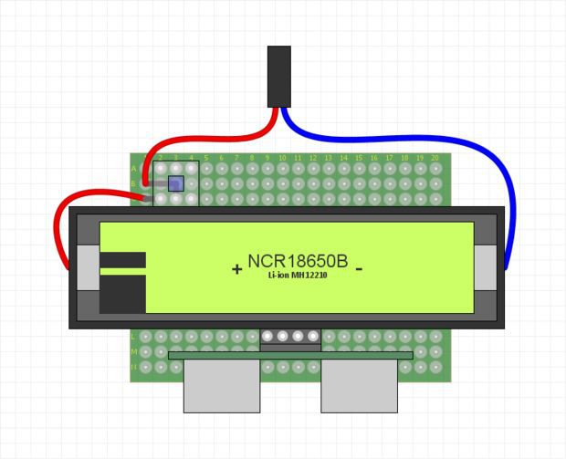
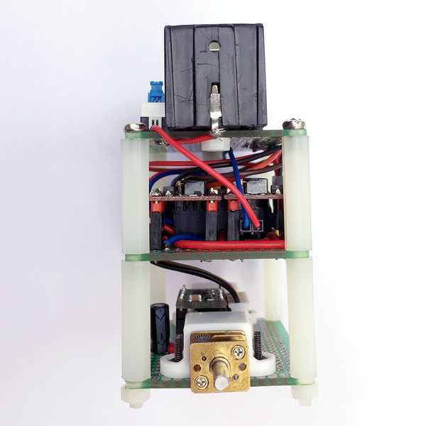
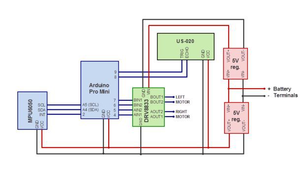
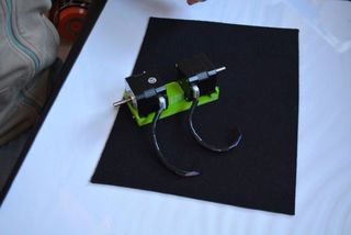
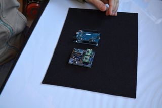
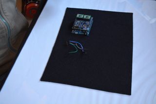
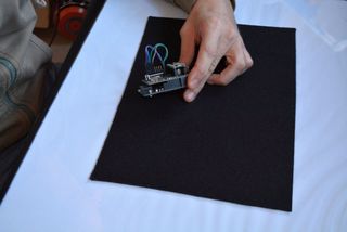
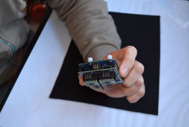
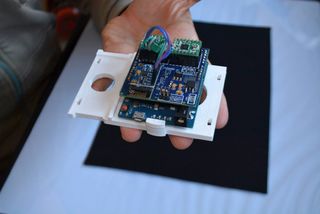
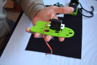
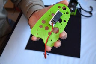
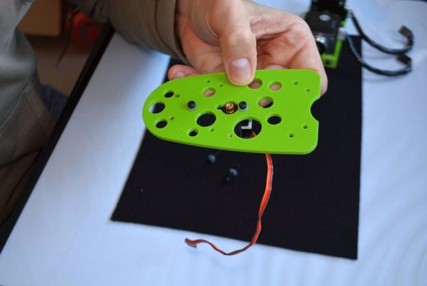
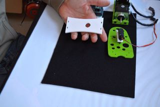
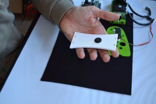
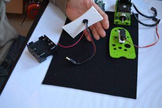
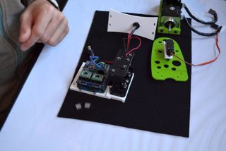
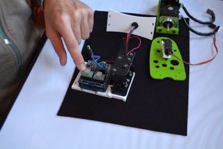
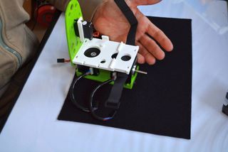
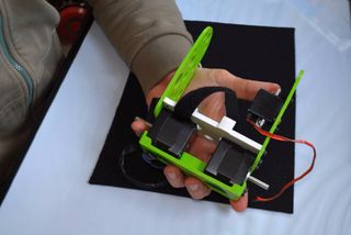
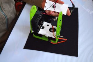
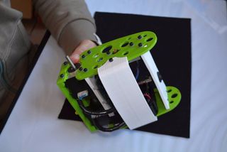
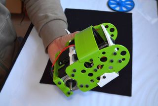
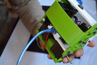
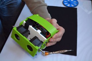
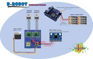
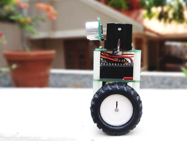
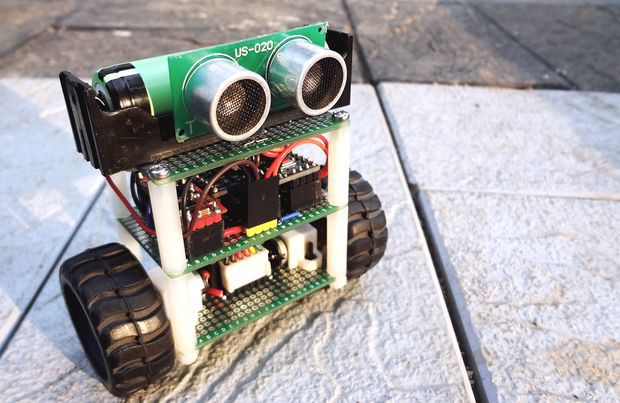
We will first complete the circuitry and structure of the robot. The robot is built on three layers of perfboards that are spaced 25mm apart using nylon spacers. The bottom layer contains the two motors and the motor driver. The middle layer has the controller, the IMU, and the 5V boost regulator modules. The top most layer has the battery, an on/off switch and the ultrasonic distance sensor (we will install this towards the end once we get the robot to balance).
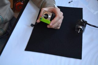
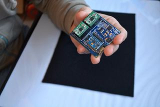
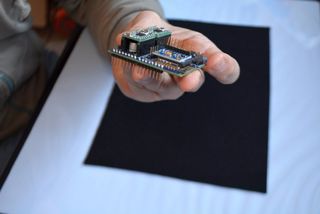
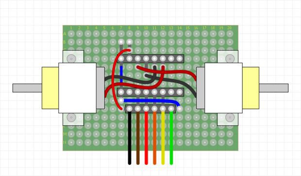
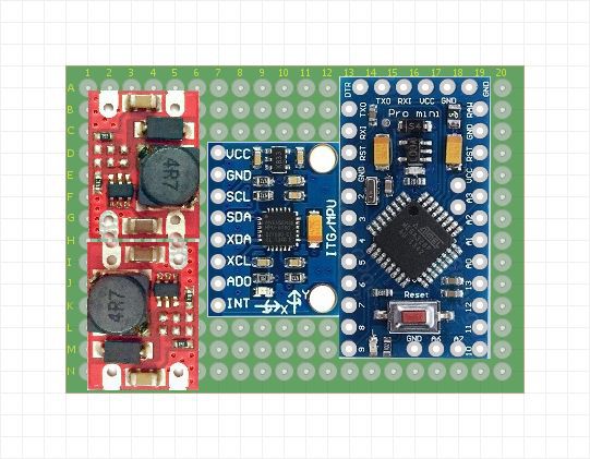
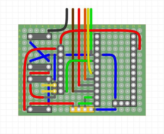
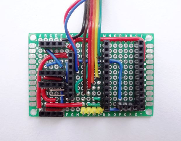
Before we begin to prototype on a perfboard we should have a clear picture about where each part should be placed. To make prototyping easy, it is always better to draw the physical layout of all the components and use this as a reference to place the components and route the jumpers on the perfboard. Once all the parts are placed and soldered, interconnect the three boards using nylon spacers.
You might have noticed that I’ve used two separate voltage regulator modules for driving the motors and the controller even though they both require a 5V source. This is very important. In my first design, I used a single 5V boost regulator to power up the controller as well as the motors. When I switched on the robot, the program freezes intermittently. This was due to the noise generated from the motor circuit acting upon the controller and the IMU. This was effectively eliminated by separating the voltage regulator to the controller and the motor and adding a 10uF capacitor at the motor power supply terminals.
Step 3: Measuring Angle of Inclination Using Accelerometer

The MPU6050 has a 3-axis accelerometer and a 3-axis gyroscope. The accelerometer measures acceleration along the three axes and the gyroscope measures angular rate about the three axes. To measure the angle of inclination of the robot we need acceleration values along y and z-axes. The atan2(y,z)function gives the angle in radians between the positive z-axis of a plane and the point given by the coordinates (z,y) on that plane, with positive sign for counter-clockwise angles (right half-plane, y > 0), and negative sign for clockwise angles (left half-plane, y < 0). We use this library written by Jeff Rowberg to read the data from MPU6050. Upload the code given below and see how the angle of inclination varies.
#include “Wire.h”
#include “I2Cdev.h” #include “MPU6050.h” #include “math.h”
MPU6050 mpu;
int16_t accY, accZ; float accAngle;
void setup() { mpu.initialize(); Serial.begin(9600); }
void loop() { accZ = mpu.getAccelerationZ(); accY = mpu.getAccelerationY(); accAngle = atan2(accY, accZ)*RAD_TO_DEG; if(isnan(accAngle)); else Serial.println(accAngle); }
Try moving the robot forward and backward while keeping it tilted at some fixed angle. You will observe that the angle shown in your serial monitor suddenly changes. This is due to the horizontal component of acceleration interfering with the acceleration values of y and z-axes.
Step 4: Measuring Angle of Inclination Using Gyroscope
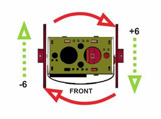
The 3-axis gyroscope of MPU6050 measures angular rate (rotational velocity) along the three axes. For our self-balancing robot, the angular velocity along the x-axis alone is sufficient to measure the rate of fall of the robot.
In the code given below, we read the gyro value about the x-axis, convert it to degrees per second and then multiply it with the loop time to obtain the change in angle. We add this to the previous angle to obtain the current angle.
#include “Wire.h”
#include “I2Cdev.h” #include “MPU6050.h”
MPU6050 mpu;
int16_t gyroX, gyroRate; float gyroAngle=0; unsigned long currTime, prevTime=0, loopTime;
void setup() { mpu.initialize(); Serial.begin(9600); }
void loop() { currTime = millis(); loopTime = currTime – prevTime; prevTime = currTime; gyroX = mpu.getRotationX(); gyroRate = map(gyroX, -32768, 32767, -250, 250); gyroAngle = gyroAngle + (float)gyroRate*loopTime/1000; Serial.println(gyroAngle); }
The position of the MPU6050 when the program starts running is the zero inclination point. The angle of inclination will be measured with respect to this point.
Keep the robot steady at a fixed angle and you will observe that the angle will gradually increase or decrease. It won’t stay steady. This is due to the drift which is inherent to the gyroscope.
In the code given above, loop time is calculated using the millis() function which is built into the Arduino IDE. In later steps, we will be using timer interrupts to create precise sampling intervals. This sampling period will also be used in generating the output using a PID controller.
Step 5: Combining the Results With a Complementary Filter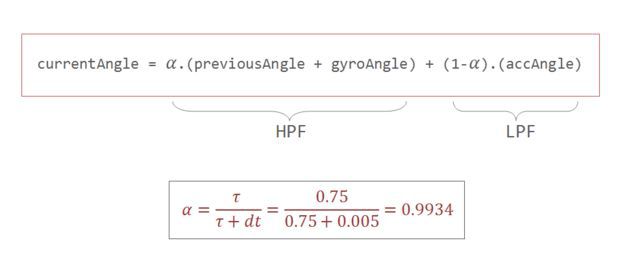
Google defines complementary as “combining in such a way as to enhance or emphasize the qualities of each other or another”.
We have two measurements of the angle from two different sources. The measurement from accelerometer gets affected by sudden horizontal movements and the measurement from gyroscope gradually drifts away from actual value. In other words, the accelerometer reading gets affected by short duration signals and the gyroscope reading by long duration signals. These readings are, in a way, complementary to each other. Combine them both using a Complementary Filter and we get a stable, accurate measurement of the angle. The complementary filter is essentially a high pass filter acting on the gyroscope and a low pass filter acting on the accelerometer to filter out the drift and noise from the measurement.
currentAngle = 0.9934 * (previousAngle + gyroAngle) + 0.0066 * (accAngle)
0.9934 and 0.0066 are filter coefficients for a filter time constant of 0.75s. The low pass filter allows any signal longer than this duration to pass through it and the high pass filter allows any signal shorter than this duration to pass through. The response of the filter can be tweaked by picking the correct time constant. Lowering the time constant will allow more horizontal acceleration to pass through.
Eliminating accelerometer and gyroscope offset errors
Download and run the code given in this page to calibrate the MPU6050’s offsets. Any error due to offset can be eliminated by defining the offset values in the setup() routine as shown below.
mpu.setYAccelOffset(1593);
mpu.setZAccelOffset(963); mpu.setXGyroOffset(40);
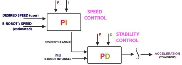
Step 6: PID Control for Generating Output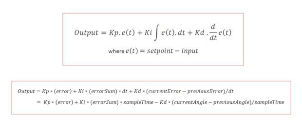
PID stands for Proportional, Integral, and Derivative. Each of these terms provides a unique response to our self-balancing robot.
The proportional term, as its name suggests, generates a response that is proportional to the error. For our system, the error is the angle of inclination of the robot.
The integral term generates a response based on the accumulated error. This is essentially the sum of all the errors multiplied by the sampling period. This is a response based on the behavior of the system in past.
The derivative term is proportional to the derivative of the error. This is the difference between the current error and the previous error divided by the sampling period. This acts as a predictive term that responds to how the robot might behave in the next sampling loop.
Multiplying each of these terms by their corresponding constants (i.e, Kp, Ki and Kd) and summing the result, we generate the output which is then sent as command to drive the motor.
Step 7: Tuning the PID Constants
1. Set Ki and Kd to zero and gradually increase Kp so that the robot starts to oscillate about the zero position.
2. Increase Ki so that the response of the robot is faster when it is out of balance. Ki should be large enough so that the angle of inclination does not increase. The robot should come back to zero position if it is inclined.
3. Increase Kd so as to reduce the oscillations. The overshoots should also be reduced by now.
4. Repeat the above steps by fine tuning each parameter to achieve the best result.
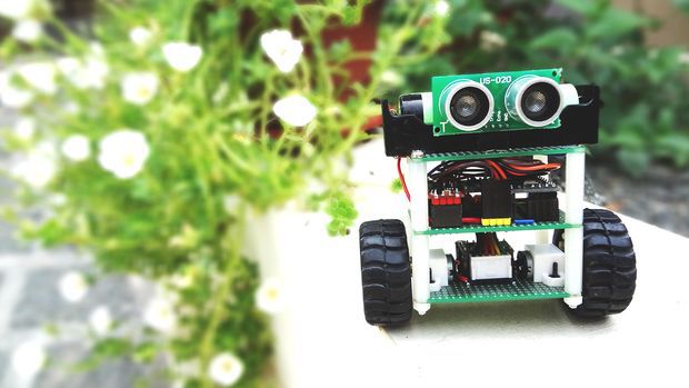
Step 8: Adding the Distance Sensor
The ultrasonic distance sensor that I’ve used is the US-020. It has four pins namely Vcc, Trig, Echo, and Gnd. It is powered by a 5V source. The trigger and echo pins are respectively connected to digital pins 9 and 8 of Arduino. We will be using the NewPing library to get the distance value from the sensor. We will read the distance once every 100 milliseconds and if the value is between 0 and 20cm, we will command the robot to perform a rotation. This should be sufficient to steer the robot away from the obstacle.
Step 9: The Complete Code
#include "Wire.h"
#include “I2Cdev.h” #include “MPU6050.h” #include “math.h” #include <NewPing.h>
#define leftMotorPWMPin 6 #define leftMotorDirPin 7 #define rightMotorPWMPin 5 #define rightMotorDirPin 4
#define TRIGGER_PIN 9 #define ECHO_PIN 8 #define MAX_DISTANCE 75
#define Kp 40 #define Kd 0.05 #define Ki 40 #define sampleTime 0.005 #define targetAngle -2.5
MPU6050 mpu; NewPing sonar(TRIGGER_PIN, ECHO_PIN, MAX_DISTANCE);
int16_t accY, accZ, gyroX; volatile int motorPower, gyroRate; volatile float accAngle, gyroAngle, currentAngle, prevAngle=0, error, prevError=0, errorSum=0; volatile byte count=0; int distanceCm;
void setMotors(int leftMotorSpeed, int rightMotorSpeed) { if(leftMotorSpeed >= 0) { analogWrite(leftMotorPWMPin, leftMotorSpeed); digitalWrite(leftMotorDirPin, LOW); } else { analogWrite(leftMotorPWMPin, 255 + leftMotorSpeed); digitalWrite(leftMotorDirPin, HIGH); } if(rightMotorSpeed >= 0) { analogWrite(rightMotorPWMPin, rightMotorSpeed); digitalWrite(rightMotorDirPin, LOW); } else { analogWrite(rightMotorPWMPin, 255 + rightMotorSpeed); digitalWrite(rightMotorDirPin, HIGH); } }
void init_PID() { // initialize Timer1 cli(); // disable global interrupts TCCR1A = 0; // set entire TCCR1A register to 0 TCCR1B = 0; // same for TCCR1B // set compare match register to set sample time 5ms OCR1A = 9999; // turn on CTC mode TCCR1B |= (1 << WGM12); // Set CS11 bit for prescaling by 8 TCCR1B |= (1 << CS11); // enable timer compare interrupt TIMSK1 |= (1 << OCIE1A); sei(); // enable global interrupts }
void setup() { // set the motor control and PWM pins to output mode pinMode(leftMotorPWMPin, OUTPUT); pinMode(leftMotorDirPin, OUTPUT); pinMode(rightMotorPWMPin, OUTPUT); pinMode(rightMotorDirPin, OUTPUT); // set the status LED to output mode pinMode(13, OUTPUT); // initialize the MPU6050 and set offset values mpu.initialize(); mpu.setYAccelOffset(1593); mpu.setZAccelOffset(963); mpu.setXGyroOffset(40); // initialize PID sampling loop init_PID(); }
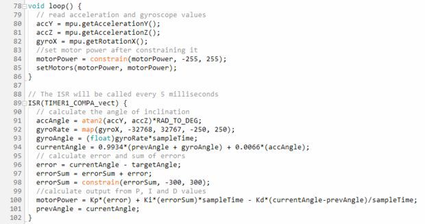
void loop() { // read acceleration and gyroscope values accY = mpu.getAccelerationY(); accZ = mpu.getAccelerationZ(); gyroX = mpu.getRotationX(); // set motor power after constraining it motorPower = constrain(motorPower, -255, 255); setMotors(motorPower, motorPower); // measure distance every 100 milliseconds if((count%20) == 0){ distanceCm = sonar.ping_cm(); } if((distanceCm < 20) && (distanceCm != 0)) { setMotors(-motorPower, motorPower); } } // The ISR will be called every 5 milliseconds ISR(TIMER1_COMPA_vect) { // calculate the angle of inclination accAngle = atan2(accY, accZ)*RAD_TO_DEG; gyroRate = map(gyroX, -32768, 32767, -250, 250); gyroAngle = (float)gyroRate*sampleTime; currentAngle = 0.9934*(prevAngle + gyroAngle) + 0.0066*(accAngle); error = currentAngle – targetAngle; errorSum = errorSum + error; errorSum = constrain(errorSum, -300, 300); //calculate output from P, I and D values motorPower = Kp*(error) + Ki*(errorSum)*sampleTime – Kd*(currentAngle-prevAngle)/sampleTime; prevAngle = currentAngle; // toggle the led on pin13 every second count++; if(count == 200) { count = 0; digitalWrite(13, !digitalRead(13)); } }
Step 10: Final Thoughts
Spending a bit more time on tweaking the PID constants would give us a better result. The size of our robot also limits the level of stability we can achieve. It is easier to build a full-sized balancing robot than it is to build a small one like ours. Still, I guess, our robot does a pretty decent job in balancing on various surfaces as shown in the video.
That’s it for now.
Thanks for your time. Don’t forget to leave your thoughts in the comments section.