
After my first fast made self balancing robot, I want to better understand it and especially to try different control methods. For me it is necessary to simulate the whole stuff on computer (robot + control law).
The first step is therefore to model the robot with mathematical equations. Because of the complexity of the model I do make some assumption and simplification.
The model is separated into three part: the DC motor, the wheel and the inverted pendulum
The DC motor
electrical model:

wtih
equation of motion for the motor:
with
If the motor inductance and friction torque are neglected, then
in state space form:
The inputs to the motor is the applied voltage and applied torque on the rotor.
The wheel

in horizontal (x direction):
rotation equation around the center of the wheel:
by using motor dynamic equations, one can get
with
then
Above equation is valid for both wheels.
With following equations, one can translate the angular rotate to linear motion:
then
After rearrangement, one has:
The inverted pendulum

horizontal:
The sum of forces perpendicular to the pendulum:
The sum of motions around the center of mass of pendulum:
with
one has:
then
then
and
after arrangement, one can get the following state space expression:
with
On my first two-wheel self-balancing robot, I didn’t use the encoder for speed measurement.
So it can basically stand still and balance its weight with small movements of its two
wheels simultaneously. I preferred that the robot would work very soon without much effort
and then I could improve it by adding speed control, RC, etc.
1.Hardware
It’s not difficult to gather all the parts. Here is my list:
1.glass fiber board
2.control board (arduino uno)
3.sensor board (MPU6050 gyroscope + accelerameter)
4.two-channel motor driver (L298N)
5.two geared DC motors (25GA370)
6.two toy wheels and fixation kit
Following is my assembly diagram:

Following is the wiring diagram:

In L298N, each motor is controlled by a full bridge circuit (or H-bridge) composed of two legs. Following figure is a simplified diagram coming from wikipedia. S1 and S2 are always controlled in complementary manner. When S1 closes, S2 opens. S1 and S2 close simultaneously is not allowed since that creates a short circuit of the power supply. Idem for S3 and S4.

When S1 and S4 close simultaneously, the motor rotates in one direction. When S3 and S2 close simultaneously, the motor rotates in the other direction. I use PWM control to set the motors’ speed. the switching frequency is about 1kHz which is the default value of Arduino module.
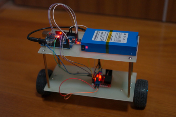
After the wiring, the robot looks like:

2.Control
Then comes the control part. The following figure shows the control diagram. Only the inner
loop in blue is implemented this time. I use it to regulate the tilt angle of the robot. As
I want the robot stands straight, I simply set the reference angle (REF_ANGLE) to 0. The
gyro+acc sensor gives the information needed to calculate the actual tilt angle. The error
between the reference and the measurement is used by the PID controller to give the command
to the robot (the two wheel motors).

2.1 PID controller
The PID controller is a complexe topic. With google you can find tons of material about it.
Fortunately it is relatively simple to implement it in a microcontroller. With some basic
understanding and tuning techniques, one can make it work very easily.
The general mathematical form of the PID controller is (extracted from wikipedia):
Here is a simple software loop that implements a PID algorithm (extracted from wikipedia):
previous_error = 0
integral = 0
start:
  error = setpoint - measured_value
  integral = integral + error*dt
  derivative = (error - previous_error)/dt
  output = Kp*error + Ki*integral + Kd*derivative
  previous_error = error
  wait(dt)
  goto start
The purpose of the PID controller is to generate a suitable command to the system (the self
balancing robot in this case) so that the system is stable and reactive. There are some
creteria of both the static and dynamic performance. But they are out of the scope. The PID
controller uses three parameters to do the job, the proportional (Kp), integral (Ki),
derivative(Kd) parameter. The big Kp makes the tilt angle error small and the reaction fast. The
Ki makes the static angle error dispear. This is important since I want the robot stands
straight (tilt angle=0) all the time. I choose to put Kd=0 because Ki and Kp achieve
perfectly my desired performance. So in fact I use a PI controller. For the PI parameter
tuning, I follow Ziegler-Nichols method that you can find on wikipedia. Following table is
copied from wikipedia. It works well for me.

2.2 Tilt angle measurement
A sensor combining a gyroscope and an accelerometer is used to measure the tilt angle. The sensor don’t give the angle directly. Some calculation is needed. I use MP6050 as sensor. You can check its datasheet for more information.
The accelerometer gives the acceleration (unit g) in three dimension. If the robot is perpendicular to the earth (z axis for example), you should have only Z axis which is not zero. If you have another axis not equaling zero besides Z axis in static state, it means the robot has a none zero tilt angle. And you can get easily the tilt angle based on these two axis acceleration. However using accelerometer to get the tilt angle in this way is valid only for static state since we suppose that only gravity acts on the robot. When the two wheels act a force on the robot, the accelerometer can measure the resulting acceleration as well! In consequence, the measures are very noised. The good point is it is accurate in long period of time (or in DC after filtering).
The gyroscope measures the angle speed (unit deg/s) in three dimension. In order to get the angle, we need to do the integration of it. It is accurate dynamically (in short period). But the integration action accumulates the error of measurement, which makes the result drift in long period of time.
I use a complementary filter to combine the two sensor measurements. It is simple and needs little microcontroller calculation. It works well for me (so far). One can implement kalman filter for optimal control. But the knowledge of the system model and more calculation capability are required. It needs definitely more effort. I use following complementary filter to get the tilt angle estimation:
3.Software
The sensor communicates to the microcontroller through I2C bus. By using the WIRE library of arduino, it is easy to read the data. I use analogWrite function to set PWM duty cycle for the motor driver L298N. The command (PID controller’s output) is a value between -255 and 255. Positive sign means the robot moves forward. 255 represents the max speed (100% duty cycle for the first half bridge). I use anti-windup code to prevent the command to be higher than 255 (or lower than -255) which is the limit of PWM register (8 bits) max value.
The calibration of the sensor should be done generally. I calibrated the gyroscope because I see big static offset. My accelerometer’s offset is not obvious. I use 10ms as sampling time.
The total code has only about 50 lines which I believe possible to be optimized. It’s simple, right? 
4.Conclusion
The robot resists relatively well the disturbance from both sides. The stability and dynamic response are satisfactory. The next step is to install an encoder on each motor, to make the robot possible to move and to add a remote control. Following is a video of it standing still.