Tag: DIY
LED Matrix Bar Weather Station V2 – Design
nRF24 RC Transmitter – Exploded View
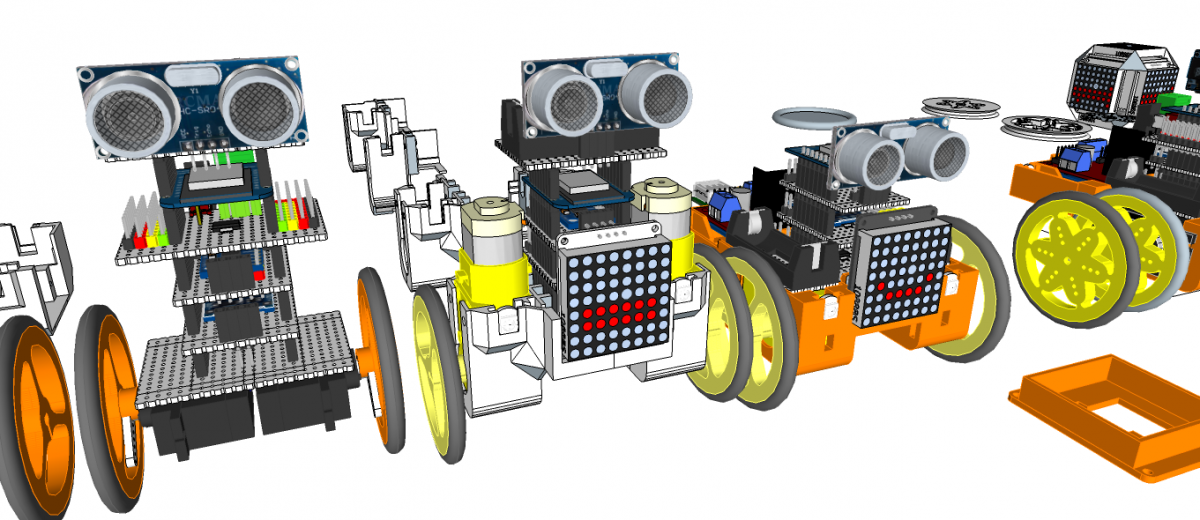
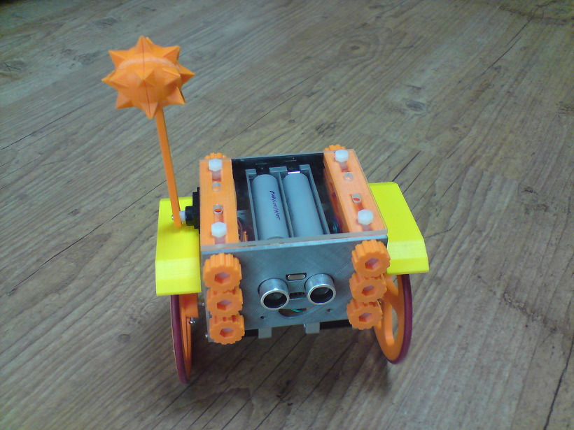
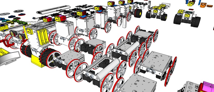
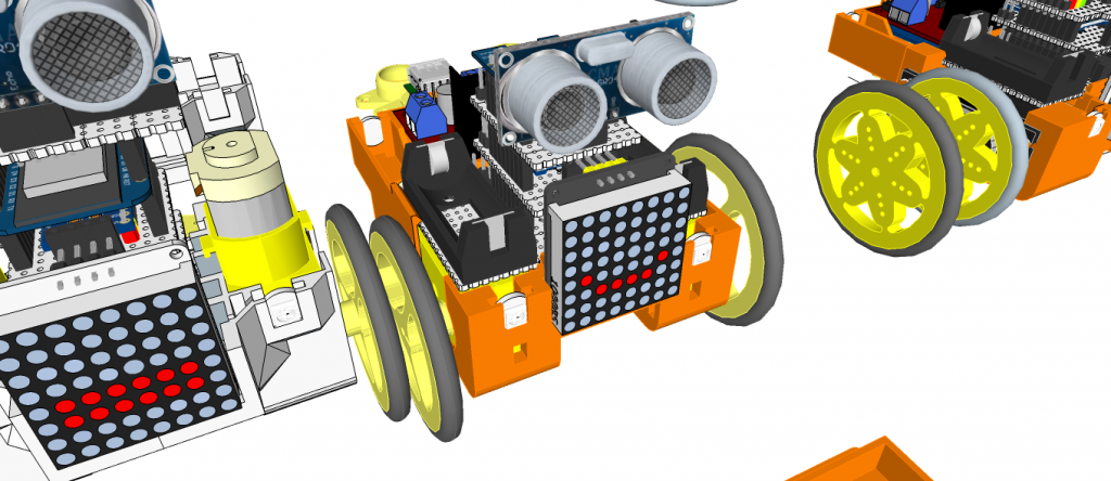
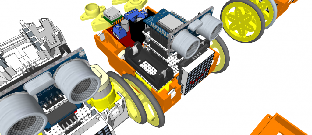
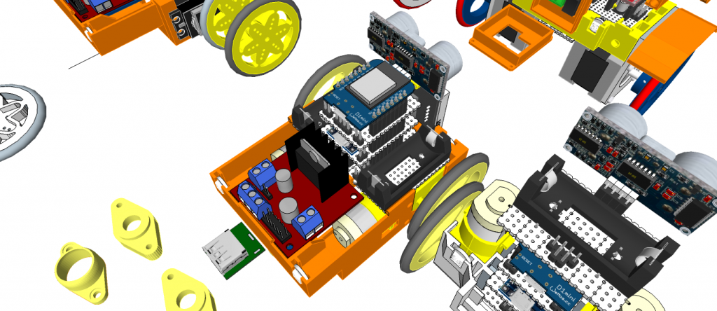
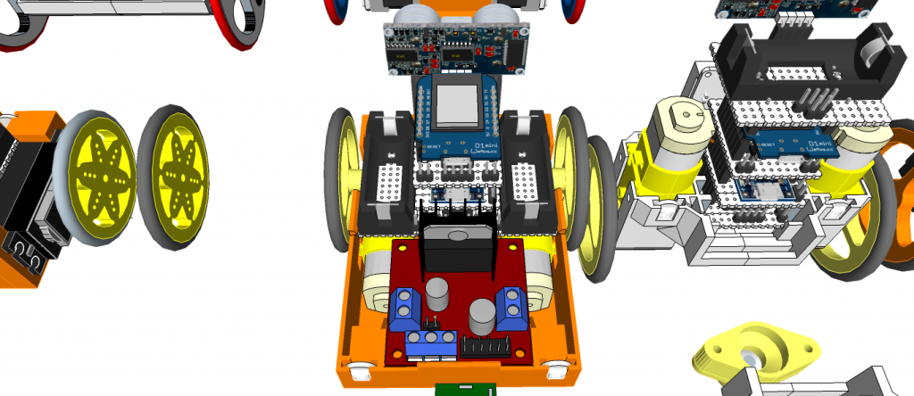
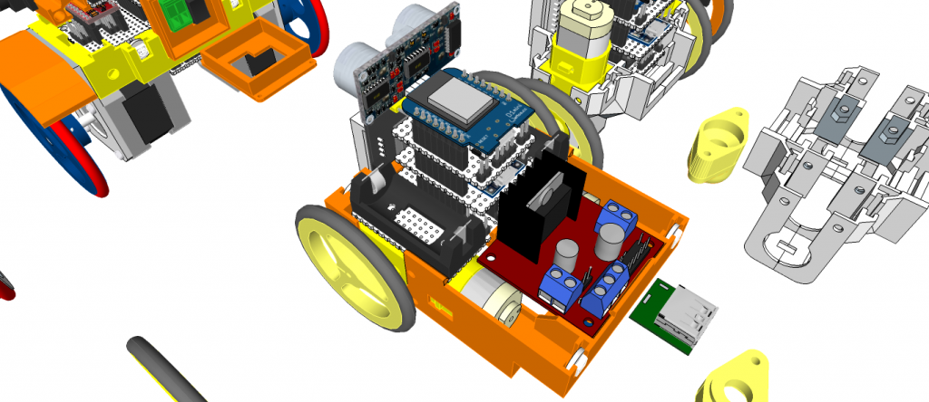
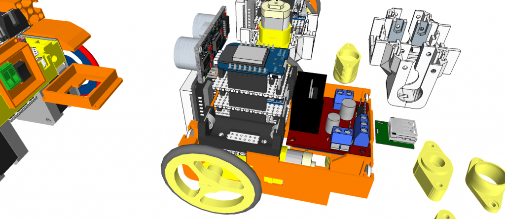
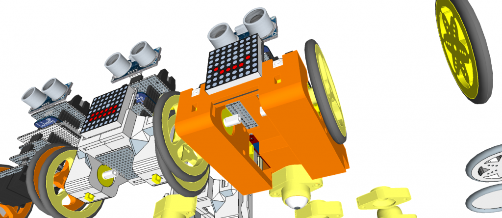
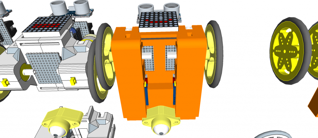
miniMe™ – DIY mini Robot Platform – Design Concepts
miniMe™ is 3D printing DIY mini robot platform
- Balancing Robot
- Rover
- Line Tracer
- Etc…
miniMe-BB: TT motor type
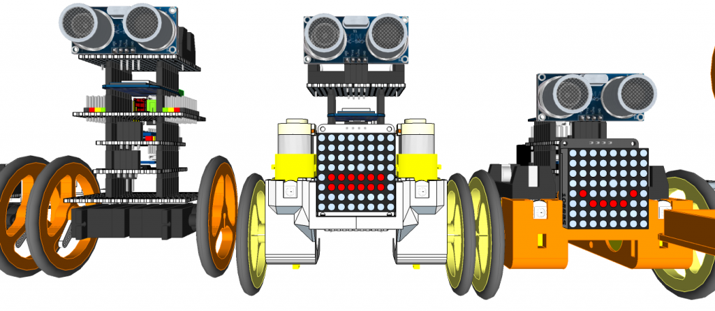
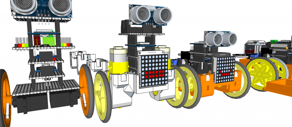
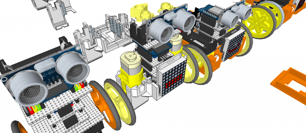
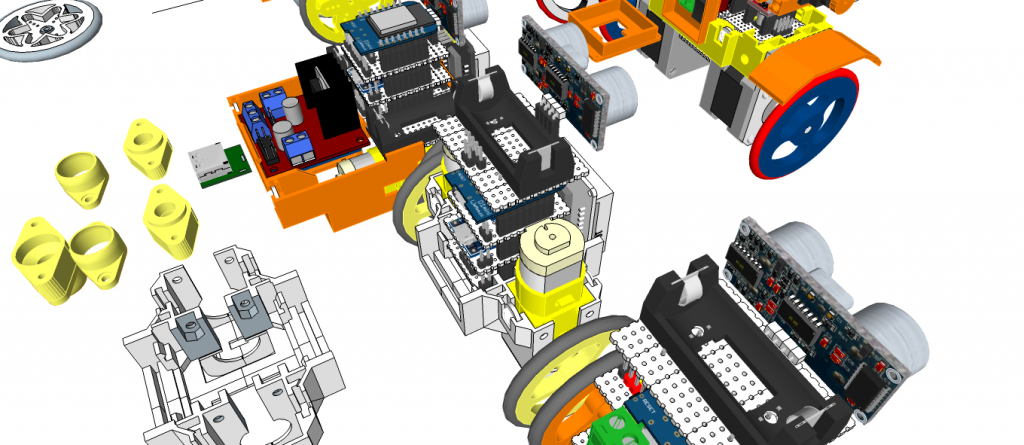
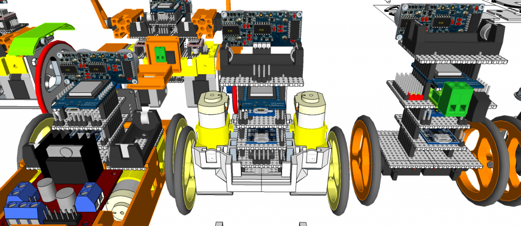
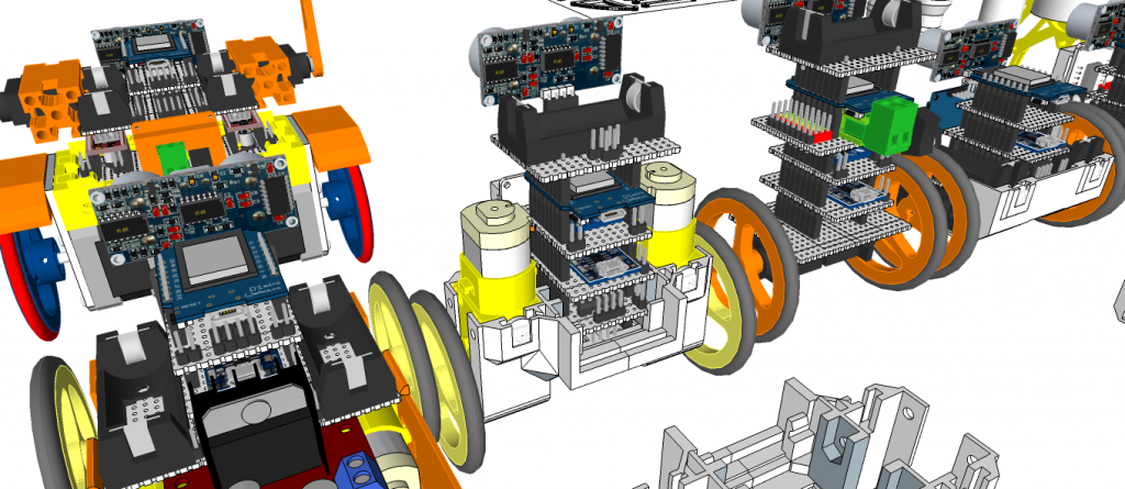
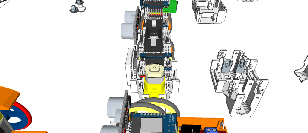
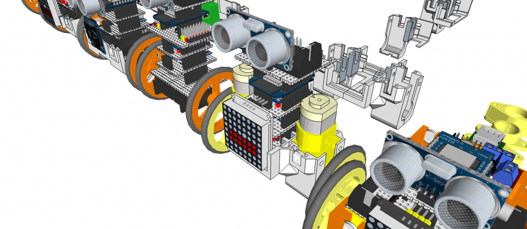
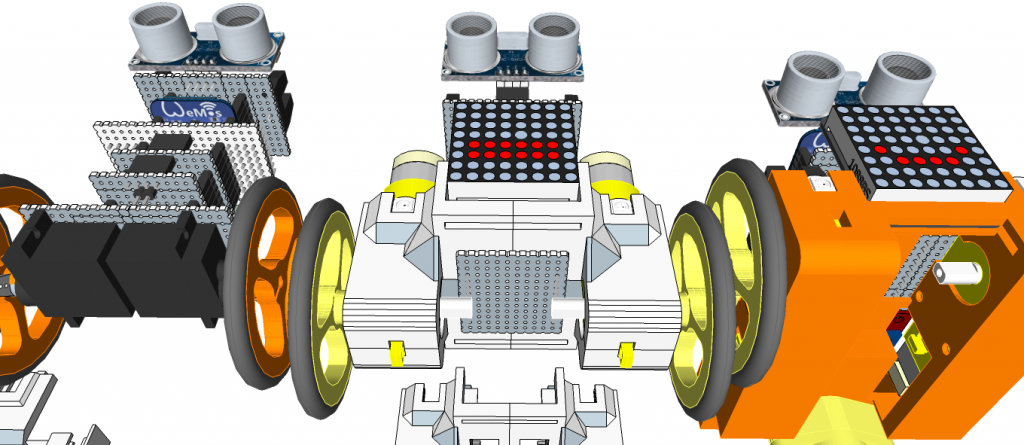 miniMe-BB: N20 motor type
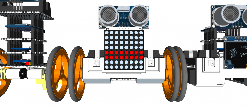
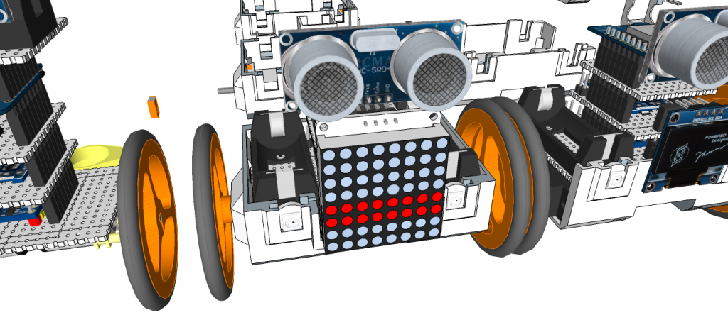
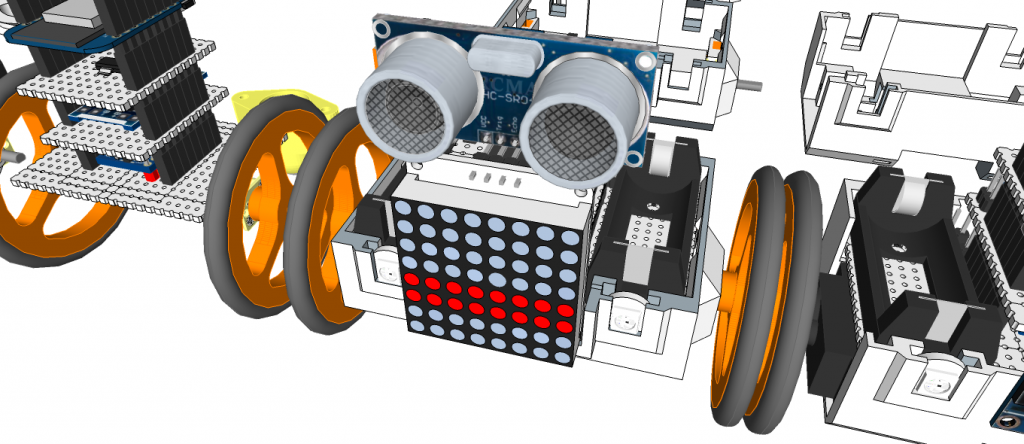
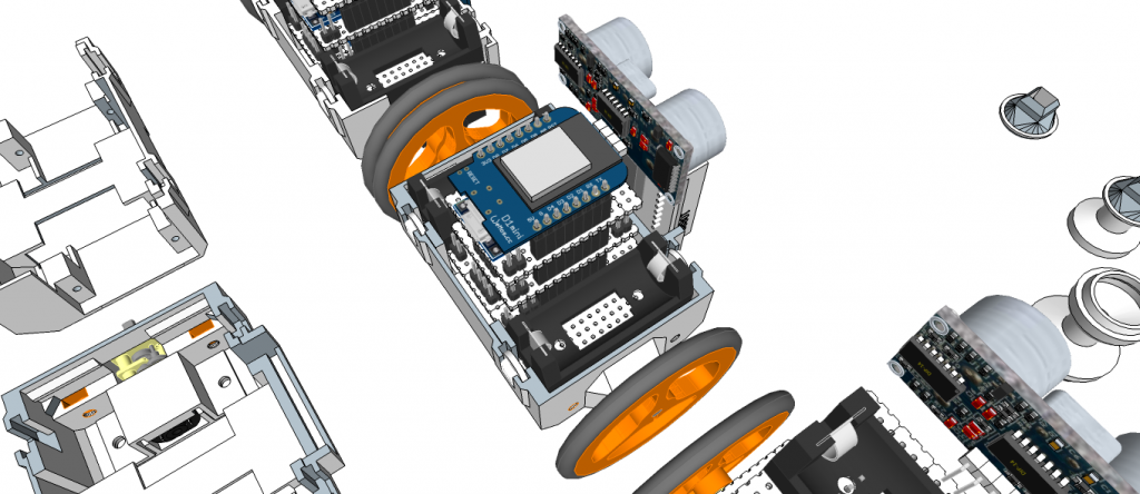
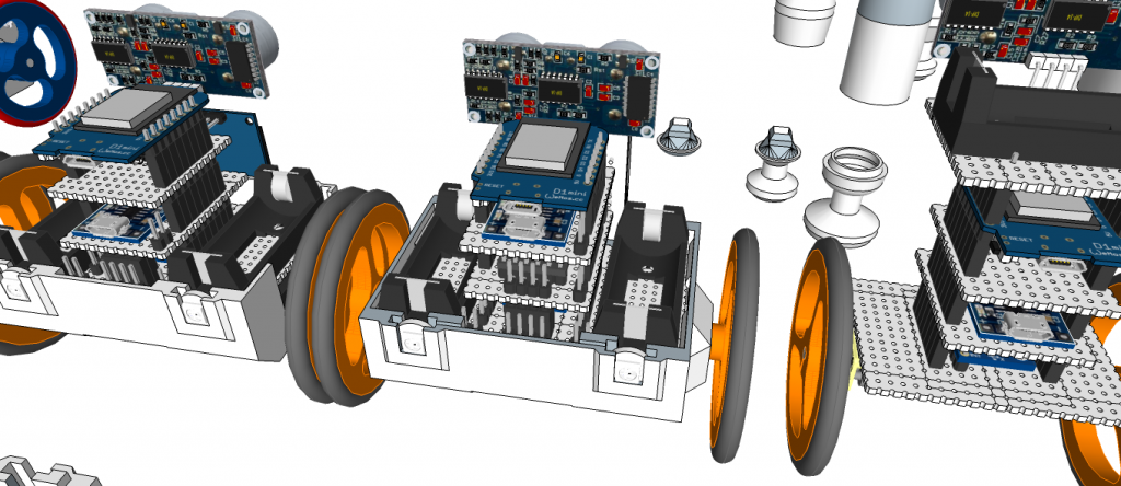
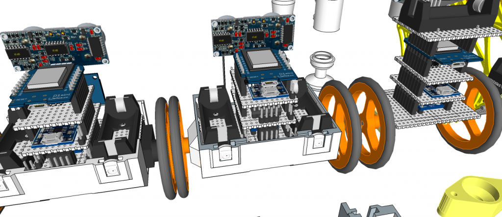
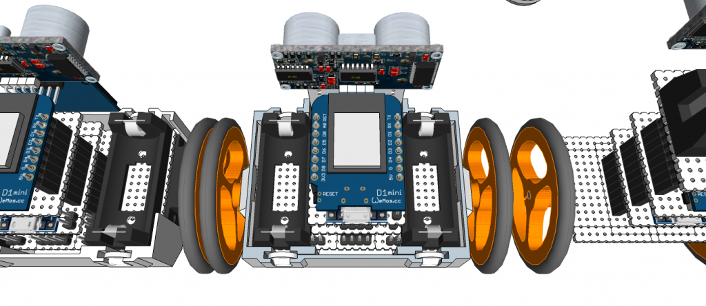
miniMe-BB: SG90 Servo Motor type
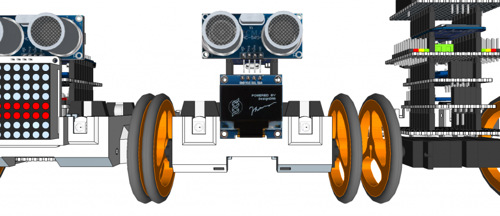
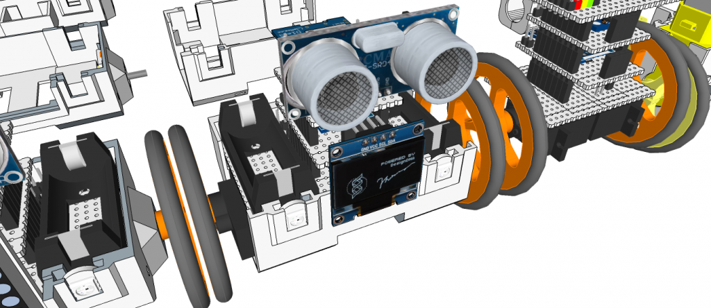
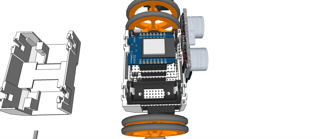
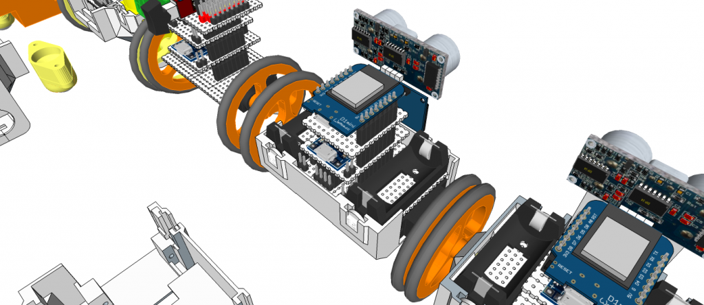
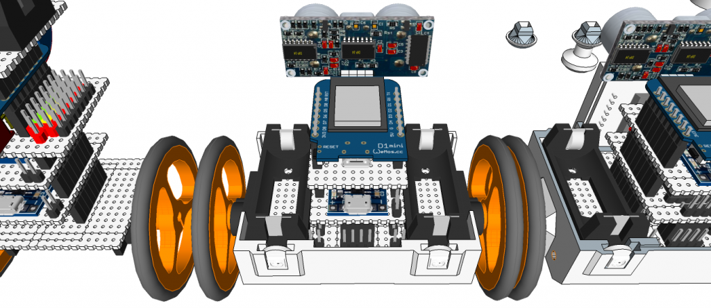
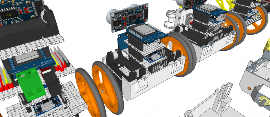
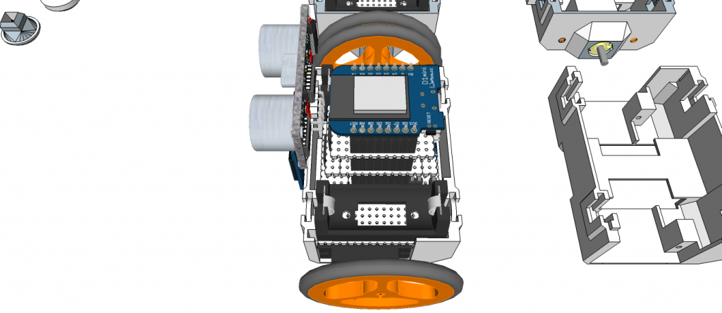
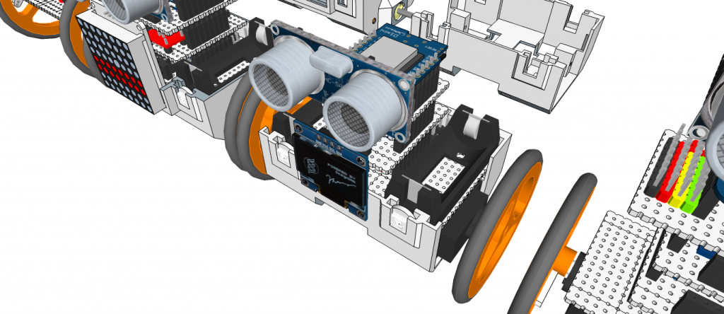
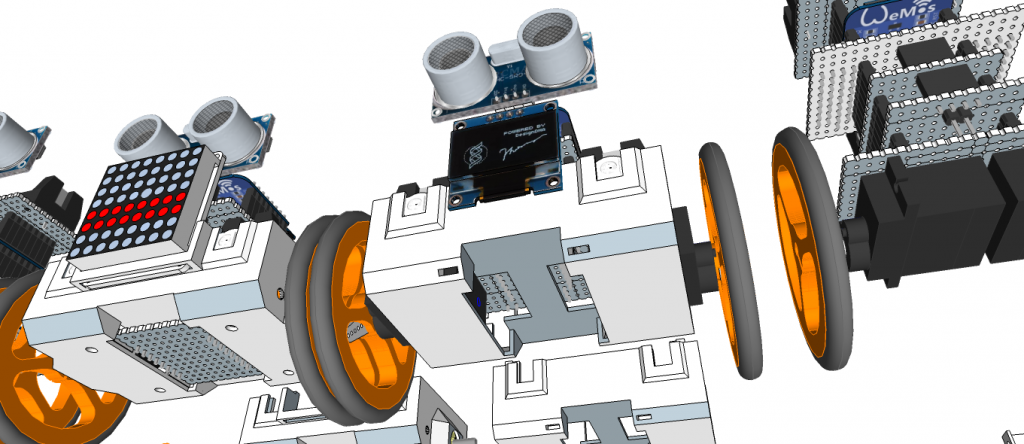
miniMe-Rover: Servo motor type (Standard Servo)
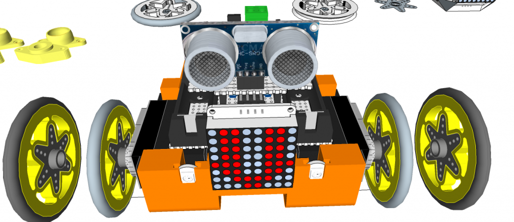
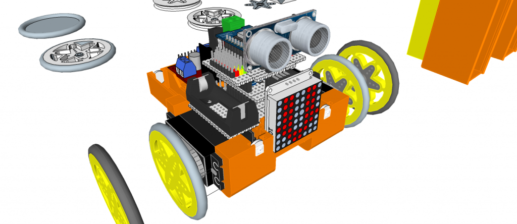
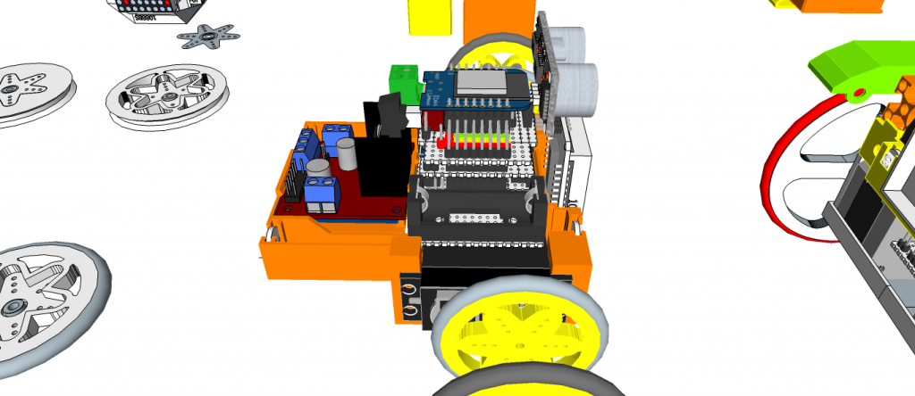
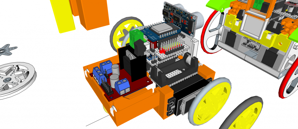
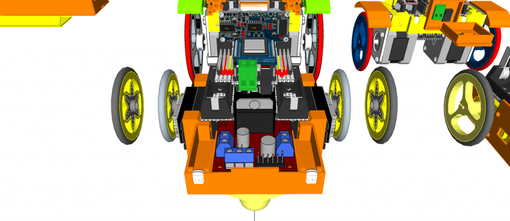
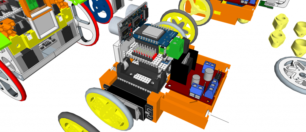
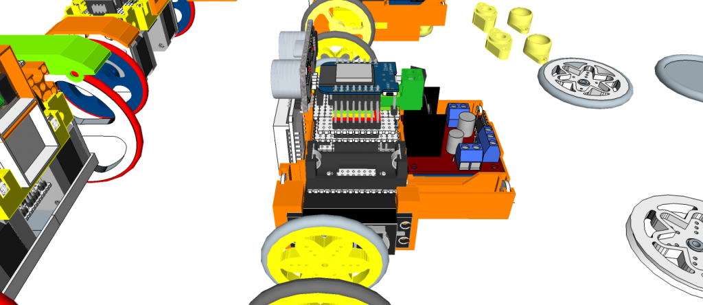
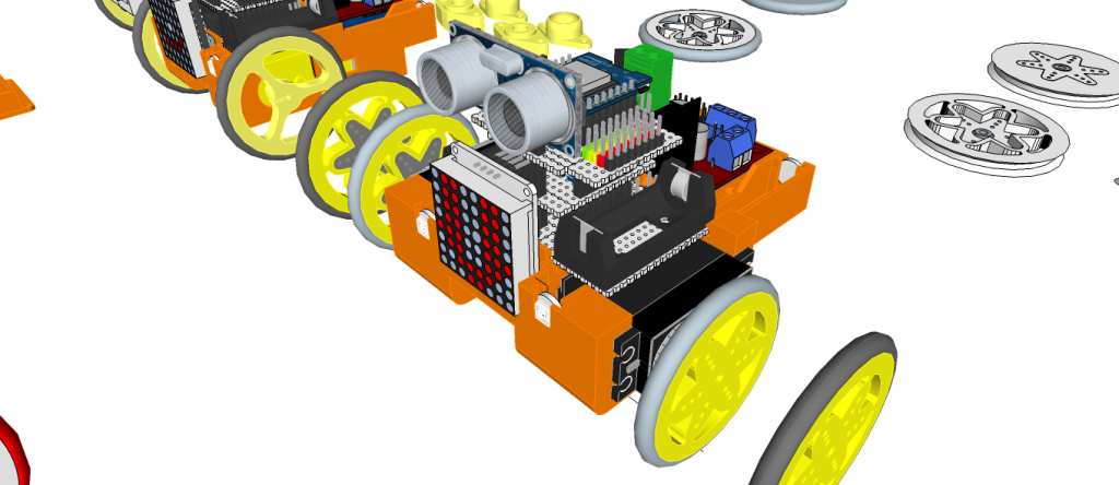
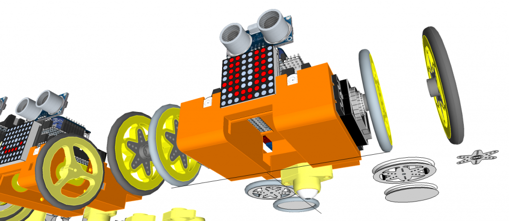
miniMe-Rover: TT motor type
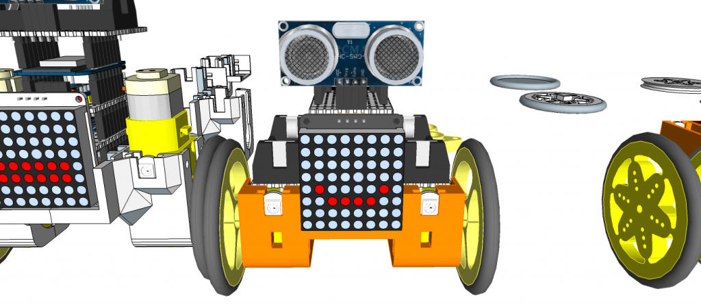
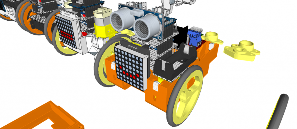
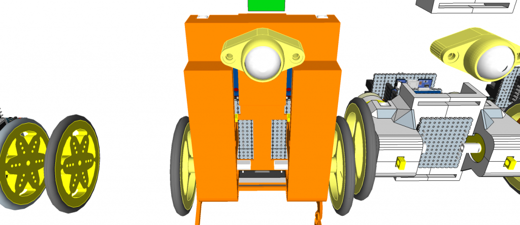
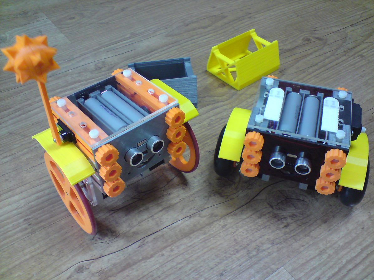
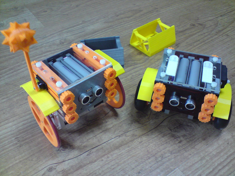
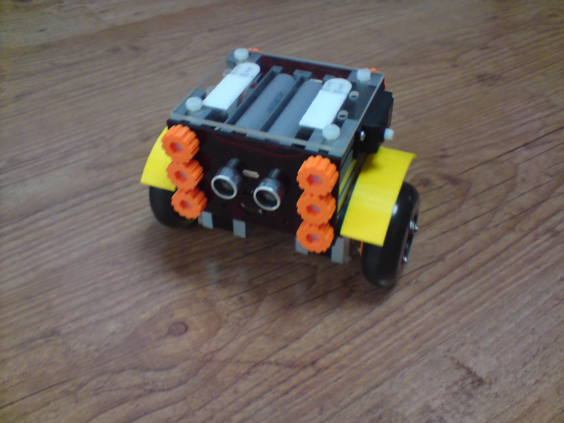
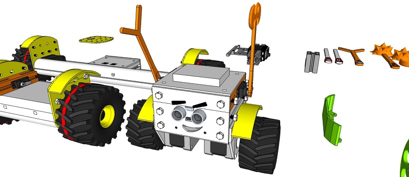
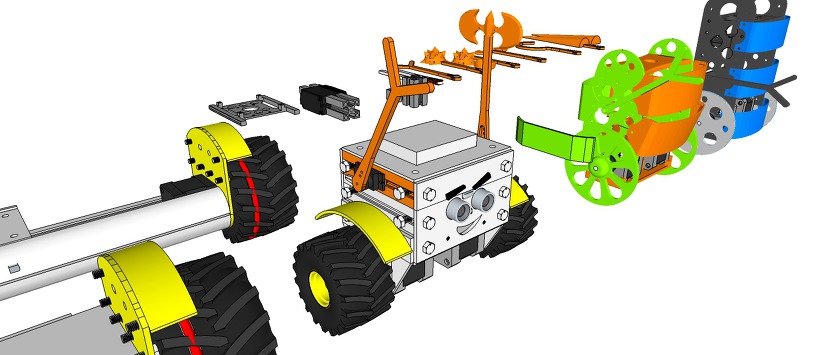
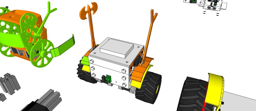
eX-Robot – ProfileBlock™ Robot Platform
[ Upload 20170424]
[ Upload design concept 20170418]
http://www.thingiverse.com/thing:2256715
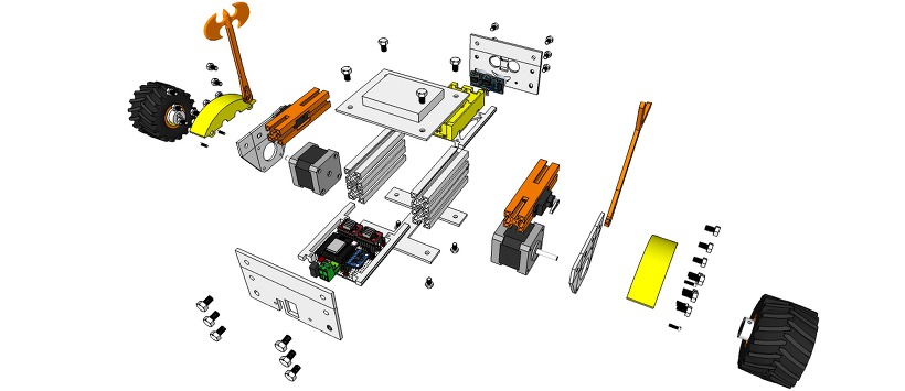
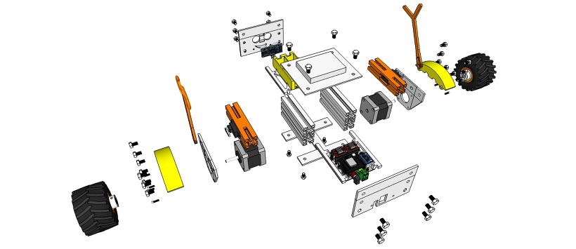
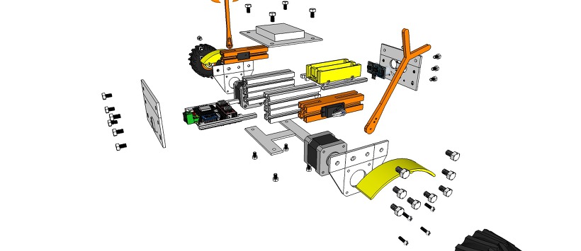
ProfileBlock – Balancing Robot – DIY Robots Platform
3D Design Tool: SketchUp Pro
ProfileBlock’s robots are built on top of an open source Arduino-based(with ESP8266, Raspberry Pi) platform.
Self Balancing Robot (eX-Robot, B-Robot, Roverbot, …
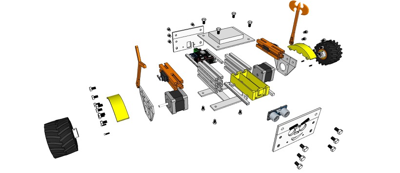
Hardware_____
Base Plate(Parts):
6 x ProfileBlock™ DF 2020 85mmAcrylic Plate (t = 3mm)1 x Top Plate1 x Bottom Plate
2 x Step Motor Mount Plate
1 x Front Plate
1 x Rear Plate3D Printing Parts
2 x Servo Mount ProfoleBlock
12 x Knob M5 Hexaheard
2 x Wheels 100mm or Inline Wheels 70mm(with 2 x Inline Wheels Hub)
2 x Tire Mudguards
1 x Stand1 x Battery Holder
Step Motor:
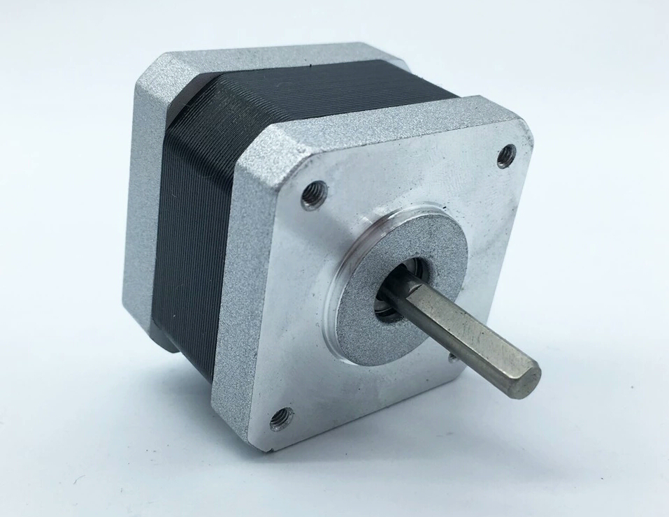
2 x Nema 17 Stepper Motor bipolar 4 leads 34mm 12V 1.3A 26Ncm(36.8oz.in) 3D printer motor 42SHD0001
2 x NEMA 17 – Phase: 4, Step Angle: 1.8 Deg/Step, Holding Torque: 2.6Kg.cm
Servo:
1 x Standard Servo or SG90 Metal Servo
1 x Standard Servo (Option) or SG90 Metal Servo
12 x M5 10mm Nylon Bolts
12 x M5 8mm Nylon Bolts
12 x M5 Nylon Nuts
8 x M3 8mm Bolts
4 x M3 10mm Bolts
4 x M3 15mm Bolts
8 x M3 Nuts
Electrical______
Control Board:
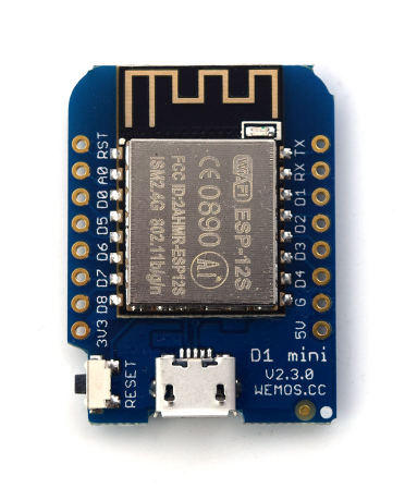
1 x ESP8266 Witty Cloud or WeMos (eX-Robot)
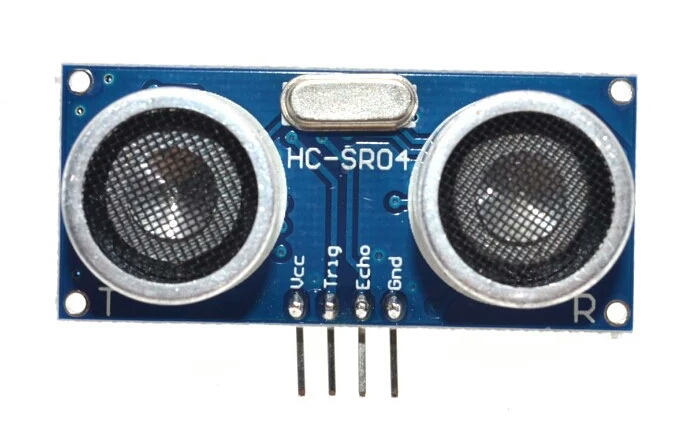
1 X MPU6050
2 x A4988 Step Motor Drive
1 x LM1117-5.0 5,0V 1A Regulator
1 x LM1117-3,3 3,3V 1A Regulator
6 x 100uF 25V Capacitor
4 x 0.1uF Capacitor
1 x 220KOhm Resistor
1 x 100KOhm Resistor
4 x 10KOhm Resistor
7 x 8P Female Pin Header Connector 2.54mm Pitch
3 x 4P Male Pin Header Connector 2.54mm Pitch
2 x 3P Male Pin Header Connector 2.54mm Pitch
3 x 2P Male Pin Header Connector 2.54mm Pitch
1 x 2EDGK 5.08mm 2P Plug-in terminal connectors set
1 x Interface Mother boardPower Requirements:8.4VDC
12 VDCBattery:2 x 18650 Litum Ion Battery = 7.2 VDC ~ 8.4 VDCSoftware:
Arduino IDE (ESP8266 ESP-12E/F)Support SoftAP and StationSupport OTA (at Local network)Support mDNS (at Local network)
The open source ProfileBlock hardware and software is free and made with love. Please show your level of support with a voluntary donation.
Donate:
https://www.paypal.com/cgi-bin/webscr?cmd=_s-xclick&hosted_button_id=RDN7ZGAVFS5UE
How to Build an Arduino Self-Balancing Robot
By Roland Pelayo
Ever wonder how Segways work? This tutorial will show you how to build an Arduino self-balancing robot that balances itself — just like a Segway!
How Does Balancing Work?
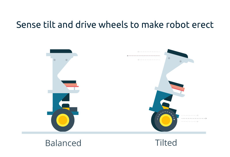
To keep the robot balanced, the motors must counteract the fall of the robot. This action requires a feedback and a correcting element. The feedback element is the MPU6050 gyroscope + accelerometer, which gives both acceleration and rotation in all three axis (MPU6050 I2C basics) which is used by the Arduino to know the current orientation of the robot. The correcting element is the motor and wheel combination.
Required Materials
- Arduino (UNO or Nano can be used. I used Nano for this project.)
- MPU6050 gyro+accelerometer breakout board.
- L298N driver module
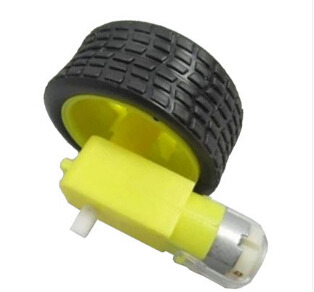
- 2 x Geared DC Motor+wheels
- Three platforms (PCB, acrylic, or thick plastic)
- Posts to hold the platforms
- Jumper wires
- Headers
- Battery Pack
Connection Diagram
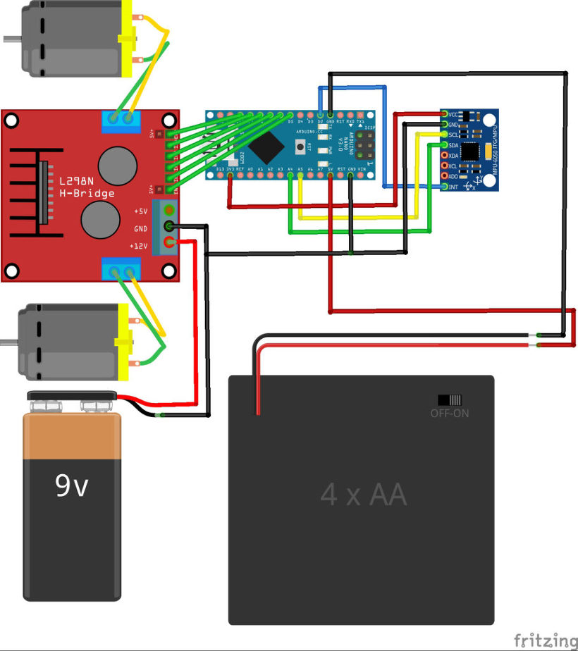
Connect the MPU6050 to the Arduino first and test the connection using the codes in this IMU interfacing tutorial. If data is now displayed on the serial monitor, you’re good to go! Proceed to connect the rest of the components as shown above.
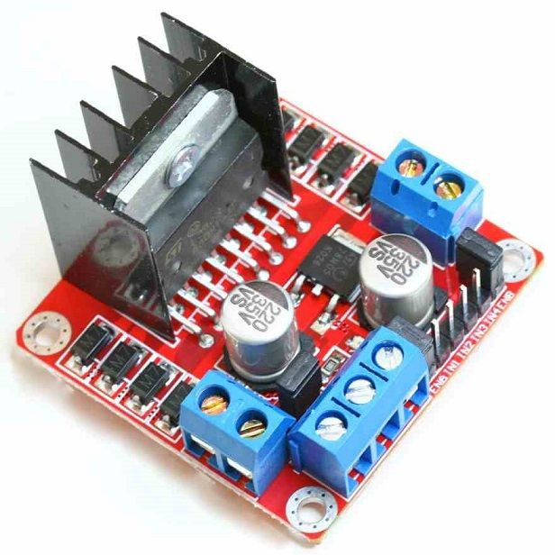
The L298N module can provide the +5V needed by the Arduino as long as its input voltage is +7 V or greater. However, I chose to have separate power sources for the motor and the circuit for isolation. Note that if you are planning to use a supply voltage of more than +12V for the L298N module, you need to remove the jumper just above the +12V input.
Building the Robot
Robot frame (made mostly of acrylic slab) with two geared dc motors
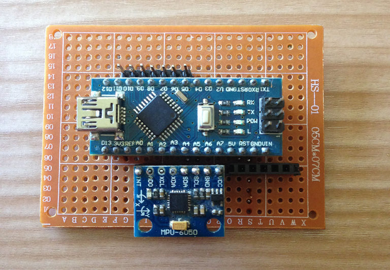
Main circuit board consisting of an Arduino Nano and MPU6050
L298N motor driver module
Geared DC motor with wheel
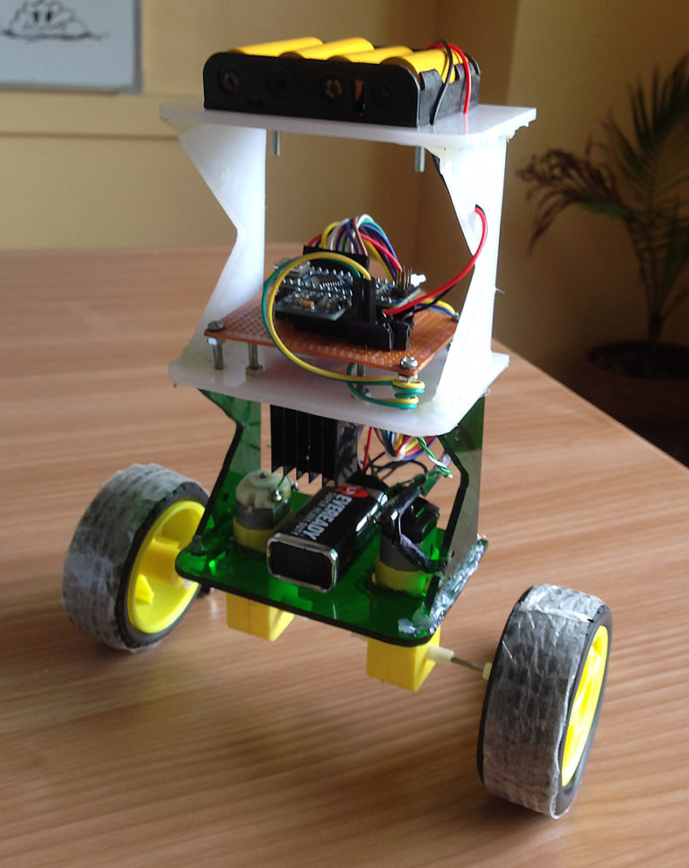
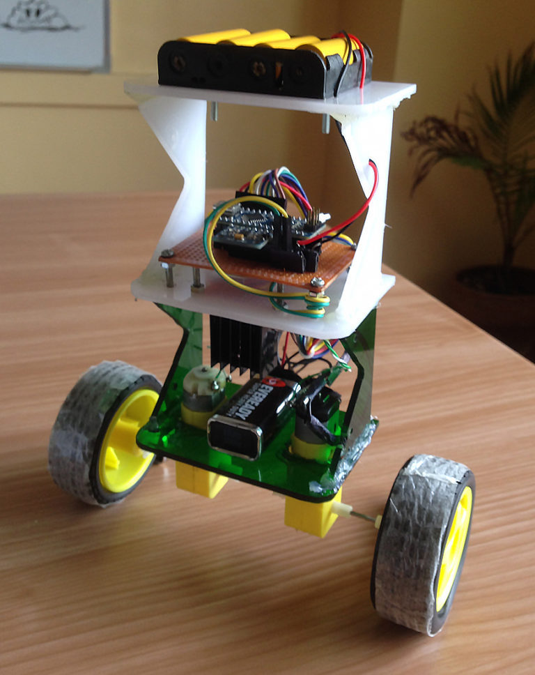
The self-balancing robot is essentially an inverted pendulum. It can be balanced better if the center of mass is higher relative to the wheel axles. A higher center of mass means a higher mass moment of inertia which corresponds to lower angular acceleration (slower fall). This is why I’ve placed the battery pack on top. The height of the robot, however, was chosen based on the availability of materials.
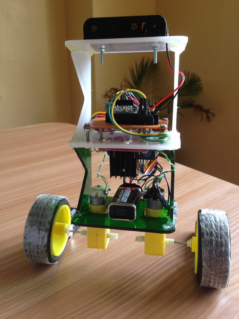
Completed self-balancing robot. At the top are six Ni-Cd batteries for powering the circuit board. In between the motors is a 9V battery for the motor driver.
More Self-balancing Theories
In control theory, keeping some variable (in this case, the position of the robot) steady needs a special controller called a PID: P for proportional, I for integral, and D for derivative. Each of these parameters has “gains” normally called Kp, Ki, and Kd.
PID provides correction between the desired value (or input) and the actual value (or output). The difference between the input and the output is called “error”. The PID controller reduces the error to the smallest value possible by continually adjusting the output. In our Arduino self-balancing robot, the input (which is the desired tilt, in degrees) is set by software. The MPU6050 reads the current tilt of the robot and feeds it to the PID algorithm which performs calculations to control the motor and keep the robot in the upright position.
PID requires that the gains Kp, Ki, and Kd values be “tuned” to optimal values. Engineers use software like MATLAB to compute these values automatically. Unfortunately, we can’t use MATLAB in our case because it would further complicate the project. We will tune the PID values manually instead. I’ve outlined the steps on how to do this:
-
- Make Kp, Ki, and Kd equal to zero.
- Adjust Kp. Too little Kp will make the robot fall over (not enough correction). Too much Kp will make the robot go back and forth wildly. A good enough Kp will make the robot slightly go back and forth (or oscillate a little).
- Once the Kp is set, adjust Kd. A good Kd value will lessen the oscillations until the robot is almost steady. Also, the right amount of Kd will keep the robot standing even if pushed.
- Lastly, set the Ki. The robot will oscillate when turned on even if the Kp and Kd are set but will stabilize in time. The correct Ki value will shorten the time it takes for the robot to stabilize.
Arduino Self-balancing Robot Code
I needed four external libraries to make this Arduino self-balancing robot work. The PID library makes it easy to calculate the P, I, and D values. The LMotorController library is used for driving the two motors with the L298N module. The I2Cdev library and MPU6050_6_Axis_MotionApps20 library are for reading data from the MPU6050. You can download the code including the libraries in this repository.
#include <PID_v1.h>
#include <LMotorController.h>
#include "I2Cdev.h"
#include "MPU6050_6Axis_MotionApps20.h"

#if I2CDEV_IMPLEMENTATION == I2CDEV_ARDUINO_WIRE
 #include "Wire.h"
#endif

#define MIN_ABS_SPEED 20

MPU6050 mpu;

// MPU control/status vars
bool dmpReady = false; // set true if DMP init was successful
uint8_t mpuIntStatus; // holds actual interrupt status byte from MPU
uint8_t devStatus; // return status after each device operation (0 = success, !0 = error)
uint16_t packetSize; // expected DMP packet size (default is 42 bytes)
uint16_t fifoCount; // count of all bytes currently in FIFO
uint8_t fifoBuffer[64]; // FIFO storage buffer

// orientation/motion vars
Quaternion q; // [w, x, y, z] quaternion container
VectorFloat gravity; // [x, y, z] gravity vector
float ypr[3]; // [yaw, pitch, roll] yaw/pitch/roll container and gravity vector

//PID
double originalSetpoint = 173;
double setpoint = originalSetpoint;
double movingAngleOffset = 0.1;
double input, output;

//adjust these values to fit your own design
double Kp = 50;
double Kd = 1.4;
double Ki = 60;
PID pid(&input, &output, &setpoint, Kp, Ki, Kd, DIRECT);

double motorSpeedFactorLeft = 0.6;
double motorSpeedFactorRight = 0.5;
//MOTOR CONTROLLER
int ENA = 5;
int IN1 = 6;
int IN2 = 7;
int IN3 = 8;
int IN4 = 9;
int ENB = 10;
LMotorController motorController(ENA, IN1, IN2, ENB, IN3, IN4, motorSpeedFactorLeft, motorSpeedFactorRight);

volatile bool mpuInterrupt = false; // indicates whether MPU interrupt pin has gone high
void dmpDataReady()
{
 mpuInterrupt = true;
}


void setup()
{
 // join I2C bus (I2Cdev library doesn't do this automatically)
 #if I2CDEV_IMPLEMENTATION == I2CDEV_ARDUINO_WIRE
 Wire.begin();
 TWBR = 24; // 400kHz I2C clock (200kHz if CPU is 8MHz)
 #elif I2CDEV_IMPLEMENTATION == I2CDEV_BUILTIN_FASTWIRE
 Fastwire::setup(400, true);
 #endif

 mpu.initialize();

 devStatus = mpu.dmpInitialize();

 // supply your own gyro offsets here, scaled for min sensitivity
 mpu.setXGyroOffset(220);
 mpu.setYGyroOffset(76);
 mpu.setZGyroOffset(-85);
 mpu.setZAccelOffset(1788); // 1688 factory default for my test chip

 // make sure it worked (returns 0 if so)
 if (devStatus == 0)
 {
 // turn on the DMP, now that it's ready
 mpu.setDMPEnabled(true);

 // enable Arduino interrupt detection
 attachInterrupt(0, dmpDataReady, RISING);
 mpuIntStatus = mpu.getIntStatus();

 // set our DMP Ready flag so the main loop() function knows it's okay to use it
 dmpReady = true;

 // get expected DMP packet size for later comparison
 packetSize = mpu.dmpGetFIFOPacketSize();

 //setup PID
 pid.SetMode(AUTOMATIC);
 pid.SetSampleTime(10);
 pid.SetOutputLimits(-255, 255);
 }
 else
 {
 // ERROR!
 // 1 = initial memory load failed
 // 2 = DMP configuration updates failed
 // (if it's going to break, usually the code will be 1)
 Serial.print(F("DMP Initialization failed (code "));
 Serial.print(devStatus);
 Serial.println(F(")"));
 }
}


void loop()
{
 // if programming failed, don't try to do anything
 if (!dmpReady) return;

 // wait for MPU interrupt or extra packet(s) available
 while (!mpuInterrupt && fifoCount < packetSize)
 {
 //no mpu data - performing PID calculations and output to motors
 pid.Compute();
 motorController.move(output, MIN_ABS_SPEED);

 }

 // reset interrupt flag and get INT_STATUS byte
 mpuInterrupt = false;
 mpuIntStatus = mpu.getIntStatus();

 // get current FIFO count
 fifoCount = mpu.getFIFOCount();

 // check for overflow (this should never happen unless our code is too inefficient)
 if ((mpuIntStatus & 0x10) || fifoCount == 1024)
 {
 // reset so we can continue cleanly
 mpu.resetFIFO();
 Serial.println(F("FIFO overflow!"));

 // otherwise, check for DMP data ready interrupt (this should happen frequently)
 }
 else if (mpuIntStatus & 0x02)
 {
 // wait for correct available data length, should be a VERY short wait
 while (fifoCount < packetSize) fifoCount = mpu.getFIFOCount();

 // read a packet from FIFO
 mpu.getFIFOBytes(fifoBuffer, packetSize);

 // track FIFO count here in case there is > 1 packet available
 // (this lets us immediately read more without waiting for an interrupt)
 fifoCount -= packetSize;

 mpu.dmpGetQuaternion(&q, fifoBuffer);
 mpu.dmpGetGravity(&gravity, &q);
 mpu.dmpGetYawPitchRoll(ypr, &q, &gravity);
 input = ypr[1] * 180/M_PI + 180;
 }
}
My Kp, Ki, Kd values may or may not work you. If it doesn’t, then follow the steps I outlined above. Notice that the input tilt in my code is set to 173 degrees. You can change this value if you’d like but take note that this is the tilt angle to which the robot must be maintained.
Also, if your motors are too fast, you can adjust the motorSpeedFactorLeft and motorSpeedFactorRight values.
Video
Here’s the self-balancing robot in action!
What’s Next?
An improvement for this self-balancing robot would be controlling it remotely. Unfortunately, I can’t make this robot do that unless I make it ultra stable using dc motors with an encoder. An encoder would update the current speed of the motor which I can use to make the robot steadier via a second PID loop. I might do that next time so stay tuned!
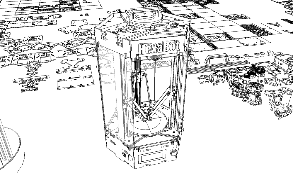
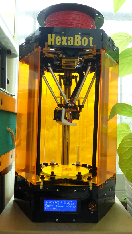
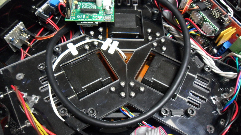
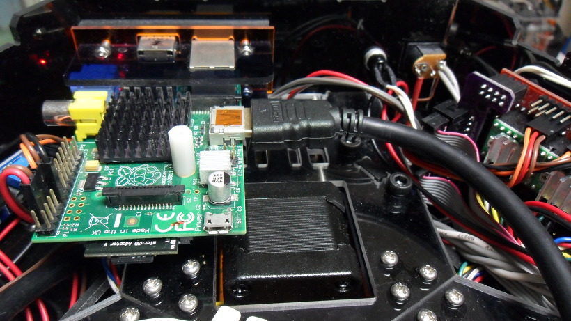
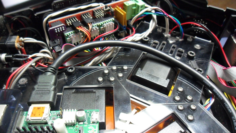
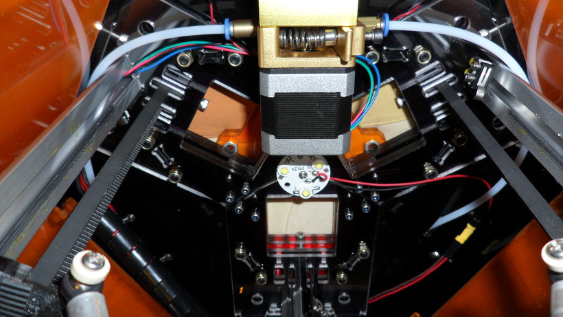
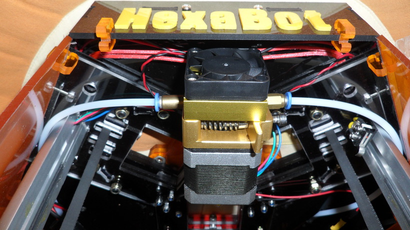
DIY Delta 3D Printer – HexaBot
DIY Delta 3D Printer – HexaBot
3D Design Tool: SketchUp Pro
Technical Specifications
Printing
Technology: FFF(Fused Filament Fabrication) / Delta
Build Volume: 95 (W) x 95 (D) x 135 (H) mm
- Auto running Heatbed
Layer Resolution: 50-200 microns
Filament: ABS or PLA, Nyron, HIPS, PVA… 1.75 mm diameter
Nozzle Diameter: 0.4 mm (0.2mm, 0.3mm, 0.8mm)
Print File Type: .Gcode, .STL
Layer Resolutions: - Fast: 200 micron (0.2 mm)
- Normal: 100 micron (0.1 mm)
- hHigh: 0.06 micron (0.06 mm)
- Ultra High: 0,04 micron (0.04 mm)
Size and Weight
Product Dimensions: 260 (W) x 300 (D) x 460 (H) mm
Product Weight: 4.5 kg
Software
Software Bundle: Cura, Slic3r, KISSlicer / Octoprint, Printrun, Repetier-Host, MatterControl
Supported File Types: .STL, .OBJ, .AMF, .Gcode
Operating Systems: All (Web-based): Windows, Mac OS, Linux
Firmware
Arduino: Modified Marlin v1.0.0
Raspberry Pi: Rasbian, Octoprint, SSH, Samba, VNC, WiringPi
Hardware
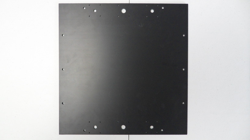
Base Plate: Profile DRF 2020, Acrylic
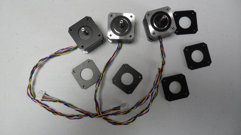
Step Motor: NEMA 17 – Phase: 4, Step Angle: 1.8 Deg/Step, Holding Torque: 2.6Kg.cm
- X/Y/Z/E – 4EA
Cartesian (xyz): X/Y Head: LM Guide, Z Bed: 10mm Linear Shaft and 8D Screw Rod
Electrical
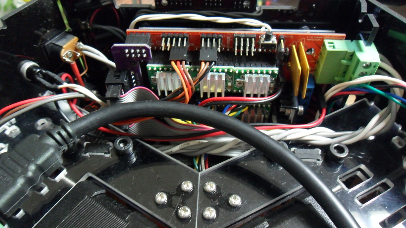
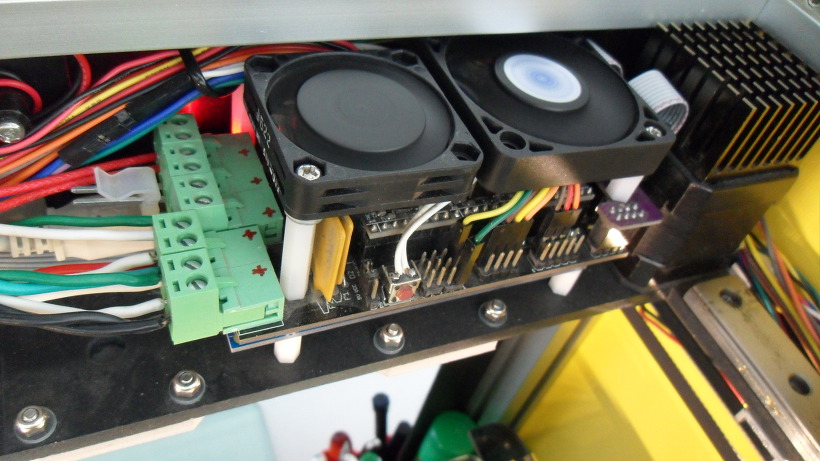
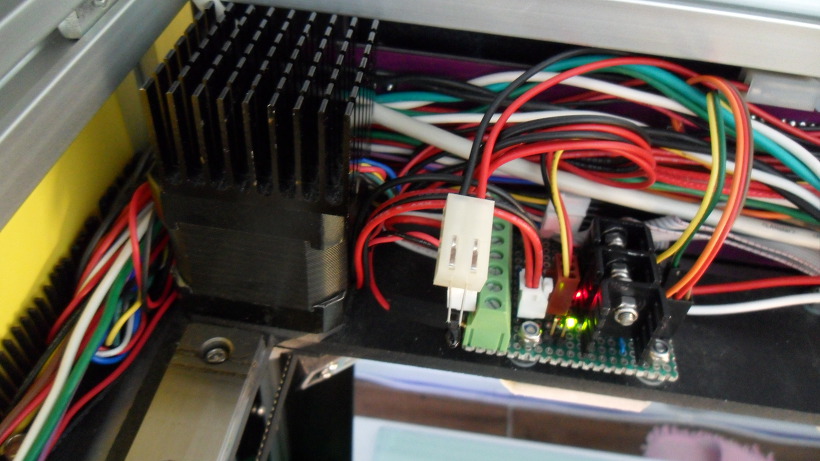
Control Board: Arduino Mega 2560
Control Shield: Ramps 1.4 Board
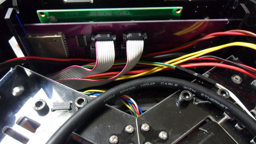
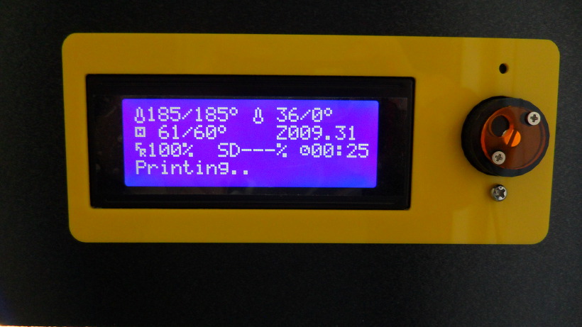
Display Board: Reprap Discount Smart Controller LCD 2004
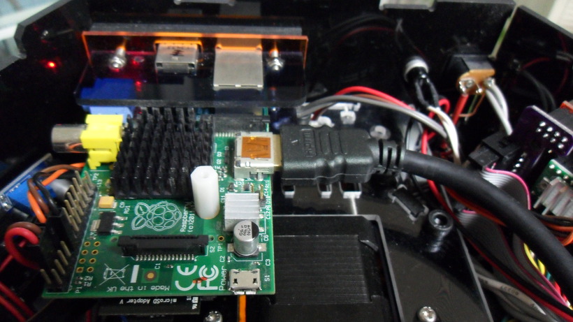
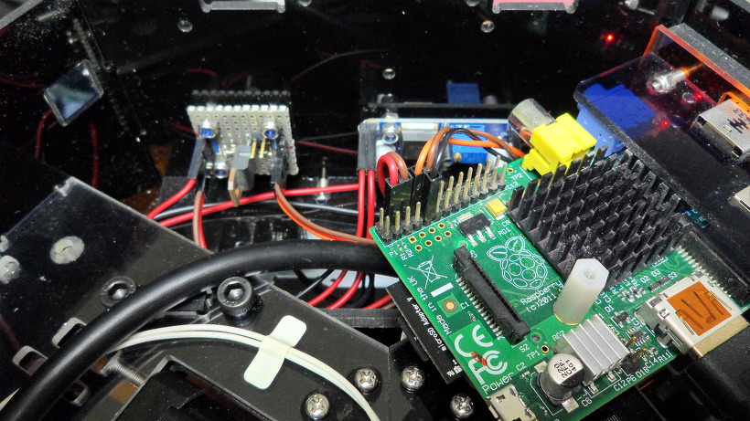
Raspberry Pi: Raspberry Pi B
Power Requirements: AC 100 – 240 V, 50-60 Hz, 12 VDC, 4.5A, 54 W
Connectivity: USB, SD Card, Wi-Fi (Web-based)
Temperature: - Nozzle temperature: 170 – 270
- Heated bed temperature: 50 – 100
- Operational temperature: 10 – 40
- Storage temperature: 0 – 32
https://www.thingiverse.com/thing:917729
Thanks for watching!…….coming soon!……Updating……
The open source HexaBot hardware and software is free and made with love. Please show your level of support with a voluntary donation.
Donate:
https://www.paypal.com/cgi-bin/webscr?cmd=_s-xclick&hosted_button_id=RDN7ZGAVFS5UE
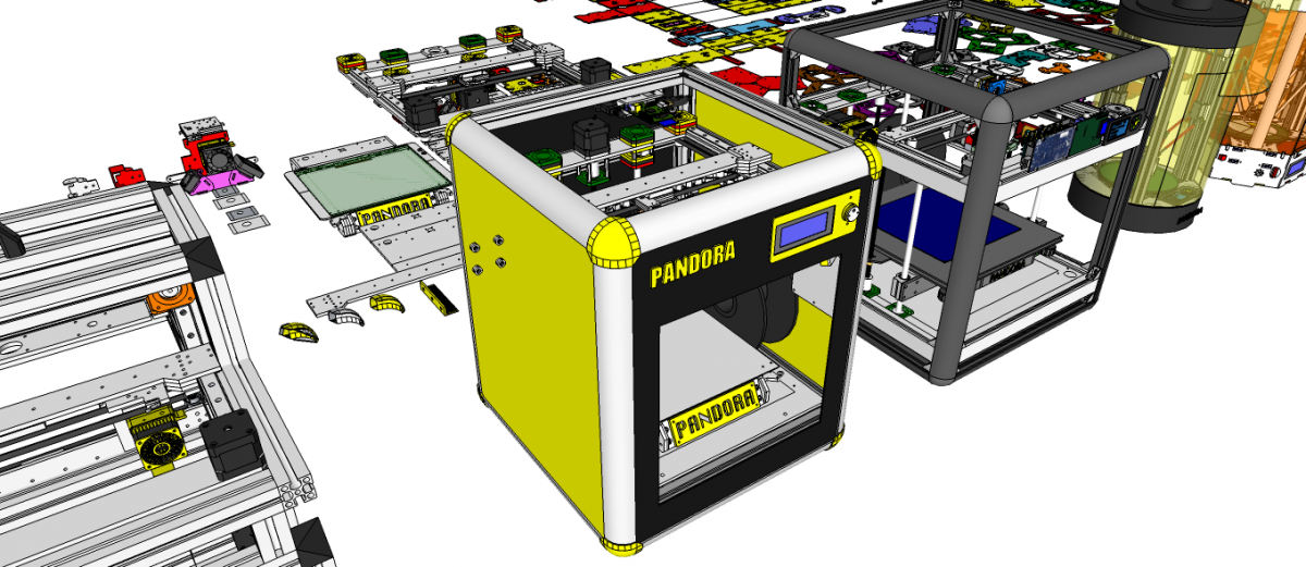
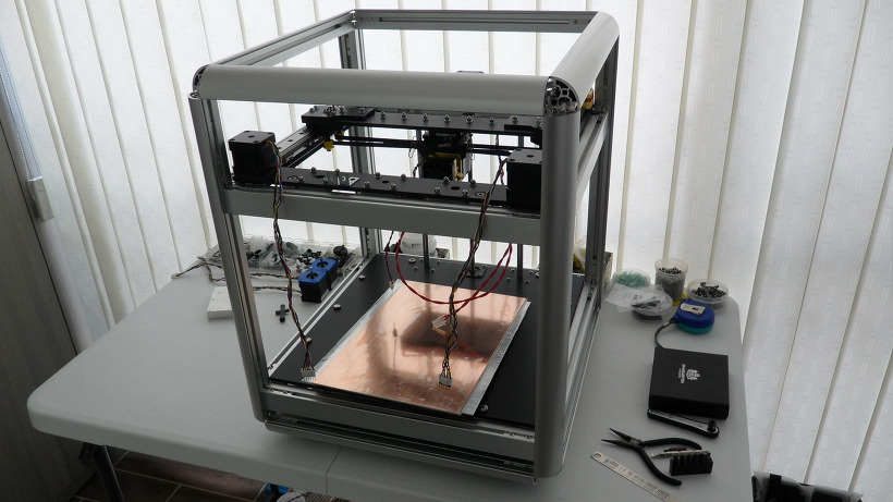
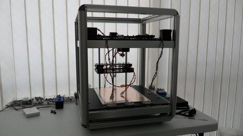
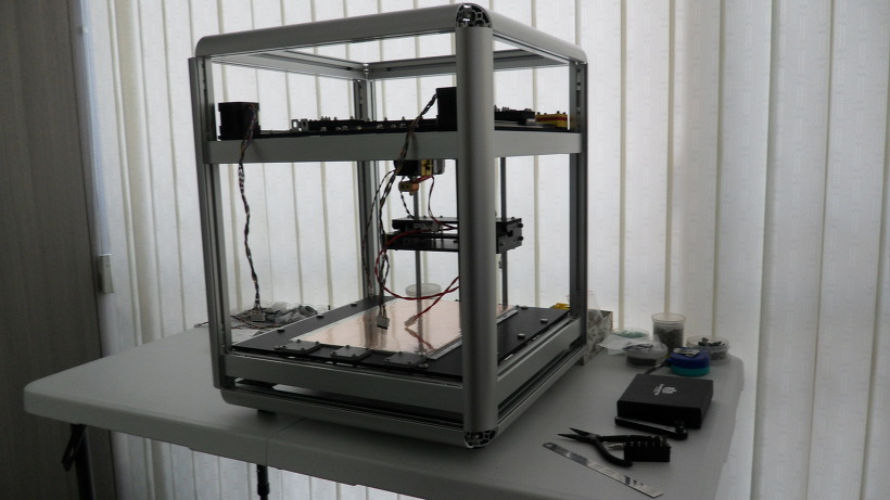
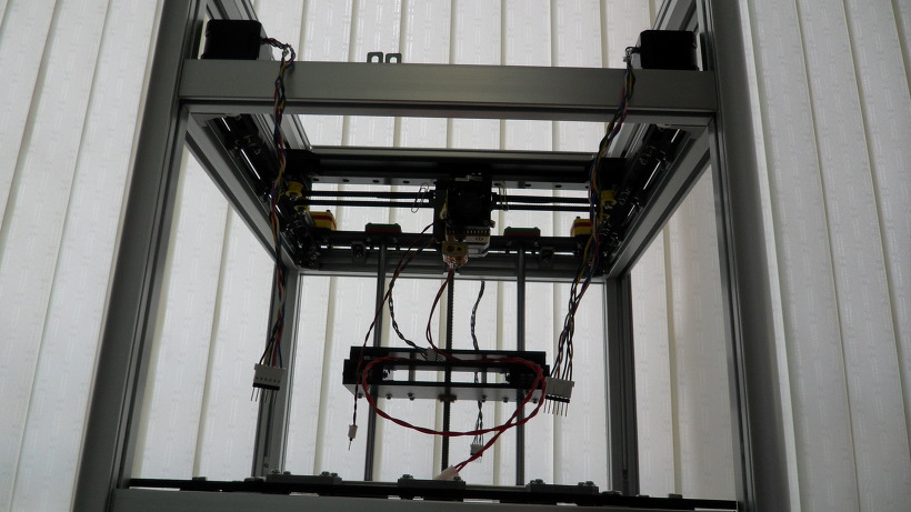
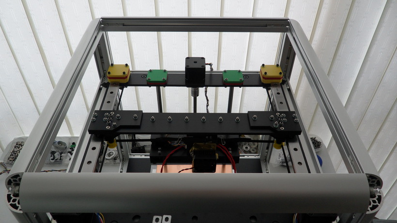
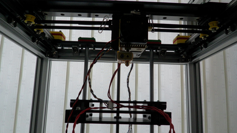
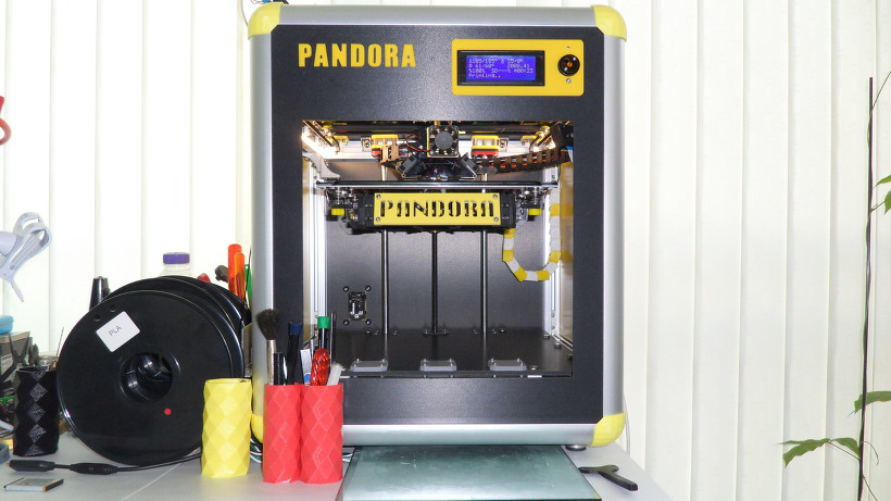
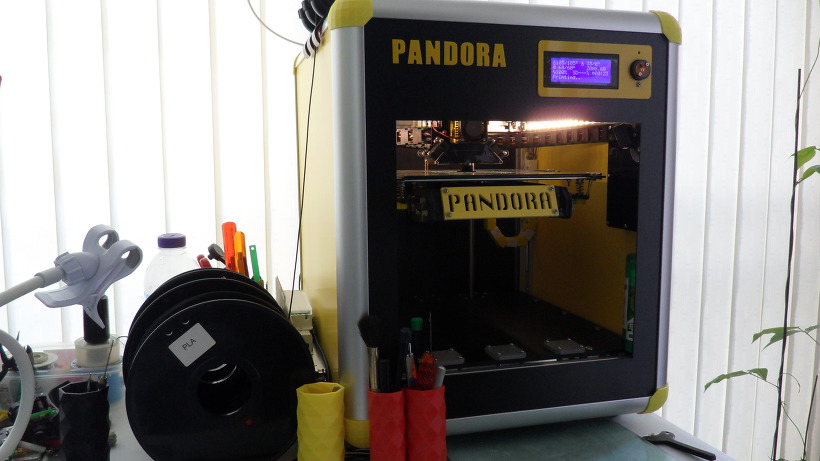
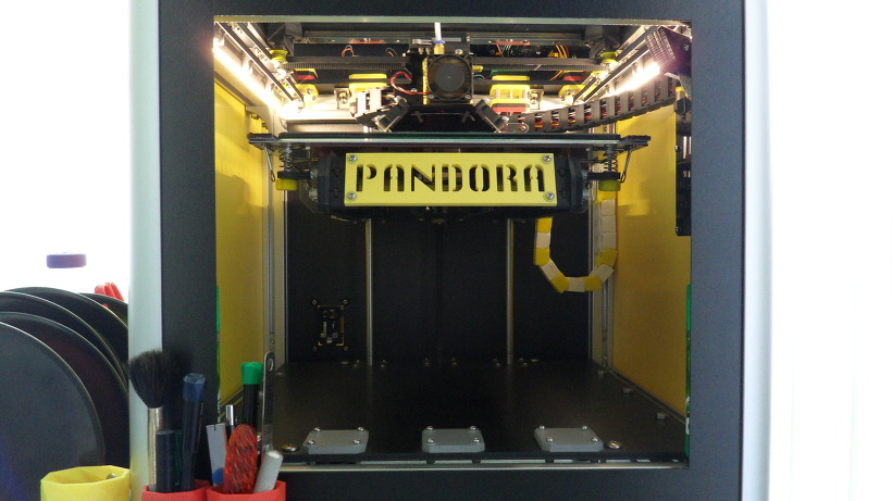
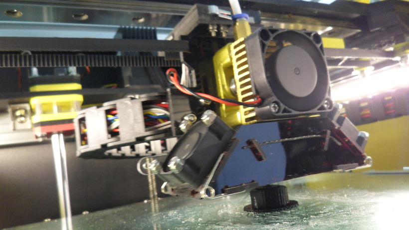
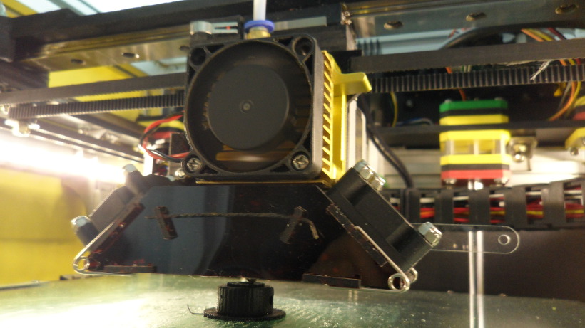
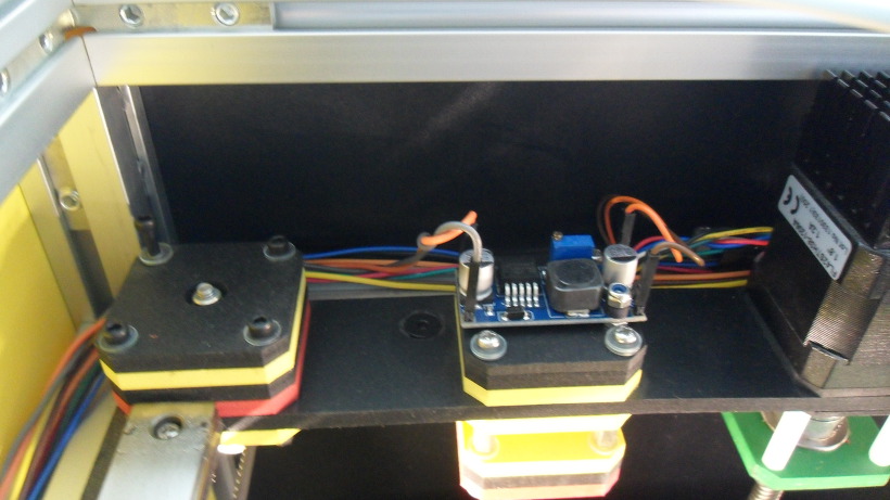
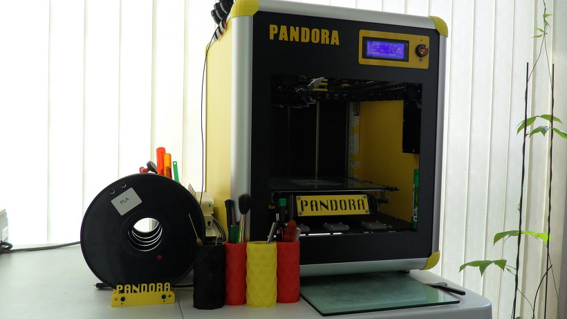
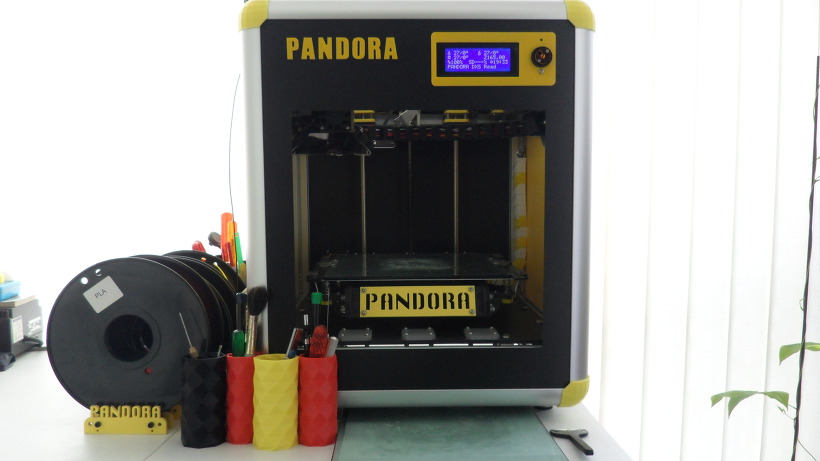
DIY 3D Printer PANDORA DXs
DIY 3D Printer – PANDORA DXs (Design eXtreme single)
3D Design Tool: SketchUp Pro
Technical Specifications
Printing
Technology: FFF(Fused Filament Fabrication) / H-Bot(CoreXY)
Build Volume: 223 (W) x 225 (D) x 165 (H) mm
- Heatbed
Layer Resolution: 50-200 microns
Filament: ABS or PLA, Nyron, HIPS, PVA… 1.75 mm diameter
Nozzle Diameter: 0.4 mm (0.2mm, 0.3mm, 0.8mm)
Print File Type: .Gcode, .STL
Layer Resolutions: - Fast: 200 micron (0.2 mm)
- Normal: 100 micron (0.1 mm)
- hHigh: 0.06 micron (0.06 mm)
- Ultra High: 0,04 micron (0.04 mm)
Size and Weight
Product Dimensions: 426 (W) x 433 (D) x 500 (H) mm
Product Weight: 11 kg
Software
Software Bundle: Cura, Slic3r, KISSlicer / Octoprint, Printrun, Repetier-Host, MatterControl
Supported File Types: .STL, .OBJ, .AMF, .Gcode
Operating Systems: All (Web-based): Windows, Mac OS, Linux
Firmware
Arduino: Modified Marlin v1.0.0
Raspberry Pi: Rasbian, Octoprint, SSH, Samba, VNC, WiringPi
Hardware
Base Plate: Profile DRF 3030, Acrylic
Step Motor: NEMA 17 – Phase: 4, Step Angle: 1.8 Deg/Step, Holding Torque: 2.6Kg.cm - X/Y/Z/E – 4EA
Cartesian (xyz): X/Y Head: LM Guide, Z Bed: 10mm Linear Shaft and 8D Screw Rod
Electrical
Control Board: Arduino Mega 2560
Control Shield: Ramps 1.4 Board
Display Board: Reprap Discount Smart Controller LCD 2004
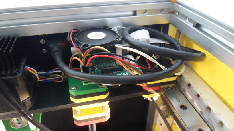
Raspberry Pi: Raspberry Pi B
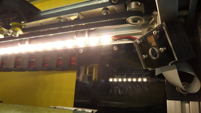
Camera: Raspberry Camera
Power Requirements: AC 100 – 240 V, 1.4 Amps, 50-60 Hz, 220 W
Connectivity: USB, SD Card, Wi-Fi (Web-based)
Temperature: - Nozzle temperature: 170 – 270
- Heated bed temperature: 50 – 100
- Operational temperature: 10 – 40
- Storage temperature: 0 – 32
https://www.thingiverse.com/thing:917718
Thanks for watching!……..Coming soon!……..Updating……
The open source PANDORA DXs hardware and software is free and made with love. Please show your level of support with a voluntary donation.
Donate:
https://www.paypal.com/cgi-bin/webscr?cmd=_s-xclick&hosted_button_id=RDN7ZGAVFS5UE

