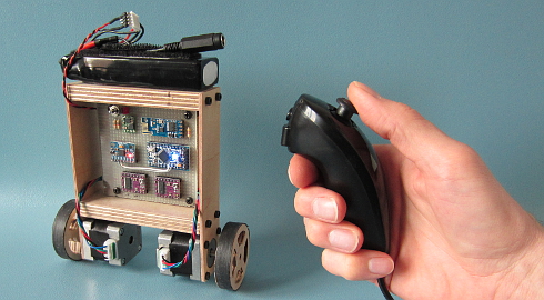
Your Arduino Balancing Robot (YABR) is a self-balancing robot that you can build yourself as a school project or as a fun project with your kids. It might look simple but there is a lot that you can learn from building this self-balancing robot.
In contrast to most self-balancing robots, this one uses stepper motors instead of regular DC motors. The main reason is that stepper motors are precise and have no performance loss when the battery voltage drops. One pulse is always an exact amount of motion. Regular DC motors can have mechanical friction and electric resistance differences. This can cause performance differences. As a result the robot will not move in a straight line.
The total cost to build this robot is approximately $80 if you use the hardware list below. This includes a battery, Nunchuck, charger, stepper motors, etc.
The Arduino program that you can download for free is 100% self-written and not based on any other software. The code is well commented and clearly explained. This makes it possible to further develop the code for your own purpose.
If you encounter any problems during the build or setup please check the  Q&A page first. Most questions are already answered in detail.
Step 1 – Software
First download the complete YMFC-AL software package:
Step 2 – Hardware
To build this robot you need hardware. I made the following list for convenience purpose alone. You are free to get your own hardware from different sources. But this is the hardware that I used/ordered:
- 1 x Arduino pro mini clone
- 1 x FTDI USB to TTL programmer for the Arduino pro mini
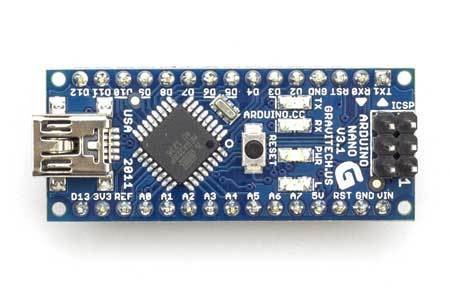
- 1 x Arduino Uno clone
- 1 x MPU-6050 gyro and accelerometer
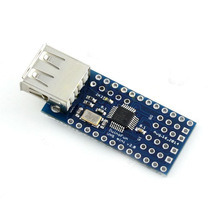
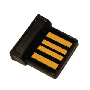
- 2 x 2.4G wireless serial transceiver module
- 2 x 35mm Stepper motor
- 2 x Geeetech StepStick DRV8825
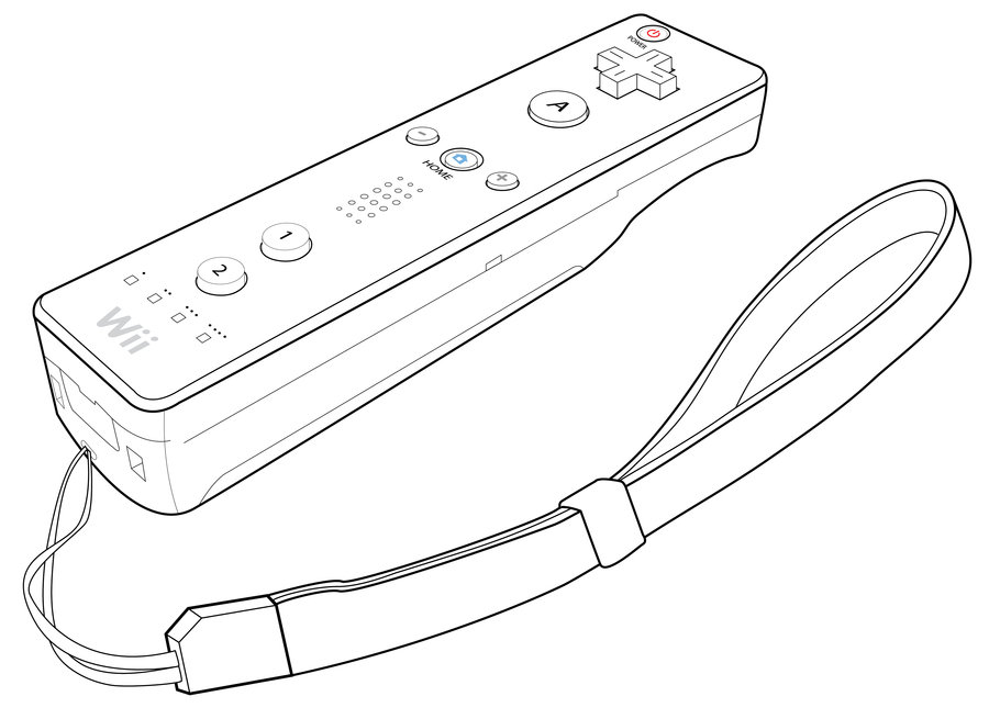
- 1 x Wired nunchuck controller for Wii
- 1 x Mini DC 7~28V to DC 5V step-down converter
- 1 x 11.1V 2200mAh 30C Li-polymer Battery
- 1 x B3AC 2S/3S Lipo balance charger
If the 35mm stepper motors are out of stock. You could also use these stepper motors. Please note that these are 42mm in stead of 35mm. So you have to modify the frame.
Most of the following parts can be found in your local electronics store. But in case you don’t have an electronics store nearby I will put links here:
- 1 x 1/4W Ceramic metal film resistors set (600 PCS)
- 1 x Glass fiber prototyping PCB
- 1 x 3-Pin toggle switch (5-Pack)
And finally you need an old inner tube and two sheets of plywood. I used 2.5mm and 12.5mm sheets.
Step 3 – Tools
And of course you need some simple tools like a soldering iron, screwdrivers, a fretsaw, compact drill, etc.
Step 4 – The build
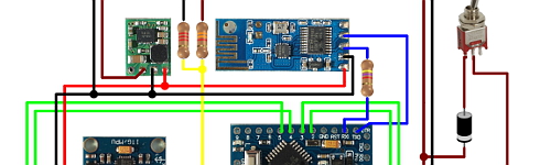
Watch the YABR hardware build video and build the robot according to the video and the schematic that is included in the complete software package.
| Building the YABR balancing robot. |
Detailed pictures of my own YABR balancing robot can be found in the media section of this project page.
4.1 The diode and resistors
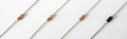
The resistor R1 on the schematic is needed for uploading a program to the Arduino. The TXD output of the transceiver is forced high or low. As a result the FTDI programmer cannot change this output anymore and you will get an upload error. By adding this resistor the FTDI programmer can change the voltage on the RX-pin of the Arduino despite the state the transceiver output and the program is uploaded without any problems.
The other two resistors (R2 and R3) form a voltage divider. Meaning that the 12.6 volt of the battery minus the 0.6 volt voltage drop over the diode is divided by 2.5. Resulting in a 4.8 volt on the analog input when the battery fully charged. In the main program this analog input will be used to protect the battery. This is because lipo batteries can be damaged when the voltage drops below 3 volt per cell.
The diode D1 protects all the electronics against reversed polarity. So when you accidentally reverse the connections of the battery the components won’t go up in smoke.
4.2 The MPU-6050 gyro/accelerometer
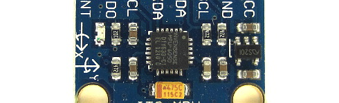
The only gyro / accelerometer that is supported by the YABR software is the MPU-6050. This is because the self-level feature requires an accelerometer and a gyro as I explain in these two videos:
| MPU-6050 6dof IMU tutorial for auto-leveling quadcopters – Part 1 |
| MPU-6050 6dof IMU tutorial for auto-leveling quadcopters – Part 2 |
The orientation of the gyro is important. Make sure to mount the gyro in the exact same orientation as shown on this picture. Otherwise the YABR software cannot calculate the correct angle and the robot will not work.
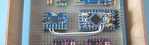
4.3 Hardware test
Please note that you are soldering the wires on the back side of the PCB. The schematic is drawn facing the components from the front. So everything is mirrored and you need to double check all the connections before you connect any power to the PCB.
With everything in place it’s time to connect the FTDI programmer to the Arduino pro mini. Don’t connect the battery yet. If the LED’s don’t lit up there is a short circuit in the wiring and you need to disconnect the FTDI programmer as soon as possible. Normally the Arduino pro mini is already programmed with the blink sketch so the LED on the Arduino should start to flash.
To check if the gyro is connected correctly and to check the balancing point of the robot you need to upload the “hardware-check” program that you can find in the software package that you downloaded earlier.

Test the balancing angle of the robot and fix it in that position on a stand as I showed in the video. Upload the “hardware-check” program, open the serial monitor and set the baud rate to 9600.
After uploading the program, open the serial monitor and set the baud rate to 9600.
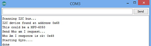
The program will check if there is any I2C device is connected and if this is a MPU-6050. If everything is working as expected the program will output several raw gyro values on the screen. These are just examples and your values may be different. Note down the balance value that you see in the serial output. You will need it later in the main program.
4.4 Limit the motor current
Next thing on the to do list is to set the stepper controllers to the correct drive current. If the motor current is set to high the stepper controllers will heat up and they might get damaged.
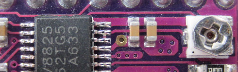
First set the potentiometer at the same position as shown in the picture below. Now always be careful when connecting the lipo battery for the first time. A short circuit can cause high currents, heat, sparks, and burns.
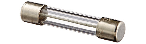
A good alternative is to use a small DC fuse like the one below. This fuse will blow if the wiring on the back side of the pcb holds a short circuit.
The easiest and safest way to set the correct current and to check if the wiring is correctly connected is by measuring the current in the power supply wires with a bench power supply. The power supply is limited to 500milli amps. This is an extra safety feature. If there is a short circuit the power supply will limit the current to 500 milli amps and the wiring will be fine.
First connect one motor. With the potentiometer it’s possible to set the current between 100 and 150mA. This is more than enough to get good performance. Do the same with the other stepper controller.
If you don’t have the possibility to measure the current just set the potentiometer in this position and feel if the stepper driver doesn’t get to hot. But it’s always best to measure the current.
3.5 The remote control
If you open the Nunchuck you can note the wire colors that are connected to the various pins as you can see on the schematic. The Nunchuck works on 3.3V and you can use the 3.3V output of the Arduino Uno to power the Nunchuck.
The 5V output can be used for the transceiver. Again, connect the wires as shown on the schematic to get it to work.
To check if the Nunchuck is connected correctly you need to upload the “hardware-check” program that you can find in the software package that you downloaded earlier. After uploading the program, open the serial monitor and set the baud rate to 9600.
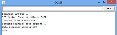
The program will check if there is any I2C device is connected and if this is a Nunchuck. If everything is working as expected the program will output several raw joystick values on the screen.
Step 5 – Upload the software
And finally you can upload the YABR-remote program to the Arduino Uno and the YABR-robot program to the Arduino pro mini.
The YABR-remote program does not need any modification. In the robot program you need to change the accelerometer calibration value to the value that was shown by the hardware test program when the robot was in it’s balancing position.
To start the robot you need to power up the remote. Lay the robot on it’s back and switch on the power. The LED will blink indicating that the gyro is calibrating. When the blinking stops you can slowly lift the robot and it will automatically start to balance itself.
And basically that’s it. You can now control the robot with the Nunchuck.