THE B-ROBOT EVO (the self balancing robot)

 How does it work?

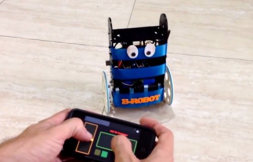
B-ROBOT is a remotely controlled self balancing arduino robot created with 3D printed parts. With only two wheels, B-ROBOT is able to maintain its balance all the time by using his internal sensors and driving the motors. You can control your Robot, making him move or spin,  by sending commands via a Smartphone, Tablet or PC while it maintains its balance.

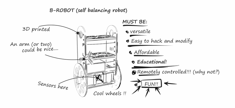
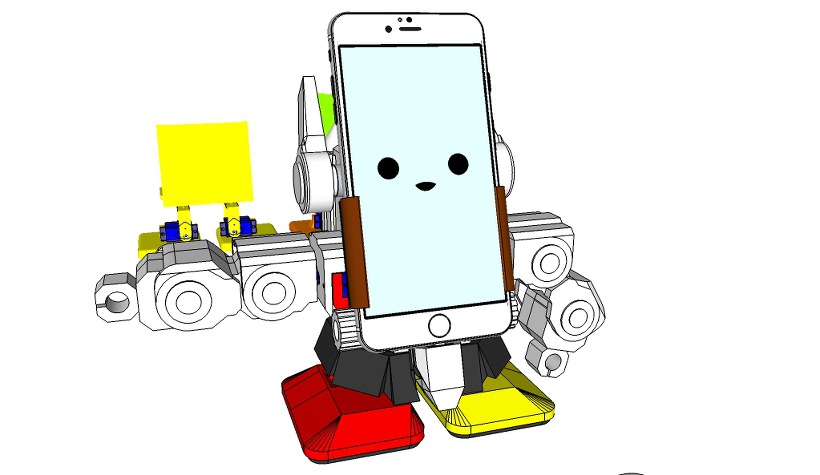
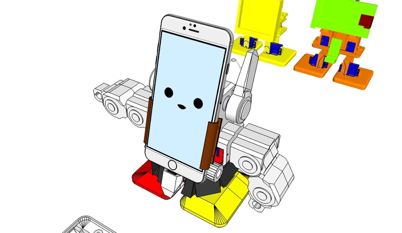
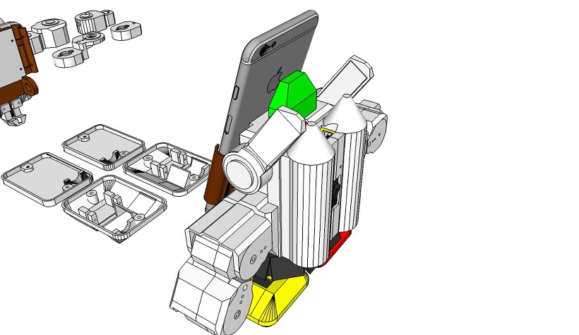
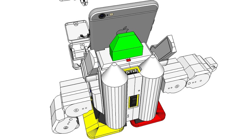
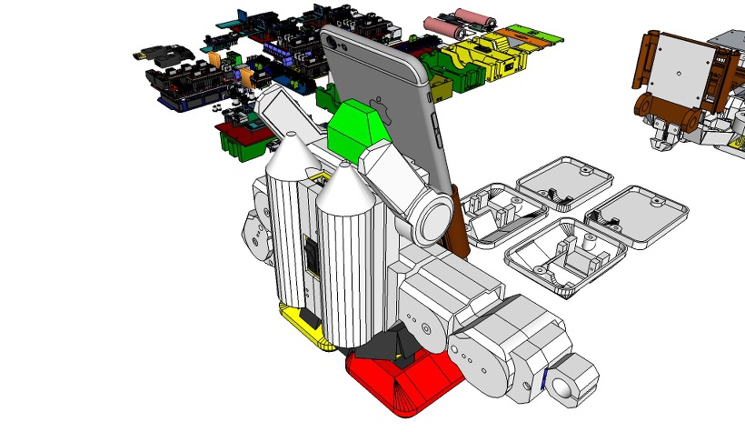
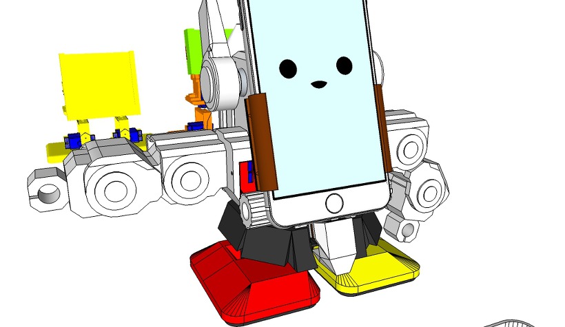
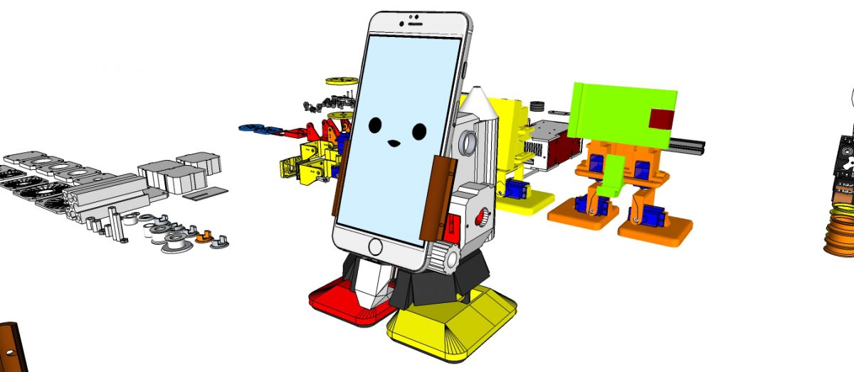
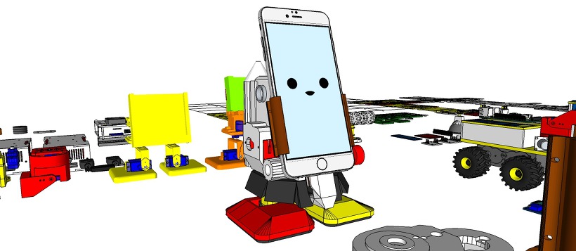
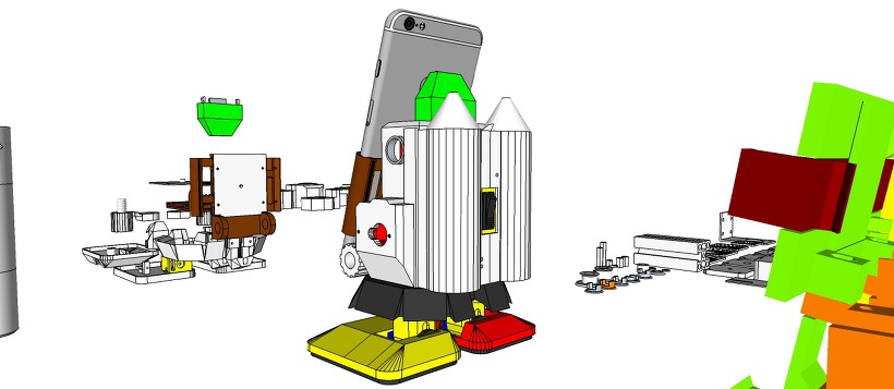
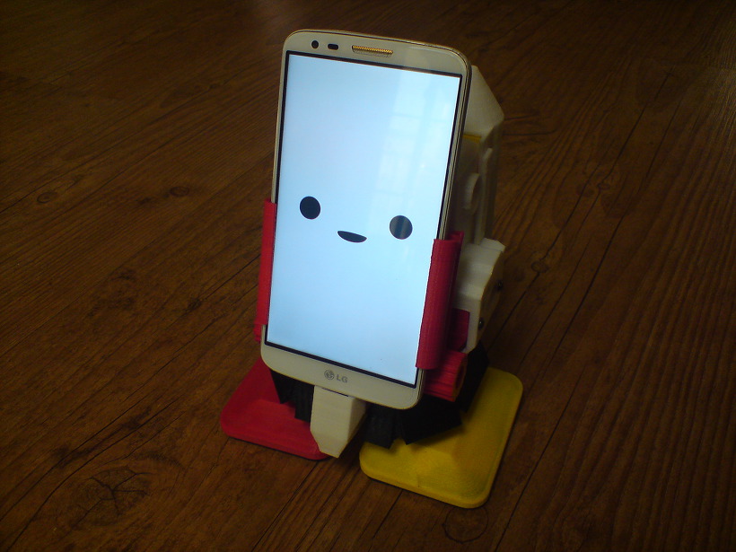
Above: the B-Robot “brainstorming” creation ideas

This self balancing robot reads his inertial sensors (accelerometers and gyroscopes integrated on the MPU6000 chip) 200 times per second. He calculates his attitude (angle with respect to the horizon) and compares this angle with the target angle (0º if he wants to maintain balance without moving, or a positive or negative angle if he wants to move forward or backwards). Using the difference between the target angle (let’s say 0º) and actual angle (let’s say 3º) he drives a Control System to send the right commands to the motors to maintain his balance. The commands to the motors are accelerations. For example if the robot is tilted forward (angle of robot is 3º)then he sends a command to the motors to accelerate forward until this angle is reduced to zero to preserve the balance.

image02

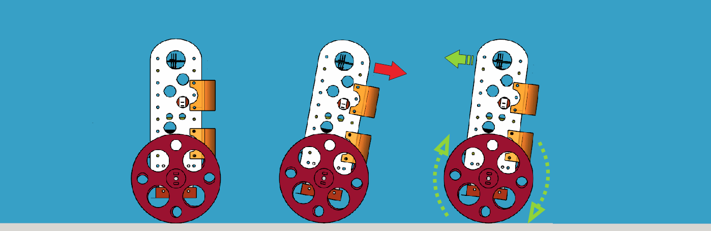
Stable position                  leaning forward                    Correcting its tilt using motors

A bit more in depth…

The physical problem that B-ROBOT solves is called the Inverted Pendulum. This is the same mechanism you need to balance an umbrella above your hand. The pivot point is under the center of mass of the object. More information on Inverted Pendulum here. The mathematical solution to the problem is not easy but we don’t need to understand it in order to solve our robot´s balance issue. What we need to know is how should do to restore the robot´s balance so we can implement a Control Algorithm to resolve the problem.
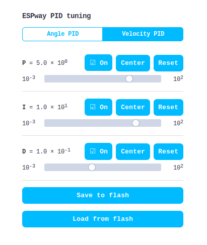
Control System is very useful in Robotics (an Industrial automation). Basically it´s a code that receives information from sensors and target commands as inputs and creates, in consequence, output signals to drive the Robot actuators (the motors in our example) in order to regulate the system. We are using a PID controller (Proportional + Derivative + Integral). This type of control has 3 constants to adjust kP,kD,kI.

 From Wikipedia: “A PID controller calculates an ‘error’ value as the difference between a measured [Input] and a desired setpoint. The controller attempts to minimize the error by adjusting [an Output].”

 So, you tell the PID what to measure (the “Input”) ,where you want that measurement to be (the “Setpoint”,) and the variable you wish to adjust to make that happen (the “Output”.) The PID then adjusts the output trying to make the input equal the setpoint.

For reference, a water tank we want to fill up to a level, the Input, Setpoint, and Output would be the level according to the water level sensor, the desired water level and the water pumped into the tank.


kP is the Proportional part and is the main part of the control, this part is proportional to the error. kD is the Derivative part and is applied to the derivative of the error. This part depends on the dynamics of the system (depends on the robot,´s weight motors, inertias…). The last one, kI is applied to the integral of the error and is used to reduce steady errors, it is like a trim on the final output (think in the trim buttons on an RC car steering wheel to make the car go totally straight, kI removes the offset between the target required and the actual value).

More information on PID controller here.

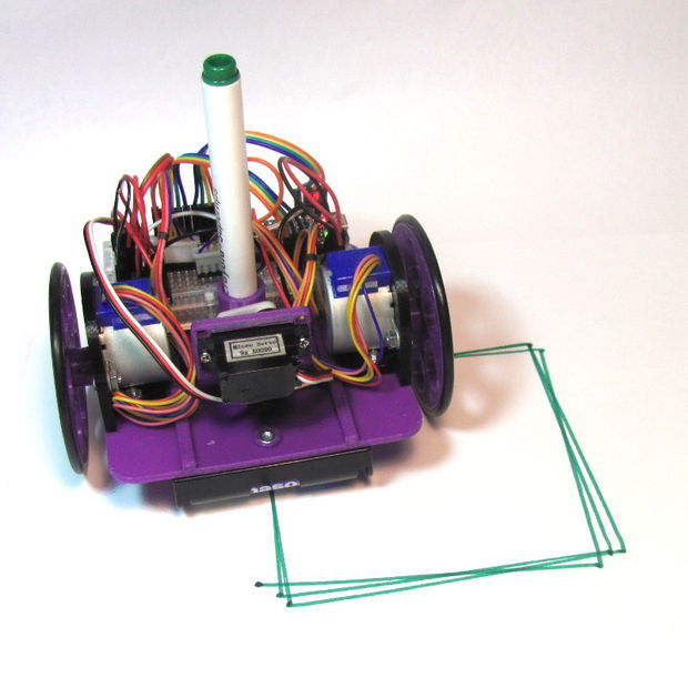
On B-ROBOT the steering command from the user is added to the motors output (one motor with a positive sign and the other with a negative sign). For example if the user sends the steering command 6 to turn to the right (from -10 to 10) we need to add 6 to the left motor value and subtract 6 from the right motor. If the robot is not moving forward or backwards, the result of the steering command is a spin of the robot.

image01

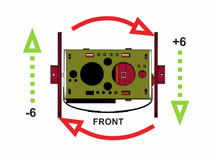
Above: Top view of the B-ROBOT and the commands to the motors


What about the user control?

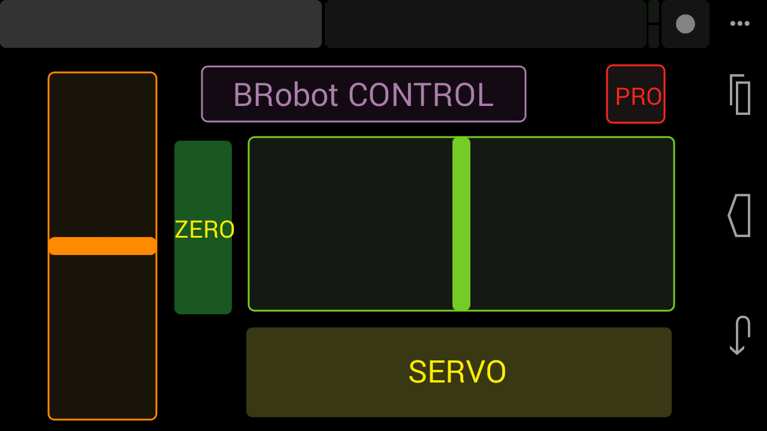
NEW: (Android devices) control your B-robot using the JJrobots FREE APP! 
logo GOOGLE PLAY v2

We have developed an APP for Android users that simplifies the control of the B-robot EVO.

NEW: adjust the stability and behaviour of the B-robot in real time from the PID control APP (free)

More info in the assembly guide page

NEW: (iOS devices)

B-robot control APP (thanks to Xuyen for this great contribution!)


We wanted B-ROBOT to be controlled by the user from almost any existing device, but we don´t want 😉 to develop a lot of  different interfaces for different systems (Android, IOS, PC-windows…). Moreover, we decided to use existing (and powerful) protocols to control “things” and we found (some years ago) a protocol called OSC (Open Sound Control, more info here) used to control musical instruments like synthesizers. Very visual and powerful (we can display  volume control, equalizers, lights…and create our own). To remotely control B-robot, we use OSC protocol over an Internet connection (Wifi module) using UDP packets. This is a lightweight and efficient way to send commands to our Robots!. We could also  personalize the Interface we are using in our device so we will be able to control anything! (well…almost) What we need to do is to implement a lightweight library for Arduino in order to support this protocol (easy). We only use a subset of the OSC protocol to keep things small.

image04 v2
OSC interface on an Android Device.
animacion-test-para-Brobot
controlling the B-ROBOT (the old version in this case)


More about the Control System…

But things are a bit more complex… We have really two PID controllers in a cascade configuration (the output of one controller connected to the next one). The output controller is a speed controller and the inner controller is the stability controller.

BROBOT_control1

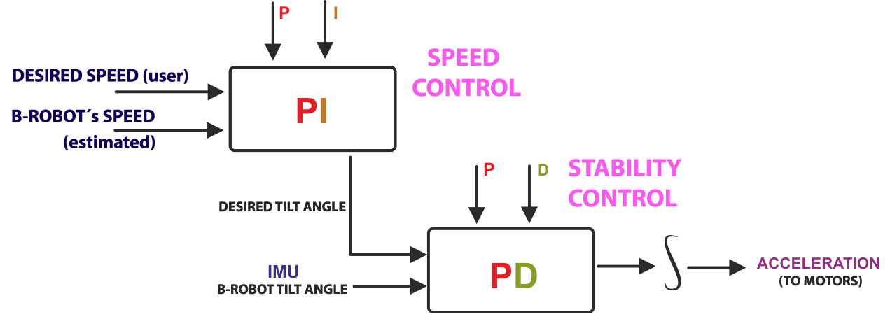
ABOVE: B-ROBOT  control algorithm loop


We could use only one stability controller (the second one) but this would mean that the control´s output would be the desired robot tilt angle, so the user would control the robot angle directly. The problem is that if the center of gravity is not perfectly located above the wheels axis , so the robot needs a little tilt angle to keep the balance and if the user sends a command of tilt=0 then the robot will maintain its balance whilst moving… When adding the second controller (speed controller) the system compensates automatically for this. The user sends a command to the robot speed=0 and this controller will send the “correct” tilt angle to the second controller (stability controller) to mantain the robot balanced and not moving! For the users it is much simpler to set the desired robot speed and the system will find the right robot angle to achieve this speed.


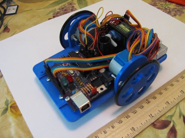
Now… How to create a self balancing robot like B-robot


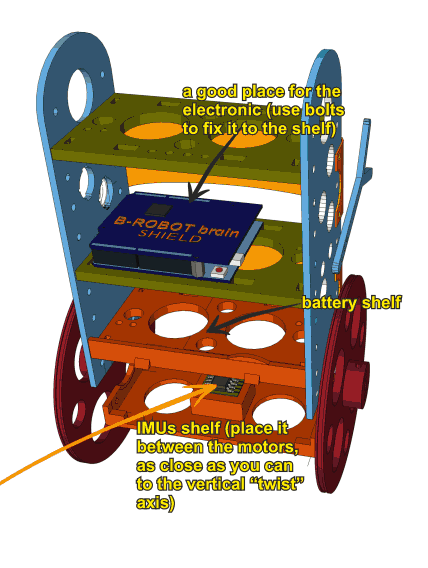
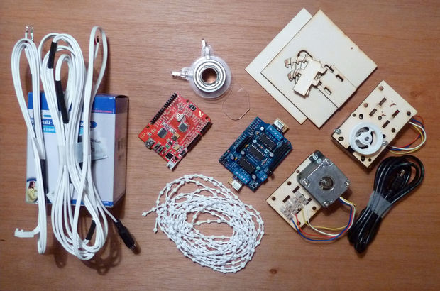
To create a B-ROBOT, you will need:

  1. B-ROBOT electronic brain shield
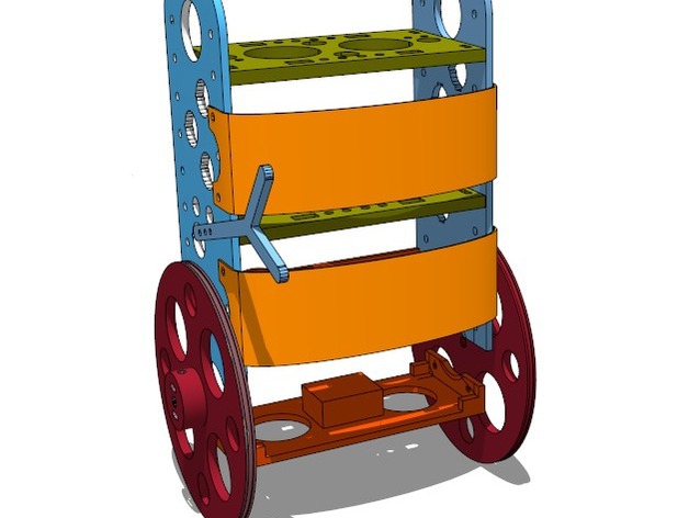
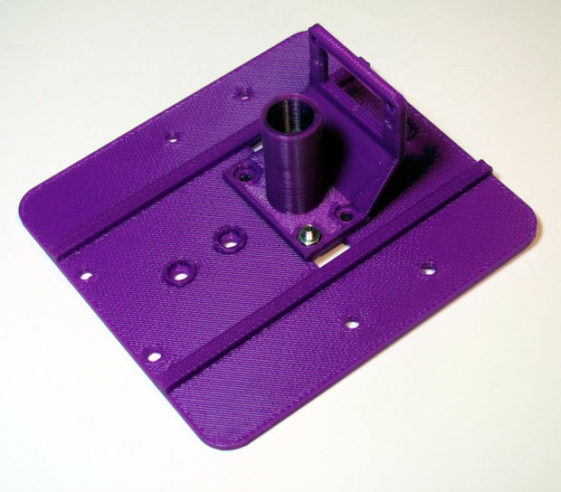
  2. B-Robot 3D printed plastic parts (include bolts+nuts+ON/OFF switch) or print them by yourself (DOWNLOAD B-robot EVO STL 3D parts)
  3. Arduino LEONARDO 
  4. 2x Stepper motor DRIVER (A4988)
  5. IMU (gyro+accelerometer)
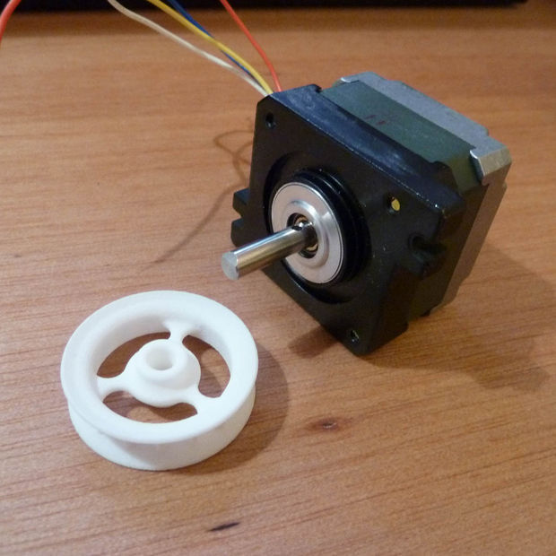
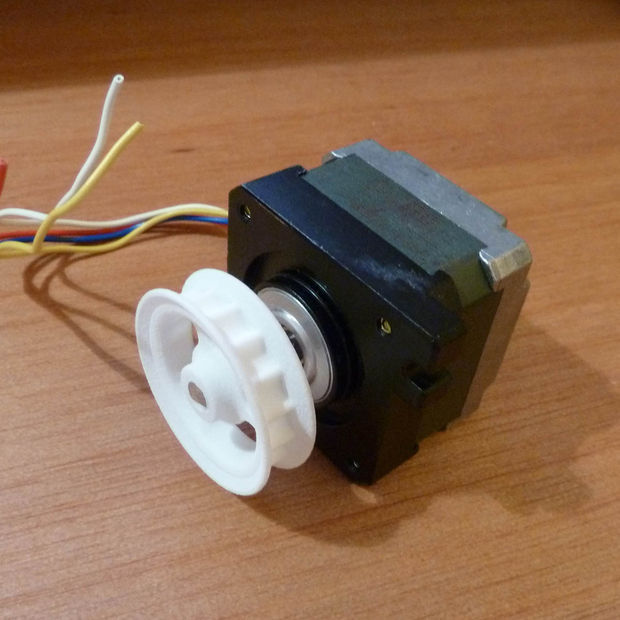
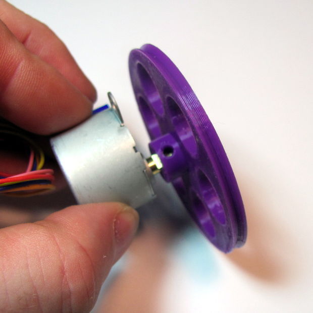
  6. 2x NEMA 17 stepper motors (40mm length, example:42BYGHW609)
  7. 8xAA battery holder (for NiMh or alkaline batteries)
  8. OPTIONAL: Mini servos (21g) to move the arm (arms)
  9. Programming the Leonardo with the latest code (ESP12-E version)
  10. Have a look to the FORUM, there you will find modifications of the robots (sonar sensors, different cases, sizes…)


FAQ: More questions


Why are you using Stepper motors?

There are several options for motors: DC, Brushless, Steppers… We choose stepper motors because they have enough torque, you could connect the wheels directly without gears that generate some backslash (this is a common problem in balancing robots), they have good bearings and you will be able to control the speed of the motors with accuracy. In standard sizes these motors are cheap (we use the same motors used on a regular 3D printers) and the drivers are cheap and easy to interface with Arduino too.

Why you use a Wifi connection?

Using a Wifi connection allow us to work with a lot of devices (Smartphones, Tablets, PCs…) Bluetooth devices are cheaper but their range is usually shorter. Old devices are not supported and you could not connect it to Internet easily. The Wifi module that we recommend, allow us to create an Access Point, so you don’t need to use an existing Wifi infrastructure (cheap Wifi modules don´t let you do this). You can connect your device directly to the Robot anywhere but if you prefer you can hack it and use your own infrastructure therefore controlling your robot (or whatever you have created) over the Internet from any remote place in the world! (Cool, isn´t it?)

Why BROBOT?

Self balancing robots are fun to see and play. A self balancing robot requires sensors and control algorithms. You will find all the HOWTO and technical documents which explains the “behind the scenes” in JJROBOTS. Learn electronics and robotics creating your own BROBOT from scratch!.

There are some commercial solutions to the balancing robot, but here we want to share knowledge and thoughts. You can use the BROBOT parts to create more robots or gadgets, keep in mind all the devices used in a BROBOT are standard devices/electronics with a lot of potential. In the JJROBOTS community we want to show you how! You are now buying a self balancing robot, your are buying your own electronic and ancillary devices!

Thinking about creating a GPS self guidance robot? a modified version of BROBOT is your robot!

How much payload could carry BROBOT?

BROBOT could easily carry your soft-drink cans. We have tested with 500g of payload with success. More weight makes the robot more unstable but this could be fun also, isn’t it?

Why use stepper motors for a balancing robot?

There are several options for motors, DC, Brushless, Steppers… We choose stepper motors because they have enough torque, you could connect the wheels directly without gears that generate some backslash, they have good bearings and you could control the speed of the motors very precisely. Also they are cheap and the drivers too…

Could I use rechargeable batteries of Lipo batteries?

Yes, you could use standard AA batteries (alkaline recommended), AA rechargeable batteries (e.g. NiMh) or you could optionally use a 3S Lipo battery. Run Lipo batteries at your own responsibility.

What is the runtime of BROBOT?

With rechargeable AA batteries (e.g. Ni-Mh 2100mAh) you could expect around half to an hour of runtime

Could BROBOT work without the wifi module?

Yes, BROBOT could work and keep its stability. But, of course you could not control it without the module.

Could I change the name of the Wifi network that BROBOT generate?

Yes, on the configuration sketch you could change the name and also some other internet configurations. You could also connect BROBOT with your existing Wifi network

Is this a project for an Arduino beginner?

Well, BROBOT is not an easy “beginner project”, but it has a lot of documentation so you have a platform to grow your skills. You could first mount your BROBOT following the instructions and it should work OK, then you could start understanding some parts of the code and finally writing your own pieces of code…

For example it could be easily (there are tutorials for this) to write your code so the robot automatically move the arm and spin itself if you don’t send a command in 10 seconds…

More advanced hacks: Convert to a totally autonomous robot with obstacle avoiding adding a SONAR, convert to a follow line robot, and so on…

Why BROBOT electronics are not so cheap?

We are a really small startup (2 persons in our free time) and now we could only run small batch of electronics. As yo know the price of electronics drops quickly in high volume productions but we are starting… If we sell many boards and we could run more volume productions we will drop the prices!!. JJROBOTS didn´t born to get money, our spirit is to sell “good products” to found our next projects and spread the robotics knowledge

If you want to know more, we recommend you have a look at the B-ROBOT´s code (or to the jjrobots forum).


jjrobotsJJROBOTS Science&fun 2015

MobBob V2 Remix Upgrade – Smart Phone Controlled Robot

[Update 20160212]
Add MobBob2_Remix_PowerBank_Hook.stl
Add MobBob2_Remix_Jacket.stl
Add MobBob2_Remix_Nano_Shield_Mount.stl

[Update 20160120]
Add Test #3 Video

[Update 20160119]
Add Test #1, #2 Video
Add MobBob2_Remix_Hand_Back_L.stl, MobBob2_Remix_Hand_Front_L.stl
Add MobBob2_Remix_Arm_Back_L.stl, MobBob2_Remix_Arm_Front_L.stl
Add MobBob2_Remix_Shoulder_L.stl
Add MobBob2_Remix_Hand_Back_R.stl, MobBob2_Remix_Hand_Front_R.stl
Add MobBob2_Remix_Arm_Back_R.stl, MobBob2_Remix_Arm_Front_R.stl
Add MobBob2_Remix_Shoulder_R.stl

[Update 20160105]
Printing errors corrected
MobBob2_Remix_Foot_L_Top.stl, MobBob2_Remix_Foot_R_Top.stl

[Upgrade 20160104]
Redesign Foot
MobBob2_Remix_Foot_L_Top.stl, MobBob2_Remix_Foot_L_Floor.stl
MobBob2_Remix_Foot_R_Top.stl, MobBob2_Remix_Foot_R_Floor.stl
Base Design: http://www.thingiverse.com/thing:1232619


Smart Phone Controlled Robot – MobBob V2 Remix Upgrade


3D Design Tool: SketchUp Pro
Design concept: RAPIRO – The Humanoid Robot and Gundam

This is an upgrade version of my MobBob V2 Remix robot.

MobBob is a smart phone controlled robot. By harnessing the power of your smart phone, MobBob is a walking, talking robot with voice recognition and computer vision that you can build for around $35. I will be continuing to extend his features over time. I want MobBob to be a companion robot that everyone can afford and have fun with.

You can see videos of MobBob V2 Remix upgrade in action here:
https://youtu.be/8nO0kziJvsk – 3D Design
https://youtu.be/ehrsIDJcVZY – Test #1
https://youtu.be/j0oz8OPYhNs – Test #2
https://youtu.be/5z4Ps11t-vE – Test #3
…..
Coming soon!!

The main aims of the V2 remix were to:

Support standard 9g servos [previously I was using Tower Pro SG90 servos]
Make everything easier to assemble [no more need for glue]
Make it easier to adapt/modify for other phones. The new bracket system made it easier to exchange a new phone / the battery holder.

Also, in my V2 Remix Upgrade build, I’m also using the Arduino Nano instead of the DIY Nano shield, so the entire build is smaller and tidier. 🙂

MobBob V2 Remix Upgrade uses the same software as the original RAPIRO.

You can find the latest Arduino code here: https://github.com/Ishiwatari/RAPIRO
The modified code is included: http://www.thingiverse.com/thing:1235865

You can download the latest version of the Android from Google Play – it is free, ad-free, and without IAP:
https://play.google.com/store/apps/details?id=com.github.luzhuomi.rapicommand

You can find more detailed build and wiring instructions here:
…coming soon…

The parts that you need to print:

1 x Leg Left
1 x Leg Right
1 x Foot Left Floor
1 x Foot Right Floor
1 x Foot Left Top
1 x Foot Right Top
1 x Waist
1 x Arduino Nano Holder
1 x Phone Mount Base
2 x Phone Mount Side
1 x Phone Mount Gear
1 x Phone Mount Back Plate
1 x Phone Mount Conn
2 x Phone Mount Bolt
2 x Phone Mount Nut
1 x Battery Bank Rack [18650 x 2] or Power Bank
1 x Battery Mount Cover or PowerBank Hook
1 x Jacket
1 x Cap
1 x Hand Back Left
1 x Hand Front Left
1 x Arm Back Left
1 x Arm Front Left
1 x Shoulder Left
1 x Hand Back Right
1 x Hand Front Right
1 x Arm Back Right
1 x Arm Front Right
1 x Shoulder Right

The non-3D printed parts you need are:

6 x Tower Pro SG90 servos [for Shoulders, Arms and Hands]
4 x EMAX ES08MA II Mini Metal Gear Analog Servo [Strengthening the power of the Legs and Foots]
1 x Arduino Nano ATmega328 [see note below]
1 x HM-10 BLE Bluetooth 4.0 CC2540 CC2541 Serial Wireless Module [or HC-05]
1 x 5V Micro USB 1A Lithium Battery Charging Board [see note below]
1 x DC-DC Converter Step Up Boost Module 2-5V to 5V 1.2A
1 x Rectangle On/Off Long Rocker Switch SPST
2 x Snap-In Single ‘A’-‘AA’ Battery Contacts 209 [KEYSTONE ELECTRONICS CORP.]
2 x Snap-In Single ‘A’-‘AA’ Battery Contacts 228 [KEYSTONE ELECTRONICS CORP.]
2 x 18650 Lithium ion Batteries
1 x 300mm USB 2.0 A Male to Micro USB B 5pin + Mini B Male Y Splitter Cable
1 x Smart Phone [see note below]
4 x M3 5mm [for Foot Cover]
2 x M2 10mm [for Phone Connect]
4 x M2 5mm [for Phone Mount Back Plate]
2 x 2mm 5mm Tapping screw [for Foot servos]
2 x 2mm 8mm Tapping screw [for Hip servos]
2 x 1mm 5mm Tapping screw [for Foot servos hone]
2 x 1mm 8mm Tapping screw [for Hip servos hone and Shoulder]
2 x M3 15mm [for Jacket]
2 x M3 Nut [for Jacket]
4 x 2mm 15mm Tapping screw [for Jacket]
12 x M2 15mm [for Arm and Hand]
[Note: I got the servos, Arduino Nano, Bluetooth Module and Battery for under $30.]

Arduino Nano:

This is a small, Arduino compatible ATmega328 board with DIY extension board. MobBob V2 app connects to the Bluetooth module using its Bluetooth LE service. The app to support other Bluetooth cards.

Battery Extender:

You can use other batteries that provide 5V with a steady current. If you use other batteries, you may need to adapt the battery rack for your battery’s size.
Use 18650 Lithium Battery Charging Board With Protection Charger Module and Step Up Boost Module 3.7V to 5V for Smart Phone
http://www.thingiverse.com/thing:1235749

Smart Phone:

You can use other Android Smart Phones with This app.
You do not need to adapt the size of the phone holder for your phone. The app has been successfully tested with Nexus and Samsung, LG phones, but should work on other Android phones.

Instructions:

Print all the required parts
Get all the non-3D printed parts
Assemble as per the photos – I’ll be writing some more detailed instructions on my website soon!
Install the Arduino code from the GitHub link in the description – You will need to update the Arduino pins in the code to match yours, and probably update the centering values for the servos.
Install the Android app from the link in the description.

Have fun!

If you hit any problems, please post a question on this website: [http://www.rapiro.com], here, or on YouTube channel. A few people have built RAPIRO now, so there are people around who can help.

Coming soon update!!

The open source Mobbob V2 software and hardware is free and made with love. Please show your level of support with a voluntary donation.

Donate:
https://www.paypal.com/cgi-bin/webscr?cmd=_s-xclick&hosted_button_id=RDN7ZGAVFS5UE

Post-Printing

How I Designed This

Design Tool

Google SketchUp Pro 8

Print Settints

Printer Model: PANDORA DXs – DIY 3D Pronter
Slicer: Cura 15.04.2


Layer height (mm): 0.1
Shell thickness (mm): 0.8

Bottom/Top thickness (mm): 1.2
Fill Density (%): 00

Print speed (mm/s): 50
Print temperature: 200
Bed temperature: 70

Support type:

  • Touching buildplate:
    MobBob2_Remix_Phone_Mount_Side.stl,
    MobBob2_Remix_Phone_Mount_Nut_L.stl, MobBob2_Remix_Phone_Mount_Nut_R.stl,
    MobBob2_Remix_Phone_Mount_Conn.stl,
    18650_Battery_Bank_2x_Cover_swC_r01.stl
  • Everywhere:
    MobBob2_Remix_Nano_Shield_Holder.stl,
    MobBob2_Remix_Battery_Mount_Cover.stl,
    MobBob2_Remix_Jacket.stl,
    MobBob2_Remix_Hand_Back_L.stl, MobBob2_Remix_Hand_Front_L.stl,
    MobBob2_Remix_Arm_Back_L.stl, MobBob2_Remix_Arm_Front_L.stl,
    MobBob2_Remix_Shoulder_L.stl,
    MobBob2_Remix_Hand_Back_R.stl, MobBob2_Remix_Hand_Front_R.stl,
    MobBob2_Remix_Arm_Back_R.stl, MobBob2_Remix_Arm_Front_R.stl,
    MobBob2_Remix_Shoulder_R.stl

Platform adhesion type: Brim

Filament: PLA
Filament Diameter (mm): 1.75


3D Files:

https://www.thingiverse.com/thing:1235865

Custom Section

Source code

by ShotaIshiwatari is licensed under the Creative Commons – Public Domain Dedication license.
modified by Zalophus

on the command line, enter:
// #M1 – robot will move forward
// #M2 – robot will move backward
// #M3 – robot will turn right
// #M4 – robot will turn left
// #M5 – robot will raise his hand and wave the left hand. LED will become green and flashing
// #M6 – robot will lower his left hand. LED will become Yellow
// #M7 – robot will move both arm and contract his hands. LED will become Blue
// #M8 – robot will wave goodbye with his left arm. LED will become RED.
// #M9 – robot will raise its right arm and move its waist. LED will become BLUE
// #M0 – robot will go to initial position

CAPS LOCK is important when you input a command via the serial monitor..
Reading through the source code.
Each movement of the preset (# M1 ~ # M9), consists of pattern of 8 frames.
Each frame is defined values ​​uint8_t type sixteen (motion).
This can be changed modifying the number of frame per pattern.MAXFN
Lets take #M0 for example:

uint8_t motion[MAXMN][MAXFN][16]={
{ // 0 Stop
{ 90, 90, 0,130, 90,180, 50, 90, 90, 90, 90, 90, 0, 0,255, 10},
{ 90, 90, 0,130, 90,180, 50, 90, 90, 90, 90, 90, 0, 0, 0, 0},
{ 90, 90, 0,130, 90,180, 50, 90, 90, 90, 90, 90, 0, 0, 0, 0},
{ 90, 90, 0,130, 90,180, 50, 90, 90, 90, 90, 90, 0, 0, 0, 0},
{ 90, 90, 0,130, 90,180, 50, 90, 90, 90, 90, 90, 0, 0, 0, 0},
{ 90, 90, 0,130, 90,180, 50, 90, 90, 90, 90, 90, 0, 0, 0, 0},
{ 90, 90, 0,130, 90,180, 50, 90, 90, 90, 90, 90, 0, 0, 0, 0},
{ 90, 90, 0,130, 90,180, 50, 90, 90, 90, 90, 90, 0, 0, 0, 0}
},

I put numbers so you can visualy make sense of what a pattern is, and what a frame contain.
Movements consist of pattern. Pattern are made of frames. Each frame contrain the rotation angle of every servo, the values of the RGB LED and a Time to perform the action.

Head horizontal rotation angle (Head yaw) (left) 180 <—> 0 (right)
Hip horizontal rotation angle (Waist yaw) (left) 180 <—> 0 (right)
Right shoulder up and down angle (R Shoulder yaw) (bottom) 0 <—> 180 (above)
Open right shoulder angle (R Shoulder pitch) (closed) 90 <—> 180 (open)
Right hand opening and closing angle (R Hand grip) (closed) 50 <—> 110 (open)
Left shoulder up and down angle (L Shoulder yaw) (bottom) 180 <—> 0 (top)
Open left shoulder angle (L Shoulder pitch) (closed) 90 <-> 0 (open)
Left hand opening and closing angle (L Hand grip) (closed) 130 <—> 70 (open)
Right foot horizontal rotation angle (R Foot yaw) (left) 0 <—> 180 (right)
Twist angle of the right foot ankle (R Foot pitch) () 0 <—> 180 (outside)
Left foot horizontal rotation angle (L Foot yaw) (left) 0 <—> 180 (right)
Twist angle of the left foot ankle (R Foot pitch) (within) 180 <—> 0 (outside)
Red component of the eye (R) 0 <—> 255
Green component of the eye (G) 0 <—> 255
Blue component of the eye (B) 0 <—> 255

Here are some other helpful commands that can be used to control the LED and each servos individually.

LED CODE sample

// #PR000G255B000T010 – MAX GREEN COLOR
R,G,B values between 0 and 255
T is the time component to get to desired color

LIMBS MOVEMENT
Sxx refers to one of the 12 motors (from S00 to S11),
A000 up to A180 is the angle where to servo incline,
Txxx is the time to perform the movement.
you can combine two commands, i tried more but it didn’t work..

// #PS00A000T010#PS00A180T010 – full head movement from side to side
// #PS01A000T010#PS01A180T010 – Waist
// #PS02A000T010#PS02A180T010 – r Shoulder
// #PS03A050T010#PS03A180T010 – r Arm
// #PS04A030T010#PS04A140T010 – r HAND
// #PS05A000T010#PS05A180T010 – l Shoulder
// #PS06A130T010#PS06A010T010 – l Arm
// #PS07A030T010#PS07A180T010 – l hand
// #PS08A000T010#PS08A180T010 – r Foot yaw
// #PS09A000T010#PS09A180T010 – r Foot pitch
// #PS10A000T010#PS10A180T010 – l Foot yaw
// #PS11A000T010#PS11A180T010 – l Foot pitch

// #PS00A090S01A090S02A000S03A090S04A090S05A180S06A090S07A090S08A090S09A090S10A090S11A090R000G000B000T005

MobBob V2 Remix – Smart Phone Controlled Robot

[Update 20160111]
Add test video and photos

[Update 20160109]
Modify MobBob2_Remix_Jacket_L.stl
Modify MobBob2_Remix_Jacket_R.stl
Modify MobBob2_Remix_Battery_Mount_Cover.stl

[Update 20160105]
Add Shield board file Arduino_Nano_Shield_REV3.brd [Eagle CAD file]
Add modified source code MobBob2_Remix_Contol_Bluetooth.ino to .zip

[Upgrade 20160104]
Redesign Foot
MobBob2_Remix_Foot_L_Top.stl
MobBob2_Remix_Foot_L_Floor.stl
MobBob2_Remix_Foot_R_Top.stl
MobBob2_Remix_Foot_R_Floor.stl

[Update 20160102]
Add MobBob2_Remix_Cap.stl
Add MobBob2_Remix_Battery_Mount_Cover.stl
Add MobBob2_Remix_Jacket_L.stl
Add MobBob2_Remix_Jacket_R.stl

[Update 20151231]
Add Photos
Add 18650_Battery_Bank_2x_r01.stl
Add 18650_Battery_Bank_2x_Cover_swC_r01.stl


Smart Phone Controlled Robot – MobBob V2 Remix


3D Design Tool: SketchUp Pro
Design concept: RAPIRO – The Humanoid Robot and Gundam

This is an remix version of my MobBob robot.

MobBob is a smart phone controlled robot. By harnessing the power of your smart phone, MobBob is a walking, talking robot with voice recognition and computer vision that you can build for around $20. I will be continuing to extend his features over time. I want MobBob to be a companion robot that everyone can afford and have fun with.

You can see videos of MobBob V2 Remix in action here:
https://youtu.be/fE7024whSF8
https://youtu.be/aZaUMOi9q0k
https://youtu.be/LGFUjzvBPuI
…..
Coming soon!!

The main aims of the V2 remix were to:

Support standard 9g servos [previously I was using Tower Pro SG90 servos]
Make everything easier to assemble [no more need for glue]
Make it easier to adapt/modify for other phones. The new bracket system made it easier to exchange a new phone / the battery holder.

Also, in my V2 Remix build, I’m also using the Arduino Nano instead of the DIY Nano shield, so the entire build is smaller and tidier. 🙂

MobBob V2 Remix uses the same software as the original MobBob V2.

You can find the latest Arduino code here: https://github.com/cevinius/MobBob
The modified code is included: MobBob2_Remix_Control_Bluetooth.ino

You can download the latest version of the Android app from Google Play – it is free, ad-free, and without IAP:
https://play.google.com/store/apps/details?id=com.cevinius.MobBob

You can find more detailed build and wiring instructions here:
…coming soon…

The parts that you need to print:

1 x Leg Left
1 x Leg Right
1 x Foot Left………………………………Delete
1 x Foot Right…………………………….Delete
1 x Foot Cover Left……………………..Delete
1 x Foot Cover Right……………………Delete
1 x Foot Left Top
1 x Foot Right Top
1 x Foot Left Floor
1 x Foot Right Floor
1 x Waist
1 x Arduino Nano Holder
1 x Phone Mount Base
2 x Phone Mount Side
1 x Phone Mount Gear
1 x Phone Mount Back Plate
1 x Phone Mount Conn
2 x Phone Mount Bolt
2 x Phone Mount Nut
1 x Battery Bank Rack [18650 x 2]
1 x Battery Mount Cover
1 x Jacket Left
1 x Jacket Right
1 x Cap

The non-3D printed parts you need are:

4 x Tower Pro SG90 servos
1 x Arduino Nano ATmega328 [see note below]
1 x HM-10 BLE Bluetooth 4.0 CC2540 CC2541 Serial Wireless Module
1 x 5V Micro USB 1A Lithium Battery Charging Board [see note below]
1 x DC-DC Converter Step Up Boost Module 2-5V to 5V 1.2A
1 x Rectangle On/Off Long Rocker Switch SPST
2 x Snap-In Single ‘A’-‘AA’ Battery Contacts 209 [KEYSTONE ELECTRONICS CORP.]
2 x Snap-In Single ‘A’-‘AA’ Battery Contacts 228 [KEYSTONE ELECTRONICS CORP.]
2 x 18650 Lithium ion Batteries
1 x 300mm USB 2.0 A Male to Micro USB B 5pin + Mini B Male Y Splitter Cable
1 x Smart Phone [see note below]
4 x M3 5mm [for Foot Cover]
2 x M2 10mm [for Phone Connect]
4 x M2 5mm [for Phone Mount Back Plate]
2 x 2mm 5mm Tapping screw [for Foot servos]
2 x 2mm 8mm Tapping screw [for Hip servos]
2 x 1mm 5mm Tapping screw [for Foot servos hone]
2 x 1mm 8mm Tapping screw [for Hip servos hone]
2 x M3 15mm [for Jacket]
2 x M3 Nut [for Jacket]
4 x 2mm 15mm Tapping screw [for Jacket]
[Note: I got the servos, Arduino Nano, Bluetooth Module and Battery for under $30.]

Arduino Nano:

This is a small, Arduino compatible ATmega328 board with DIY extension board. MobBob V2 app connects to the Bluetooth module using its Bluetooth LE service. The app to support other Bluetooth cards.

Battery Extender:

You can use other batteries that provide 5V with a steady current. If you use other batteries, you may need to adapt the battery rack for your battery’s size.
Use 18650 Lithium Battery Charging Board With Protection Charger Module and Step Up Boost Module 3.7V to 5V for Smart Phone
http://www.thingiverse.com/thing:1235749

Smart Phone:

You can use other Android Smart Phones with This app.
You do not need to adapt the size of the phone holder for your phone. The app has been successfully tested with Nexus and Samsung, LG phones, but should work on other Android phones.

Instructions:

Print all the required parts
Get all the non-3D printed parts
Assemble as per the photos – I’ll be writing some more detailed instructions on my website soon!
Install the Arduino code from the GitHub link in the description – You will need to update the Arduino pins in the code to match yours, and probably update the centering values for the servos.
Install the Android app from the link in the description.

Have fun!

If you hit any problems, please post a question on this website: [http://www.cevinius.com], here, or on YouTube channel. A few people have built MobBobs now, so there are people around who can help.

Coming soon update!!


Print Settings


Printer: PANDORA DXs – DIY 3D Printer
Slicer: Cura 15.04.2

Layer height (mm): 0.1
Shell thickness (mm): 0.8

Bottom/Top thickness (mm): 1.2
Fill Density (%): 00

Print speed (mm/s): 50
Print temperature: 200
Bed temperature: 70

Support type:

  • Touching buildplate:
    MobBob2_Remix_Phone_Mount_Side.stl,
    MobBob2_Remix_Phone_Mount_Nut_L.stl,
    MobBob2_Remix_Phone_Mount_Nut_R.stl,
    MobBob2_Remix_Phone_Mount_Conn.stl,
    18650_Battery_Bank_2x_Cover_swC_r01.stl
  • Everywhere:
    MobBob2_Remix_Nano_Shield_Holder.stl
    MobBob2_Remix_Battery_Mount_Cover.stl
    MobBob2_Remix_Jacket_L.stl
    MobBob2_Remix_Jacket_R.stl

Platform adhesion type: Brim

Filament: PLA
Filament Diameter (mm): 1.75


3D Files:

https://www.thingiverse.com/thing:1232619

ESPway | 로봇 제어 세그웨이 스타일 와이파이 ESP8266 구축

내가 아두 이노와 임베디드 시스템 땜질 시작 이후로, 나는 자기 밸런싱, 세그웨이 같은 로봇을 구축하는 방법에 대해 매우 흥분했습니다. 인터넷의 주위에 유사한 프로젝트 및 리소스는 매우 풍부하다.

첫 번째 프로토 타입은 플라스틱 도시락 상자 안에 지어졌습니다. 그것은 아두 이노 나노 사용 원격 제어를 적외선. 그것은 사용 MPU6050 로봇의 방향을 검출하기위한 관성 측정 유닛. 균형은 매우 잘 작동하지만, 적외선 원격 제어는 매우 비실용적이고 신뢰할 수 있었다.

내가 대해 알게되었을 때이 프로젝트는 부활 ESP8266 , 매우 강력한 코어의 저렴한, 와이파이 활성화 마이크로 컨트롤러. 웹 개발에 대한 배경을 갖는, 와이파이 연결이 나에게 가능성의 세계처럼 보였다.

전통적 아두 이노 커뮤니티 원격 제어 로봇은 블루투스 통신을 이용하여 구현되어왔다. 그러나, 이것은 실질적으로 컨트롤러 소프트웨어를 각 플랫폼에 개별적으로 구현되어야한다는 것을 의미한다 (안드로이드, 아이폰 OS, PC 등)

HTML과 자바 스크립트로 구현 웹 애플리케이션은 점점 더 인기를 끌고있다. 이유 중 하나는 휴대 성이다. 웹 응용 프로그램을 한 번 작성되면, 그것은 충분히 좋은 웹 브라우저가있는 모든 플랫폼에서 실행할 수 있습니다.

ESP8266은 WiFi 액세스 포인트로 구성 될 수있다. 하나는 웹 응용 프로그램 서비스를 제공하기 ESP8266이 가능하고, 정적 페이지를 제공하는 HTTP 서버를 설정할 수 있습니다. 로봇 제어 소프트웨어는 웹 응용 프로그램으로 구현 된 경우 이제 상상! 그건 내 프로젝트 ESPway 뒤에 키 생각이다.

이 작은 로봇에 대한 코드와 회로도를 찾을 수 있습니다 GitHub의에 . 구축 개발 및 소프트웨어 사용에 대한 사전 설명이 있습니다. 또한이 사용자 설명서의 어떤 종류를 짓고 있어요. 이 프로젝트는 또한 한 레딧에 논의 나는 비디오를 게시 할 때 얼마 전에.

안전 제일

깊은 기술적 인 세부 사항에 다이빙하기 전에, 그래도 난 당신이 스스로를 구축하려고하는 경우 안전에 대해 경고한다.

전자 및 소프트웨어는이 글을 쓰는 현재의 (저전압 차단 제외) 안전 기능이 포함되어 있지 않습니다. ESP8266의 펌웨어 (이것은 아마도 수 / 노점을 충돌하는 경우  일), 회전에서 모터를 중지 아무것도 없다. 이 로봇은 작은 및 그 주변을 손상하지 충분히 빛이 내 경우에는 특별한 문제가되지 않습니다. 그러나,이 로봇의 크고 무거운 버전을 제작하기 전에 안전을 고려하시기 바랍니다. 하나는 아마도 소프트웨어 오류의 경우에 모터를 차단 할 몇 가지 안전 장치 시스템을 구현할 수 있습니다.

전자 및 기계

이 로봇 부품의 대부분은 이베이 나 AliExpress에서 공급된다. 전체 회로도는 GitHub의에서 찾을 수 있습니다. 이 프로젝트의 목표 중 하나는 가능한 한 간단하고 저렴한 전자를 유지했다.

로봇의 핵심은 ESP8266 마이크로 컨트롤러가있다. 그것은 독립 구성 요소로 사용되지하지만 거기 WEMOS D1 미니보드. 그것은 USB 커넥터와 펌웨어를 업로드하기위한 USB-에-UART 컨버터를 가지고있다.

MPU6050는 방위 센서로서 사용된다. 그것은 I2C를 통해 통신, 사용 가능한 저렴한 브레이크 아웃 보드의 많음이있다. 나는 GY-521라는 하나를 데 사용합니다.

모터는 통합 금속 기어 박스와 평범한 오래된 DC 모터입니다. 공칭 회전 속도는 300 rpm으로, 그리고 그들은 6V에 대한 평가된다. 하나는 “N20의 300RPM”또는 “12ga의 300RPM”를 검색하여 이러한 모터를 찾을 수 있습니다.

모터가 구동되어 L293D 듀얼 H 브리지 모터 드라이버 IC. 그 로봇을 구축 할 때 내가 손에 가지고 무엇 때문에이 IC는 주로 선택되었다. 바이폴라 트랜지스터의 출력은 다리를 건너 큰 전압 강하를 생산 이제 나는 배웠다. 결국 내가 가진 드라이버 교체 할 수 있습니다 DRV8833 MOSFET 출력을 가지고있다.

나는 로봇에 전력을 공급하기 위해 2 셀 리튬 폴리머 배터리를 사용하고 있습니다. 완전히 충전 된 때 ~ 8.4 볼트를 제공합니다. 전지 전압은 ESP8266의 아날로그 입력을 통해 모니터되고, 배터리 전압이 소정의 임계 값 아래로 떨어질 때, 모터를 차단하는 선택적인 특징이있다. 즉 리튬 폴리머 배터리를 사용하는 것이 일반적이다. 아날로그 입력 범위는 0-1 볼트이다. 3.3 다음 D1 미니 보드, 이미 1의 비율로 분압기있다. 따라서 I은 아날로그 입력 범위에 적합하도록 배터리 전압 스케일링 1:10 비율로 수정 한 저항을 추가했다.

마지막으로,이 WS2812B의 NeoPixels은 로봇의 “눈”으로 추가됩니다. 그들은 (OTA 업데이트 등을 진행있을 경우이 떨어진 경우) 로봇의 현재 상태를보고 매우 유용 증명

크기와 무게의 최적화를 설계 목표로 설정 한 것을 다른 역학에 대해 말을 많이가 아니다. 프로토 타입 몸은 4mm 합판의 일부 조각의 내장 및 에폭시와 함께 붙어있다.

로봇의 일반보기

소프트웨어 플랫폼

현재 자원과 ESP8266에 소프트웨어를 개발하기위한 지원의 재산이있다. 제조업체 Espressif하는 RTOS없이 운영 체제와 다른 하나 하나가 제공하는 두 개의 SDK가 있습니다. 도있다 아두 이노 코어 의 심바 크로스 플랫폼 RTOS 프레임 워크와 MicroPython은 . 새로운 언어와 프레임 워크가 큰 인 지금 가끔씩 튀어 나올 것 같다!

이 로봇에 대한 몇 가지 프로토 타입을 사용하여 아두 이노 코어에서 수행 된 PlatformIO를 빌드 시스템으로. 프로토 타입 작업은에서 찾을 수 있습니다 해당 지점 GitHub의의 REPO의.

그러나 최대의 유연성과 제어를 위해, 나는 제조업체의 “비 OS”SDK로 전환. 하나는이 마이크로 컨트롤러와 함께 얻을 수있는 즉 약으로 기본입니다. 나는 특히,이 SDK에 사용할 멋진 도서관이 있었다 찾을 수 기쁘게 생각 libesphttpd 간단한 HTTP 서버와 파일 시스템을 구현한다. 그것은 또한 웹 소켓 통신 시설을 갖추고으로이 프로젝트를위한 안성맞춤이었다.

모바일 웹 UI

로봇에 전원을 공급하고, WiFi 액세스 포인트에 클라이언트 장치를 연결 한 후, 하나는 기본 IP 주소에서 웹 브라우저 사용자 인터페이스를 열 수 있습니다 192.168.4.1.

나는 가능한 한 간단하게 UI를 유지하기 위해 노력했다. 그것은 본질적으로 HTML5 캔버스에 그려진 가상 “조이스틱”로 구성되어 있습니다. 터치 디바이스에서 휴대 전화 등, 꽤 직관적 인 느낌.

조정에 사용되는 사용자 인터페이스.

의 URL에서 로봇의 PID 매개 변수의 온라인 튜닝을위한 UI도 있습니다 /pid. 그것은 진행중인 작품이지만, 반 사용 가능한 상태에서 이미. 그것은 본질적으로 펌웨어를 매개 변수가 변경 될 때마다 다시 깜박하지 않고 한 번에 로봇을 조정 할 수 있습니다. 하나는 UI를 통해 플래시 메모리에 조정 매개 변수를 저장할 수 있습니다.

초기 PID 튜닝 사용자 인터페이스를 제공합니다.

웹 소켓을 통해 대기 시간이 짧은 통신

아마이 프로젝트의 가장 흥미로운 부분은 낮은 지연 시간 원격 제어를 달성하는 방법이다.

전통적으로 사람들은 ESP8266에 HTTP API가 어떤 종류의를 구현하고있다. 그것은 각 명령에 대해 별도의 URL가 있다는 것을 의미한다. 예는 로봇 차, 같은 URL이있을 것 /forward/backward/stop/turn-left/turn-right등 다음 만들 것 클라이언트 응용 프로그램 AJAX의 로봇을 제어하는 요청을. 그러나, TCP 연결을 열고 모든 명령에 구문 분석 HTTP 헤더가있을 것입니다 의미합니다. 즉, 불필요한 오버 헤드 및 지연을 도입한다. 이 컨트롤은 그런 식으로 매우 부드러운 없을 것이다.

더 나은 대안은 열려있는 TCP 소켓을 유지하고 두 방향으로 그것을 통해 정보를 전송하는 것입니다. ESP8266 원시 TCP 통신을위한 일류 지원을하고 있지만, 자바 스크립트 하나는 원시 TCP 소켓을 열 수 없습니다. 대신있다 WebSockets를 정의 된 핸드 쉐이킹 프로토콜 및 데이터 프레임 포맷 첨가 TCP 소켓이다. 때문에 libesphttpd웹 소켓 구현을 가지고, 나는이 세부 사항에 대해 걱정하지 않았지만, 단지 데이터 패킷을 교환한다.

데이터 패킷의 첫 번째 바이트에 해당되는 명령을 표시하고, 이후의 추가 바이트 데이터이다 : 거기 로봇와 UI 사이에 통신하는 매우 단순한 프로토콜이다. 부가 데이터의 길이는 각각의 명령에 대한 알려진 고정된다. 예를 들어, 클라이언트에 의해 전송 된 “스티어링”데이터 패킷은 3 바이트로 구성 첫 번째 바이트 (즉, 같은 코드로 정의되어 제로 STEERING). 두번째 바이트는 원하는 속도를 나타내고, 세 번째는 회전 속도를 나타내는 (네거티브 = 좌, 포지티브 = 우측). 이 경우, 두 번째 및 세 번째 바이트는 8 비트 부호있는 정수로 해석된다. 데이터 바이트의 해석은 문제의 명령에 따라 달라집니다.

부드러운 양방향 통신을 감안할 때, 하나는 멋진 모든 종류의 것들을 구현할 수 있습니다. 예를 들어, 로봇은 클라이언트 웹 응용 프로그램에서 배터리 모니터링을 허용, 연결된 모든 클라이언트에 현재 배터리 독서를 보낼 수 있습니다. 또한, 가장 실용적인 것들 중 하나는 PID 컨트롤러 매개 변수의 온라인 튜닝이다.

데이터 바이트의 C 코드, 조작 및 천연 재 해석된다. 자바 스크립트에서는, 이진 데이터는로 표현되는 ArrayBuffer원시 이진 데이터의 블록의 표현은 본질적이다. 액세스 및 수정하려면, 하나는 사용할 수 있습니다 DataView기본 바이너리 버퍼에 바이트 수준의 액세스를 제공한다. 하나는 예를 들어 “바이트의 16 비트 부호없는 정수 (리틀 엔디안)로 13 쓰기 버퍼의 처음부터 오프셋 2″라고 할 수있다. 나는 자바 스크립트 API를 제공 낮은 수준의 제어가 찾을 수 놀랐다.

고정 소수점 센서 퓨전

I2C를 통해 MPU6050와 통신하는 것은 쉽다. 하나는 1 kHz에서 업데이트되는 세 축의 가속도와 자이로 측정치를 포함하는 하드웨어 레지스터를 판독 할 수있다. 배향으로이 값을 변환하는 과정은 “센서 퓨전”라고한다. 거기를 수행하는데 사용될 수 센서 자체로 신호 처리 코어이고,이 우수한 I2Cdevlib것을 구현한다. 그러나, 내가하고 싶지 않은 무언가 센서에 바이너리 펌웨어 덩어리를 업로드해야합니다. 또한, 그 알고리즘은 미가공 데이터는 1 kHz에서 사용할 경우에도 200 Hz의 샘플링 레이트만을 할 수있다.

주어진 ESP8266가 가진 32 비트 코어를 가지고 16 * 16 -> 32 비트 곱셈 확대, I 센서 융합하는 대신에 구현 될 수 있다고 생각. 가장 특히, 선택할 수있는 많은 알고리즘이 있습니다 보완 필터 , 칼만 필터 와 Madgwick 필터 . 후자는 독창적으로 작동 최첨단 신규 알고리즘 쿼터니온 방향의 표현. 또한이 시작하는 데 사용할 수 몇 가지 예제 코드이었다, 그래서 Madgwick 알고리즘이 선택되었다.

ESP8266는 부동 소수점 유닛이 골대를 벗어났습니다하고, 부동 소수점 연산은 소프트웨어로 구현해야합니다. 즉, 복잡한 비즈니스 컴파일러 지원 라이브러리에서 수행되었지만, 그것은 아주 느리다. 따라서, 나는 완전히 알고리즘의 부동 소수점 숫자의 사용을 방지하기 위해 원했다. 따라서 나는 Q16.16에 샘플 코드를 번역하기로 결정했습니다 고정 소수점 숫자 표현을 . 고정 점은 우리가 기본적으로 정수를 위해 노력하고 있지만, 16 최하위 바이트가 소수 부분으로 촬영 한 것을 의미한다.

구현에 대한 하나 개의 좋은 실용적인 세부 다음 Madgwick 알고리즘에, 하나는 어떤 경우에 벡터와 사원 수를 정상화해야한다. 이 경우 정규화는 제곱근으로 나눈 것을 의미한다. ESP8266의 핵심은 하드웨어 부문을 가지고 있지 않기 때문에이 소프트웨어에서 구현 될 필요가 있습니다. 동일은 제곱근에 적용됩니다. 우리는 어떻게 든 그것을 피할 수있는 경우에 따라서는 개별적으로 두 작업을 수행하는 것이 훨씬 이해가되지 않습니다. 반면에, 곱셈 연산의 측면에서 상대적으로 저렴합니다. 제곱근 나누면 제곱근의 역수를 곱한 것과 같다. 즉 여기에서 이루어졌다 무슨 – 상호 제곱근 함수의 라인을 따라 구현 이 StackOverflow의 대답 .

캐스케이드 PID 제어

어떻게 로봇이 실제로 균형을 유지합니까? 지금까지 우리는 로봇의 방향의 좋은 평가가 있습니다. 어떻게 든 적합한 모터 출력 신호로 변환되어야한다.

대답 할 두 가지 질문이 있습니다 :

  1. 로봇의 기울기 각도는 균형을 유지하기 위해 무엇을해야 하는가?
  2. 어떤 모터 출력 전력은 소정 경사각을 달성해야 하는가?

캐스 캐 이드 :이 자연스럽게 종종 자기 밸런싱 로봇에 구현 된 제어 전략에 이르게 PID 컨트롤러 . PID 제어에 대한 소개, 나는 기사 추천 박사 학위없이 PID를 팀 웨스콧에 의해. 본질적으로, 제 제어부는 입력으로서 원하는 속도를 취득하는 속도를 달성하기 위해 경사 각도를 제어한다. 바람직한 경사각은 그 각도를 달성하기 위해 모터 출력을 조정하는 제 제어기에 공급된다.

물론, 상기 제 2 제어부는 MPU6050 관성 측정 유닛을 통해 피드백을 얻는다. 한편, 현재 속도의 피드백을 얻는 것은 사소한 일이 아니다. 하나는 모터 샤프트에 회전 인코더를 설치하여 그것을 달성 할 수있다. 비용을 최소화하고 회로를 단순화하기 위해, 나는 그것을 밖으로 떠났다. 대신에, 내 코드에 사용되는 조 근사있다 : 속도 피드백이 단기 변동을 취소하기 위해 평활화 모터 구동 신호로부터 취해진 다. 이 사실은 놀라 울 정도로 잘 작동합니다!

또한, 단순한 형태의 게인 스케줄링은 로봇이 낙하하려고하는 상황에서 사용된다. 높은 비례 이득 PID 계수들의 상이한 세트는 다시 안정성을 달성하기 위해로드된다. 아래의 비디오 (일부 fallovers와 함께) 당신은 행동에서 볼 수 있습니다.

여기에 설명 된 제어 방식은 자기 밸런싱 로봇을 구현하는 유일한 방법은 아니다. 참고 이 문서 로봇의 동적 모델을 기반으로 제어 방식과 비교합니다.

소프트웨어 드라이버

마지막으로을의이 ESP8266 프로그래밍의 일부 실용성을 논의하자.

이 마이크로 컨트롤러에 하나의 문제는 하드웨어 주변의 부족이다. 특히, 칩상의 I2C 또는 PWM 어떠한 하드웨어 구현은 없다. 그들은 소프트웨어로 구현되어야한다. 문제는 매우 동일한 프로세서 코어 끊임없이 무선 통신을 처리하는 것으로한다. 그래서, 다른 소프트웨어 루틴은 와이파이 인터럽트에 의해 중단 얻을 수 있습니다. I2C 및 PWM 모두 타이밍에 대한 중요하기 때문에 그것은 약간의 문제입니다.

PWM 및 I2C의 소프트웨어 구현은 Espressif SDK와 함께 번들로 제공됩니다. 그러나 글을 쓰는, 그들은 어떤 식 으로든하거나 비효율적에 결함이 있습니다. 다행히, 지역 사회에서 어떤 똑똑한 사람들은 자신의 드라이버를 출시했다. I 사용하여 결국 ESP8266_new_pwm정확한 타이밍 안정된 PWM 신호를 실현할 NMI 인터럽트를 사용 스테판 브루엔스 의해. 모터는 2 kHz에서 PWM으로 공급된다.

I2C를 들어,라는 빠른 조립 구현 brzo_i2c파스칼 커턴스키으로 사용 하였다. 나는 I2C 거래 중에 완전히 비활성화 인터럽트 때문에 처음에는 I2C 드라이버에 약간의 문제가 있었다. 이는 결국 일부 WiFi를 발사 할 수없는 방해 아마도에, 펌웨어 충돌로했다. 즉, 쉽게 인터럽트를 비활성화 명령을 주석에 의해 수정되었습니다. 즉, I2C 타이밍을 타협하지만, 실제로는 모든 것이 매우 잘 작동하고있다.

피드백

이 문서에서 설명하는 무언가의 더 정교한 설명을 좋아하거나 해결하기 위해 발견 뭔가를했을 경우,이 사이트에 문제를 제기하십시오 GitHub의의의 repo . 당신은 또한에 연락처 찾을 수 있습니다 이 페이지를 . 모든 의견은 매우 환영하고 감사합니다.

ESPway | A Segway-style WiFi controlled robot built on ESP8266

Ever since I started tinkering with Arduino and embedded systems, I’ve been pretty excited about building a self-balancing, Segway-like robot. There’s a wealth of similar projects and resources around the Internet.

The first prototype was built inside a plastic lunch box. It used an Arduino Nano and infrared remote control. It used the MPU6050 inertial measurement unit for detecting the orientation of the robot. The balancing worked very well, but the infrared remote control was quite impractical and unreliable.

The project was revived when I learned about ESP8266, a cheap, WiFi enabled microcontroller with a pretty powerful core. Having some background in web development, the WiFi connectivity looked like a world of possibilities to me.

Traditionally in the Arduino community, remote controlled robots have been implemented using Bluetooth for the communication. However, this practically means that the controller software has to be implemented separately on each platform (Android, iOS, PC, etc.)

Web applications implemented with HTML and JavaScript are becoming more and more popular. One of the reasons is the portability. When the web app has been written once, it can be run on any platform which has a good enough web browser.

The ESP8266 can be configured as a WiFi access point. One can set up a HTTP server serving static pages, making the ESP8266 able to serve web apps. Now imagine if the robot control software was implemented as a web application! That is the key idea behind my project ESPway.

The code and schematics for this little robot can be found on GitHub. There are preliminary instructions on building, developing and using the software. I’m also building some kind of a user manual there. The project was also discussed on Reddit a while ago when I posted the video.

Safety first

Before diving deeper in the technical details, I though I should warn you about safety in case you are going to build this yourself.

The electronics and software don’t contain any safety features (except low voltage cutoff) as of writing this. If the firmware on the ESP8266 crashes / stalls (it can and probably will happen), there’s nothing stopping the motors from spinning. This is not a particular issue in my case where the robot is small and light enough to not damage its surroundings. However, please consider the safety before building a larger and heavier version of this robot. One could probably implement some failsafe system which would shut off the motors in case of a software failure.

Electronics and mechanics

Most of the parts for this robot are sourced from eBay or AliExpress. The complete schematic can be found on GitHub. One of the goals of this project was to keep the electronics as simple and cheap as possible.

At the core of the robot there is the ESP8266 microcontroller. It is not used as a standalone component but there’s a WEMOS D1 mini board. It has a USB connector and a USB-to-UART converter for uploading the firmware.

The MPU6050 is used as the orientation sensor. It communicates via I2C, and there’s a plenty of affordable breakout boards available. I used one called GY-521.

The motors are plain old DC motors with an integrated metal gearbox. The nominal revolution rate is 300 rpm, and they are rated for 6V. One can find these motors by searching for “n20 300rpm” or “12ga 300rpm”.

The motors are driven by the L293D dual H-bridge motor driver IC. This IC was chosen mostly because that’s what I had at hand when building the robot. Now I’ve learned that the bipolar transistor outputs produce a significant voltage drop across the bridge. Eventually I’ll replace the driver with a DRV8833 which has MOSFET outputs.

I’m using a 2-cell LiPo battery for powering the robot. It gives ~8.4 volts when fully charged. The battery voltage is monitored via the analog input of the ESP8266, and there’s an optional feature to cut off the motors when the battery voltage falls under a certain threshold. That’s common practice used with LiPo batteries. The analog input range is 0-1 volts. On the D1 mini board, there already is a voltage divider with a ratio of 1:3.3. Hence I only had to add one resistor to modify the ratio to 1:10, which scales the battery voltage to fit the analog input range.

Finally, two WS2812B NeoPixels are added as the “eyes” of the robot. They have proven quite useful for reporting the current state of the robot (if it has fallen, if there’s OTA update in progress etc.)

There’s not much to say about the mechanics, other that that optimization of size and weight were set as design goals. The prototype body was built out of some pieces of 4mm plywood and glued together with epoxy.

A general view of the robot

Software platform

Nowadays there is a wealth of resources and support for developing software on the ESP8266. There are two SDKs offered by the manufacturer Espressif, one with a RTOS and the other one with no operating system. There is also an Arduino core, the Simba cross-platform RTOS framework and MicroPython. New languages and frameworks seem to pop out every now and then, which is great!

Some prototyping for this robot was done on the Arduino core, using PlatformIO as the build system. The prototyping work can be found in the corresponding branch of the GitHub repo.

However, for maximum flexibility and control, I switched to the manufacturer’s “non-OS” SDK. That is about as native as one can get with this microcontroller. I was pleased to find there were some great libraries available for this SDK, particularly libesphttpd which implements a simple HTTP server and a filesystem. It was a great fit for this project as it also features WebSocket communication facilities.

Mobile web UI

After powering on the robot and connecting a client device to the WiFi access point, one can open the user interface with a web browser at the default IP address 192.168.4.1.

I tried to keep the UI as simple as possible. It essentially consists of a virtual “joystick” drawn on a HTML5 canvas. On a touch device such as a mobile phone, it feels quite intuitive.

The user interface used for steering.

There is also a UI for on-line tuning of the robot’s PID parameters at the url /pid. It is a work in progress, but it’s already in a semi-usable state. It essentially allows tuning the robot in one pass without re-flashing the firmware every time the parameters are changed. One can save the tuned parameters to the flash memory via the UI.

The initial PID tuning user interface.

Low latency communications via a WebSocket

Probably the most interesting part of this project is the method of achieving low latency remote control.

Traditionally people have been implementing some kind of HTTP APIs on the ESP8266. It means that there’s a separate URL for each command. E.g. for a robot car, there would be URLs like /forward/backward/stop/turn-left/turn-right etc. The client application would then make AJAX requests to control the robot. However, that means there would be a TCP connection opened and a HTTP header parsed on every command. That introduces unnecessary overhead and latency. The control would not be very smooth that way.

A better alternative is to keep the TCP socket open and send information over it in two directions. While the ESP8266 has first-class support for raw TCP communication, in JavaScript one can’t open raw TCP sockets. Instead there are WebSockets which are TCP sockets added with a defined handshaking protocol and a data frame format. Because libesphttpd has a WebSocket implementation, I didn’t have to care about these details but just exchange data packets.

There’s a very simple protocol in the communication between the robot and the UI: the first byte of a data packet indicates which command is in question, and the subsequent bytes are additional data. The length of the additional data is known and fixed for each command. For example, a “steering” data packet sent by the client consists of three bytes: the first byte is zero (that’s defined in the code as STEERING). The second byte indicates the desired speed and the third one indicates turning rate (negative = left, positive = right). In this case the second and third byte are interpreted as 8-bit signed integers. The interpretation of the data bytes depends on the command in question.

Given smooth two-way communication, one can implement all kinds of cool things. For example, the robot can send the current battery reading to all connected clients, allowing battery monitoring in the client web app. Also, one of the most practical things is on-line tuning of the PID controller parameters.

In the C code, manipulation and reinterpretation of the data bytes is natural. In JavaScript, binary data is represented as an ArrayBuffer which is essentially a representation of a block of raw binary data. To access and modify it, one can use a DataView, which gives byte level access to the underlying binary buffer. One can e.g. say “write 13 as a 16-bit unsigned integer (little Endian) at byte offset 2 from the beginning of the buffer”. I was actually surprised to find there is such low level control available in the JavaScript APIs.

Fixed-point sensor fusion

Communicating with the MPU6050 via I2C is easy. One can read the hardware registers which contain acceleration and gyro readings on three axes that are updated at 1 kHz. The process of translating these values into an orientation is called “sensor fusion”. There is a signal processing core in the sensor itself that could be used to do that, and the excellent I2Cdevlib implements that. However, that requires uploading a binary firmware blob on the sensor, which is something I did not want to do. In addition, that algorithm is only capable of 200 Hz sample rate even though the raw data is available at 1 kHz.

Given that the ESP8266 has a 32-bit core with 16*16 -> 32-bit widening multiplication, I thought the sensor fusion could be implemented on that instead. There are many algorithms to choose from, most notably the complementary filterKalman filter and Madgwick filter. The latter is a state-of-the-art novel algorithm which works cleverly with the quaternion representation of the orientation. Additionally there was some sample code available to get started with, so the Madgwick algorithm was chosen.

The ESP8266 misses a floating point unit, and the floating point operations must be implemented in software. That complex business has been done in the compiler support libraries, but it is quite slow. Hence, I wanted to entirely avoid the usage of floating point numbers in the algorithm. Therefore I chose to translate the sample code to the Q16.16 fixed point number representation. Fixed point means that we’re essentially working integers but the 16 least significant bytes are taken to be the fractional part.

One nice practical detail about the implementation: in the Madgwick algorithm, one has to normalize vectors and quaternions on some occasions. Normalization in this case means dividing by a square root. ESP8266’s core doesn’t have hardware division, so it has to be implemented in the software. The same applies for the square root. Thus it doesn’t make much sense to do both operations individually if we could avoid it somehow. On the other hand, multiplication is relatively cheap in terms of operations. Dividing by the square root is equivalent to multiplying by the reciprocal of the square root. That’s what was done here – a reciprocal square root function was implemented along the lines of this StackOverflow answer.

Cascade PID control

How does the robot actually maintain the balance? So far we have a nice estimate of the orientation of the robot. It has to be somehow translated to a suitable motor output signal.

There are two questions to answer:

  1. What should the tilt angle of the robot be in order to stay balanced?
  2. What should the motor output power be to achieve the desired tilt angle?

This naturally leads to a control strategy that is often implemented in self-balancing robots: a cascaded PID controller. For an introduction on PID control, I recommend the article PID without a PhD by Tim Wescott. Essentially, the first controller gets the desired velocity as an input and controls the inclination angle to achieve that velocity. The desired inclination angle is fed to a second controller which regulates the motor output power to achieve that angle.

Naturally, the second controller gets feedback via the MPU6050 inertial measurement unit. On the other hand, getting feedback of the current velocity is not a trivial task. One could achieve that by installing rotation encoders on the motor shafts. In order to minimize the cost and simplify the circuitry, I left that out. Instead, there’s a crude approximation used in my code: the velocity feedback is taken from the motor drive signal which is smoothed in order to cancel short-term variations. This actually works surprisingly well!

In addition, a simple form of gain scheduling is used in situations where the robot is about to fall. A different set of PID coefficients with higher proportional gain is loaded in order to reach stability again. You can see this in action (along with some fallovers 😉 in the video below.

The control scheme described here is not the only way to implement self-balancing robots. See this articlefor comparison with a control scheme based on a dynamic model of the robot.

Software drivers

Last but not least, let’s discuss some practicalities of programming the ESP8266.

One problem with this microcontroller is the lack of hardware peripherals. In particular, there are no hardware implementations of I2C or PWM on the chip. They have to be implemented in software. The problem is that the very same processor core has constantly handle the WiFi communication. So, any other software routine might get interrupted by the WiFi interrupts. That’s a bit of a problem since both I2C and PWM are critical about timing.

Software implementations of PWM and I2C are bundled with the Espressif SDK. However, as of writing, they are flawed in some way or just inefficient. Luckily, some smart people in the community have rolled their own drivers. I ended up using ESP8266_new_pwm by Stefan Bruens, which uses NMI interrupts to realize a stable PWM signal with correct timing. The motors are fed with 2 kHz PWM.

For I2C, a fast assembly implementation called brzo_i2c by Pascal Kurtansky was used. I had some problems with the I2C driver at first since it completely disabled interrupts during I2C transactions. That eventually led to the firmware crashing, probably due to some WiFi interrupt not being able to fire. That was easily fixed by commenting out the instruction that disabled the interrupts. That compromises the I2C timing, but in practice everything has been working very well.

Feedback

If you would like a more elaborate description of something described in this article or have found something to fix, please file an issue on this site’s GitHub repo. You can also find contact details on this page. Any feedback is very welcome and appreciated.

Polargraph Drawing Machine

This machine, a variation on the hanging-pen plotter is a conspicuous and wilfully naive attempt to break out of the pristine, pixel perfect, colour-corrected space that exists inside our computers. It’s a drawing machine, that takes a pen (a human tool) and uses it to draw in a singularly robotic way, with some grand results.

It doesn’t draw at all like we would (though it could), and we would struggle to draw exactly as it does (though we could).

It can draw on things bigger than itself – the question is really “how long is a piece of string?” when it comes to working out it’s maximum area.

It’s easier to look at what it does, than to explain it, so just have a look.

Step 1: History

Well there have been lots of new drawing machines doing the rounds lately, there’s a real thirst to see devices that leap out of the virtual into the
physical. For me, it’s all too easy to produce digital things which are interesting – programming or mash-ups or virtual experiments are devalued because they are intangible, you can run a hundred, a thousand, a million variations in a day – it’s the proverbial roomful of monkeys with typewriters. The output becomes disposable, it get’s hard to see the value, the craft.

So 3D printers and other desktop manufacturing tools and technologies (laser cutters etc) have got more and more popular, it’s hard to overestimate how much hunger there is for a tangible, physical, touchable, smellable product of all this clever-clever digital work.

So this isn’t wholly original, check out this prior art for more inspiration:

Hektor – the daddy of all hanging drawing machines
Der Kritzler – the smartest one yet
AS220 Drawbot – the basis for mine
SADBot – Instructable for an automatic drawing machine on the same pattern by Dustyn Roberts

But this is the original Polargraph! The term is a portmanteau word invented for this instructable, and it has caught on. People who don’t know their drawbot history often use the word to describe any hanging-v plotter, but it is actually means something very specific: A machine that runs the Polargraph software.

Mostly based on the success of this instructable, I started a little workshop making Polargraph parts, and the next-generation Polargraph gear (PolargraphSD). Couple of links below:

Polargraph website
Polargraph wiki and code
Flickr stuff

Step 2: Parts

There’s a hundred different ways of making a machine like this, but I’m going to show you how I make mine, as a jumping off point. I hope you’ll see some places it can be improved.

Electronics.

  • Microcontroller – Arduino Uno or compatible. I’ve used a Seeeduino here. (from coolcomponents). Be aware that some “arduino compatible” boards that use FTDI chips are only really Arduino Duemilanove compatible – they have very slightly less memory, so the Polargraph code no longer fits on it.
  • Motor drivers – Adafruit’s Motoshield v1. A modern classic. It can drive two stepper motors each drawing up to 600mA and has pinouts for a servo too, so is perfect for this project. This is now discontinued by Adafruit, but boards like them are widely available on ebay (search for “L293D motor shield arduino”). Adafruit _do_ make a new motorshield that is even better, but I haven’t got one to test one.
  • Motors – Look for motors with a current rating of around 600mA (0.6A).  Mine were 400 steps per revolution (0.9 degree per step), NEMA 16 stepper motors, with a 5mm diameter shaft off ebay, but something like this NEMA-17 with a 0.4A current rating would do nicely, as would this one from Adafruit.Power supply. 1 amp (1000mA) Variable voltage AC/DC power supply. Set the voltage as high as you dare. If things start getting hot, just turn it down a bit. 9v will be fine, 12 may be pushing it, but it depends on your motors really. At peak, the machine might be drawing 1.2 amps (2x 600mA), so you might benefit from a beefier-than-average power supply. That said, it ran for months on a 600mA supply before I did something silly and it stopped. (expro.)

Gondola.

  • This is the pen holder. I am from the “heavy and stable” school of thought. I think it makes for a more definitive impression, and a cleaner line.
  • 3x 6003Z deep groove bearings. (simplybearings.co.uk)
  • 50mm length of K&S stock #144 brass tubing (21/32″, 16.66mm dia). (hobbies)
  • Laser cut acrylic parts.  The original is made of corrugated cardboard and a blank CD, just glued on, so this is by no means necessary. (Ponoko)

Running gear.

  • Beaded cord.  This is used in roller blinds.  (ebay – a shade better).  You could use metal ball chain if it matches the pitch.
  • Sprockets. Don’t seem to exist off-the-shelf, so I made these 3D printed ones (shapeways).
  • Counterweights.  I used a bolt with a stack of washers hung on it.

Hardware.

  • Surface – big flat surface to base your machine on.  Discussed in the next step.
  • Brackets – laser cut plywood to allow the motors to be fastened to a flat wall.  If you are mounting on a board, you might be able to just simply stick the motors directly on the top edge of the board. (Ponoko)

Step 3: Sprocket up!

I couldn’t find a source for these beaded cord sprockets.  Roller blind mechanisms have them in, but not in an easily usable form.  I made my own and had them printed through Shapeways.  John Abella has made a parametric sprocket suitable for other bead spacings that can be 3d printed at home if you have access to something like a makerbot or a reprap.

Push-fit a sprocket onto the 5mm shaft of the motor.

Step 4: Prepare your motors

Strip the ends of the motor wires and tin them. Unless you have very long wires already on them, you’ll be extending them, and use whatever is to hand to do it – in my case, I used plain screw terminals.  Make sure you label your extension cable too.

Step 5: The drawing surface

Find a big board or something to use as your surface.  Your board should be at least 150mm bigger on each side than the largest sheet of paper you want to draw on.

You can use a wall if you have some motor mounting brackets, but I was always terrified about it going wrong and scrawling marker pen over my wall.  My landlady would be unimpressed, I feel.

Using a board means you can tilt it slightly too just by leaning it against the wall, and that’s a good thing because the weight of the gondola presses the pen to the page.  When the surface is perfectly vertical, it’s hard to get any pressure against the page – the lines tend to come out a pretty woolly.

I went down the local DIY shed and scavenged in the offcuts bin for the biggest bit of chipboard I could fit in my little car, but I’ve also had good success with building a machine based on the biggest IKEA Ribba picture frame.  This has the added feature that you can use it as a picture frame afterwards, amazingly.  A whiteboard is a good alternative too, because you can test quickly, but any kind of flat surface will do.  My first one was only big enough for A3, and worked fine, so don’t feel it has to be massive.

Step 6: Mount your motors – edge style

Your motors should be mounted so that the sprockets are as close as possible to the drawing surface.  If you have a thick surface, you can get away with just sticking your motors to the top edge of the board with double-sided foam tape.  This is actually a nice way of doing it because it cushions the vibration too.  The motors do tend to twist a bit, because their little foam rafts have some stretch in them, but on mine it wasn’t really a problem unless I left the gondola hanging for days.

This arrangement is much neater when it comes to cabling and things too.  It all hangs down the back.

If you have access to a 3d printer, there is a neat stepper motor mount available at http://softsolder.com/2011/08/23/nema-17-stepper-motor-mount/.

Step 7: Mount your motors – front style

This is way I’ve come to mount the motors, and it looks a bit untidy, but it is less dependant on the type of your drawing surface – it can be stuck onto anything basically, including walls and other enormous surfaces.

I have attached plans for a motor mount to be lasercut from 3mm thick plywood, but there’s nothing clever about it except that it only slots together, so the motory bits can be removed easily, leaving the main mount plates in place.  I have got it on a Ponoko P1 sized piece of board, and you will need two of these cut.The plans for Der Kritzler include window-mountable servo holders that use suction cups.  That bracket is probably stronger than mine too, but it needs more parts to build it.

Fasten the big plates onto your surface in the top corners.  They should be exactly level.  I use double sided sticky foam tape for more or less everything, but make sure you use plenty because they are fairly heavy, and there is some vibration.

Step 8: Electronics – Arduino

You need an Arduino UNO board, I used a Seeeduino v2.21 here – it did the job very nicely back in the day, but a couple of new features have been added to the code and so it doesn’t fit on anymore. Genuine UNOs have very slightly more space for programs.

Upload the source code to the arduino. Seriously. Actually do this. Nothing will work until you do this. Do it.

Look at this fine guide courtesy of Adafruit for help. Or anywhere on Instructables, or one of the hundreds of Arduino tutorials on the web.

Because it changes regularly, I have not attached a copy of the code itself to this step, but the very most recent version can be downloaded in a bundle from the polargraph code repository. Download the file called Polargraph.___.zip.

Unzip the bundle. Inside it is a folder called arduino-source which contains (you guessed it), the source code for the arduino part of the project.

Inside arduino-source there is a folder called libraries. It contains the libraries you need (

Adafruit’s AFMotor and Mike McCauley’s Accelstepper)

It also contains a folder called polargraph_server_a1. This is the polargraph firmware source code.

Copy the contents of arduino-source/libraries into your Arduino/libraries/folder.

Copy arduino-source/polargraph_server_a1 into your Arduino/ folder.

You should have created three new folders on your disk:

  • Arduino/polargraph_server_a1/
  • Arduino/libraries/Accelstepper/
  • Arduino/libraries/AFMotor/

Start Arduino IDE.

Go to File->Sketchbook->polargraph_server_a1

Fourteen files will open up and be displayed as tabs in the IDE. This is the source code of the firmware.

Press the “verify” button in the toolbar to try and compile it.

If it compiles, press the “upload” button in the toolbar to upload it.

Of course the source code is also available in the code repository – https://github.com/euphy/polargraph_server_a1 – should you want the very most recent version, but you’ll have to figure that one out yourself.

Once you do that, you should confirm that it is working properly – use the serial monitor on the board, set to 57600 baud to make sure that it is issuing “READY” every couple of seconds (see the last image).

Step 9: Electronics – Motorshield

The motorshield is usually supplied as a kit, it’s easy to solder up, follow the instructions on the Adafruit site. It’s brilliant. I am an Adafruit fanboy, so sue me. Not much more to say about it. Adafruit discontinued the v1 motorshield in 2013. Lots of people are still selling clones of the v1 design on ebay, just search for “L293D arduino motor shield”.

(The firmware can be compiled to use the Adafruit Motorshield v2, but it’s not as good. There are instructions in the source code that show you what you need to change.)

The motorshield has two stepper motor ports, one on either side. It takes it’s power from the host arduino, but has a separate connector that you can use to connect an external power supply. If you have a power supply that has bare leads, you can screw them in here (make sure you get the polarity right) use this and remove the power jumper from beside it. I’m going to stress that the power connector is wires up properly – +V on the left hand wire, GND on the right. There is no reverse polarity protection on this board, so if you do it wrong it’s likely you’ll damage the board, and maybe your arduino too.

If you don’t use it, you should plug your external power supply directly into your arduino, and leave the power jumper ON. I am wiring directly, because it’s better practice to have entirely separate supplies for motor and logic.

I also added little heat sinks to the driver chips (L293Ds) on the motorshield. They get hot, and you can use a fan to cool them if you have one spare, and really, I don’t know if they every really get dangerous, but with heatsinks on I feel a more comfortable letting them run for hours and hours.

Step 10: Electronics – Wiring

Each motor has two circuits, or coils in it, and a bipolar stepper has four wires coming out of it, two for each circuit. Most steppers will have a datasheet that will let you know which colour wires lead to which coil. Find out, either using your datasheet, or a multimeter (a bit more about steppers, and how to figure them out on adafruit and this article helped me figure it all out.).

Mine have the red and the blue wire attached to one coil, and the white and the yellow wire on the other coil.

The two motors should be wired up with their coloured wires matching left and right. So on the left hand side, you should have wire pair 1 (red/blue) in the top two terminals, and wire pair 2 (yellow/white) in the bottom two terminals. And on the right, it’ll be exactly the same: pair 1 in the top, pair 2 in the bottom.

I stuck my arduino to a bit of foamcore board stuck on the back of my drawing surface. Just makes it a bit easier to deal with.

Push the motorshield into the arduino, and fire it up!

Step 11: Controller software – install

The setup is ready to test! The software you use to control it is a little application written in Processing. You can run this from the source code, but it’s probably easier to use one of the pre-compiled binaries that I’ve made. The most recent code bundle has the latest versions for Mac, Windows or linux. Download the file called Polargraph.*.zip (rather than the “source code” files).

(That bundle also includes all the source for the controller, and the firmware, and all the Processing and Arduino libraries you need to run from source.)

Download it, unzip it, and run the executable in the controller folder. It’ll open up very small, but maximise the window to see more. It will automatically create a default configuration file in the same folder as it runs in, and you should then click “save properties” in the top-left corner to save the new window size as the default.

Compile from source

If you’re curious about Processing, you’re right to be: It’s ace. There are useful tutorials on processing.org, and of course here on Instructables too. It’s basically java, but optimised to run little stand alone programs with graphics. If you’re interested in keeping on the leading edge of the controller development, you might like to check out the code directly from the repository and compile it yourself. Another reason: The precompiled binaries that I distribute are a little idiosyncratic, and sometimes refuse to work on some people’s machines. If you compile from source, then it’ll work at least.

Couple of notes – The controller is getting a bit long-in-the-tooth now, and I haven’t updated it to use Processing 3 yet. So in the meantime, it will only compile in Processing 2.x. Additionally, the libraries have also since moved on since it was written, and it’ll only work with the versions in the zip file (referred to above). I’m working on an update, but it’s not ready yet.

  1. Install Processing 2.2.1 (From https://processing.org/download/?processing)
  2. Run Processing, find where your sketchbook folder is: (File->Preferences, sketchbook location).
  3. Install libaries: Unzip the code bundle, and copy the contents of the processing-source/Processing libraries into sketchbook/libraries.
  4. Install project: In the code bundle, copy the whole processing-source/polargraphcontroller folder into your sketchbook folder.
  5. Restart Processing, and open the controller with File->Sketchbook->polargraphcontroller.
  6. Run: When some files have opened up and you can see some code, hit the play button in the toolbar (or use Ctrl-R) and you should see the controller spring into live.

It’ll only be a small window, so go ahead and stretch it so you can see everything. If it worked, then well done. NEXT!

Step 12: Controller software – Primer

Ok, in the controller window there are three main elements.

  1. The control panel with all the buttons down the far-left,
  2. The grey rectangle in the middle that represents the machine itself,
  3. The command queue down the right-hand side of the machine.

Some of the controls are just to do with the controller (like load image), but some (like set home or render pixel) send commands to the machine itself. Some of the controls are number spinners, click and drag up and down on them to change their value.

Move the mouse over the machine and you’ll see some lines overlaid that represent the hanging cords. You can zoom in and out from the machine using the mouse scroll wheel, and “grab” it and move it around using the middle mouse button drag.

If a command is issued to the machine, it’s held in a queue until the machine signals to say it’s ready to do something. The command queue is shown on the far right of the app window. When you first start it up, it’s in paused mode, and is pre-loaded with a couple of default settings. You can start it and stop it by clicking on the queue header (where it says COMMAND QUEUE: Paused – click to start). The queue can be emptied with the reset queue button. While the queue is paused, individual commands can be removed from it by clicking on them.

The interface is separated into three tabs, switch between them using the labels at the very top. Each tab has a different set of buttons in it’s panel.

  1. Input. Used for loading images, moving, resizing, selecting an area to draw, as well as issuing the drawing commands. Click on load image and browse to an image, (png or jpg), then move image and resize image to place it on the page.
  2. Setup. Used for defining the machine hardware. Change the machine size, the page size and position and the home point position. Also change the motor speeds and pen size. Once you’ve changed the machine on-screen to reflect the real size of your own machine, press upload machine spec to send it to the machine.
  3. Queue. Used for exporting and importing the queue to and from a text file. They are in plain text, so it’s easy enough to hack them.

Next let’s connect it up.

Step 13: Controller software – introduce it to your hardware

To get the controller to talk to the machine, change to the setup tab and then click on the serial button. This will pop up a little window with a list of the available serial ports in it. If you know which one to try, click it. If not, just go through them, waiting for a couple of seconds between each one until you see the top line of the main window turn green and show Polargraph READY!

The hardware broadcasts that it’s ready every couple of seconds, which is why you might need to wait. If you don’t want to connect it (because you haven’t got a machine yet) just choose no serial connection.

Job done! Close the serial port window and then click save properties in the control panel, so the controller remembers it for next time.

Step 14: Controller software – make it move!

Confirm you have set the right serial port, and that it’s communicating with the arduino by looking for a Polargraph READY! at the top of the window. This line will be red if it’s not connected. If you connect the machine after starting the controller, then you’ll probably need to close and restart the controller too.

If you’re running from Processing, then you should also be seeing incoming: READY in the Processing console every couple of seconds, in the background.

That’s great! Unpause the command queue, and you’ll see the first couple of commands get gobbled up by the machine, one after another. Click Set home.You’ll see a command appear in the the command queue, and then it’ll get sent to the machine right away. You will see the big purple dot that signals the location of the pen will move to the be in the middle of the top edge of the machine on-screen. The motors themselves will also give a little wriggle, and you’ll find they’re locked – they’re now under power!

Ok, now click the Move pen to point button, which is as close to a manual move command as you have, and click somewhere right down at the bottom of the machine. With luck, you will hear and see the motors whirr into life, accelerate and then decelerate back down again.

The purple spot will move too. This is where the machine thinks the pen is.

Try this again, and make sure the sprockets are moving in the right direction. When the machine is moving the pen down the page, the left-hand motor will be spinning clockwise, and the right-hand motor will be spinning anti-clockwise. When the machine is moving up the page, it’ll be the other way around.

If one, or both of your motors are going in the wrong direction, you might have got your datasheet wrong, or made an error when labelling them up or something. You just need to swap your two pairs of wires around. To be honest, trial and error is as good a way of working out the correct circuits as anything else, but it’s hard to do until you’re absolutely sure all the rest of it is working right.

Good work! I recommend a cup of tea! There’s no part of a project quite so rewarding as that first moment when it moves, or makes a noise, or electrocutes you, I think you’ll agree.

Step 15: Assemble the gondola

The gondola is the pen holder. There’s a few alternative designs out there for them, including this 3D printable one that seems to do the business nicely. My design is much heavier, and has a hollow centre so that the pen can always be in the exact point where the cords converge. In practice, I’m unclear about how much difference this makes, but it makes me feel good.

I made the first one from corrugated cardboard, and a blank CD, stuck to some ball bearings (see the last picture on this step). Later I graduated onto some fancy-dan laser cut parts (available through ponoko, or you can grab the source from the github repo), but the principle is the same. I’ve attached the design in an EPS on a ponoko P1 sized board.

The parts just slide together, and then onto a length of brass tube (see parts list). The laser cut parts have nodes in them that will need a little filing to get them on. Just be careful because the acrylic is pretty brittle. It should all push-fit together, but if it gets too loose, a few dabs of glue will keep it together. I usually put a bead of glue around the hole in the stabiliser, and then another couple of dots around the hole in the final spacer ring.

The sequence is, from bottom to top:

  1. Big stabiliser
  2. Empty bearing
  3. Spacer ring
  4. Bearing with straight cord hanger arm
  5. Spacer ring
  6. Bearing with offset cord hanger arm
  7. Spacer ring (this is the one I glue)
  8. And a plywood ring as a decorative touch

Step 16: Add cord and counterweights

The length of the cord will obviously dictate the size of your drawing. Make your cords long enough to stretch at least from your sprocket to the opposite corner of your biggest drawing paper sheet, when it’s mounted. Don’t forget to leave a couple of inches to tie/clip your counterweights on with. Just push one end into the clips on the gondola.

I use some bolts with washers on them as counterweights, but you can use anything – bags of change are a good alternative. The exact weight isn’t critical at all – this is not a finely balanced machine. The object is to have the gondola hang naturally in the upper-middle of the machine’s drawing area. My weights are around 150 grams each.

After this, you may even wear your gondola with beaded cord as if it is a steampunk arc reactor medallion. I often do, and feel very powerful at it. POW! TAKE THAT, BAD GUYS!

Ahem… Or you can just put it on the machine, draping the cords over the sprockets. You’ll need to figure out a neat way of avoiding the cables if you have front-mounted motors like me.

Step 17: Back to the drawing board

Ok, the last bits of configuration then:

  1. Measure your machine size
  2. Find your home point

Use the diagram attached to this step, and draw lines on your drawing surface in the places marked.

It’s important that the lines are all square and parallel, and your measurements are accurate. You can’t hope to get good results if you don’t have it marked out properly. As they say: Proper Preparation Prevents Poor Polargraphs. Don’t they?

Ok, so measure your machine width, in mm. This is the distance between the closest points of your sprockets. Measure from the teeth rather than from the rim. It should really be from the point where the cord hangs, but that changes all the time, so this’ll do.

Now draw a line for the top edge of your machine. It should run exactly in between your sprockets, between the two motor shafts.

Draw another horizontal line, exactly 120mm lower than your top edge you just drew. This is where you’ll put the top edge of your page. You can’t expect to draw much higher than this.

Draw a vertical line down the exact centre of your machine. Where this vertical line crosses your top edge of page line is your home point. The machine knows where it is, you know where it is. You both agree, and it’s where everything starts from.

Step 18: Finish configuring your controller

Start the controller again, and change to the setup tab.

Set:
machine width
machine height

entering the values you just measured, in millimetres. Height isn’t actually that important since it doesn’t affect the geometry, but it does affect how big it appears on your screen, so make it accurate if you can. You will be able to see the machine changing size on screen as you adjust these values.

You can also change the page width here, and the page position. Unless you have a much wider machine than this, leave page pos y as 120 though.

Other than that, page size and position is a purely visual aid to let you size your drawing properly. You can centre the page horizontally with the centre pagebutton.

The home point has a default position that is where you marked it on your board in the last step, that is, halfway across the top edge of your machine. Click centre homepoint to reset if it goes astray, and you can set it to anywhere you like if you don’t want it there (for whatever reason).

Now save properties again so you don’t have to enter this again!

Advanced editing
If you are using different motors, or different sprockets, change:

  • stepsPerRev: This is how many steps your motors have per revolution. Well, it’s actually _double_ that, because I’m using an interleaved step style in the software – it creates kind of intermediate steps. My stepper motors have 400 steps per rev, so I enter 800. Yours are probably 200, so you should enter 400.
  • mmPerRev: This is how much cord is extended per revolution. It is essentially the circumference of the sprockets, though with these beaded cords, it’s actually the length of 8 bead sections.
  • step multiplier: (not shown on the pic…) This is how many microsteps the machine can make between your big steps. For this machine, set to 1.

If you are changing these settings, you are best off restarting the app afterwards. There’s a lot of other calculations based on these figures, so a fresh start is safer.

Step 19: Upload your measurements to the machine

So now you should see the size has changed on-screen so the controller knows what the real size of your machine is. But the machine itself doesn’t!

You need to upload it by going on the setup tab, you might already be there, and clickking Upload machine spec. This saves the new size into EEPROM on the arduino, so it’ll stay there even when the power is lost. Unless you change the sizes, this is the only time you have to do that. Page size isn’t relevant here, only machine size.

If you’re curious (and why wouldn’t you be?) Download machine spec does the opposite – it set’s the machine size in the controller to be whatever the hardware has saved. This might be useful if you delete your configuration file sizes and don’t want to measure it all again.

But remember that the configuration file doesn’t ever get updated until you click save properties. So remember that if you make changes you want to keep.

Step 20: Now really make it move!

You need to calibrate the machine before each drawing session. This involves telling it where the pen is. You do this by clicking Set home on the Input tab and then physically moving the gondola so that it directly over the home point that you worked out earlier.

Clicking Set home locks the motors, it applies power, so they will hold the gondola there for as long as you want.

AND THAT’S IT!

Use Move pen to point to move the gondola around the drawing surface. The noise should be smooth, and the motion also. If you find your motors slip – most likely near the extremes of the the surface, or when you’re moving fast – you’ll need to recalibrate. As soon as the actual position of the gondola gets out of sync with where the machine thinks it is, then your geometry is all off and your drawings will be distorted.

The standard maximum speed is 600 steps per second, and the acceleration is 700 steps per second (per second). Change these values by using the number spinners on the setup tab, and then clicking send speed. These speed change commands also skip right to the front of the queue too – they’re priority, you can see them in cyan in the queue.

Step 21: Work with images

So that’s the hard bit done – now load a drawing, select an area to draw, and choose a drawing style.

  • On Input tab, click load image and browse to an image to try. Some work better than others, but it’s all to taste, so just experiment.
  • If your image doesn’t show up right away, it might be off the screen somewhere, or too small. Click move image and you should see a ghost version of your image hovering under your mouse. Click in the centre of your machine to place it there, and click move image again to move out of that mode.
  • Drag resize image to control how big the image is.
  • Click Select Area and drag a box around the area you want to draw.
  • Once you’ve selected an area, the view will automatically switch to hiding the image, and showing the density preview. Use the smaller view buttons in the bottom of the control panel to show the image or hide the density preview.
  • The density preview is designed to show what detail is being captured. The circles are not representative of the shapes that will be drawn, but are representative of their intended position, size and brightness.
  • Drag the number spinner for grid size to change the size of the “pixels”, bearing in mind that smaller ones take longer to draw (actually they are faster individually, but there are more of them).
  • Drag the number spinner for sample area to change the contrast of your image. This is the size of the area that is sampled when choosing the density (pixel sample area). I find I get the best results with a sample area just bigger than my grid size.

Remember, that once you’ve found a setting you like, you can save it to the properties configuration file by clicking save properties. If you don’t, it’ll all disappear when you restart and you will burst into tears.

Step 22: Choose a pixel style

Currently there are four pixel styles.

  • Shade Square wave – the standard. Pixel density is translated into a square wave pattern. Darker pixel = more waves = more ink.
  • Shade Scaled square wave – the half-tone effect. Instead of changing the number of waves, this one changes the size of the square that gets drawn. Darker pixel = big pixel = more ink.
  • Shade Solid – used for multi-layer chroma keying effects. This shades every pixel at maximum density, no variation.
  • Shade scribble – noisy effect. This is like a randomised pixel – a number of lines are drawn, but their direction and length are random (within the boundary of the pixel). Darker pixel = more lines = more ink.

Step 23: Load it up and get scribbling!

Load a pen in the gondola just by sticking it in with a bit of blu-tack, so the tip peeps out just a bit.

Stick a piece of paper onto the surface.

Home your gondola.

Click the “render” button for the kind of pixel you want.  Watch in amazement!

I’ve had best success with non-bleeding pens and paper.  I like using a very smooth paper like bristol board, along with hard-tipped fineliner pens.  Here in the UK I can buy these ZIG Millennium pens quite easily, and they’re really good. Pigma MICRON seems to be a popular US pen in the same kind of vein.

For coarser drawings, a thicker tip is good, I’ve used regular sharpies regularly, and though they bleed badly, they are vibrant and solid.

Step 24: Pen lift servo

If you fasten a little servo motor to the gondola, you can use it to lift the pen off the page.  There are two servo connectors on the motorshield, if you connect up SER1, then this will respond to commands sent to the machine.  I just use the control horn to poke through the gondola and lever against the surface.

The commands can be issued manually by using # or ~ to raise or lower the pen.  This is not very subtle, but it works well enough to prevent the pen from leaving a big bleedy mark at the end of the drawing. These commands are automatically added to the beginning and the end of the queue when you do a drawings.

Step 25: Pen thickness

The size of the pen tip controls how many waves the machine can fit into one pixel.  If you have a pixel that is 20mm square, and you have a 1mm pen tip, then you can only fit a maximum of 20 lines in before it’s at it’s maximum density.  Adding more ink then won’t make it any darker.

If you then swap out the pen and put in one with a 0.5mm tip, 20 lines will no longer completely fill in the pixel, now it will require 40 lines to fill it.  The machine works out the maximum possible density based on what sized pen you tell it you’ve installed.

You can change the pen width on the setup tab, by changing the value of pen tip size and clicking send pen tip size.  The tip size is not saved in the machine, it needs to be resent every time the machine is restarted, which is why the value is pre-loaded in the queue when you restart the controller.

Test pen widths
Rather than rely on manufacturers descriptions of pen tip width, there is a kind of calibration function to test pen widths too, this draws a sequence of pixels at maximum density, but it increments the pen width setting between each one, so you can try to narrow down what pen tip thickness gives you the deepest density you want.

There are three settings on that setup tab that control the size of the test swatch:

Pen test start tip – this is the tip size for the very first square and should be low.
Pen test end tip – this is the biggest tip size the machine will try.
Pen test inc size – this is the size of the increments that the machine will make to get from the start tip size to the end tip size.

If it was set to start:0.6, end: 2.0 and increment: 0.1, the machine will draw the first pixel as if it has a 0.6mm sized pen, then draw more, each time incrementing by 0.1mm, until it is 2mm.

Once you’ve decided which square you want to be your darkest, set the pen tip width to the setting required and save properties.

Step 26: Vector graphics drawing

With the new software (controller v1+ and server_a1), came vector drawing capabilities that make this machine even more useful.

Using Inkscape
All the paths need to be separate in the SVG file.  Text needs to be converted into paths.  You can do this by selecting everything and going to Path->Object To Path (this will convert any shapes like letters into outlines), and then select them all again and do Path->Break Apart (this breaks up any letters that have more than one outline in them).  You might find it useful after that to change the fill colour to empty (click on the empty swatch at the bottom), and set the outline to be black (shift-click on the black swatch at the bottom).  Save it.

Click load vector from the input control panel, and choose your SVG file.  If you can’t see your vector, click “move vector” and you should see it floating under your mouse as you move it.  Click again to place the SVG.  You can resize by dragging the “resize vector” number spinner.  Here 100 represents full size, that is 1px in inkscape equals 1mm on the machine.

Only lines that are entirely within the page area will be processed by the controller.

Now click render vector to convert the line art into polargraph commands and load them all into the command queue.  For vector work, the move direct command is used to tell the machine where to move, and it will always draw in a straight line on the board. The down side is that it’s a lot slower because it basically chops the line into dozens of smaller lines, and has to do a lot more calculations continuously.

If you hide the vector lines (show vector) you can see the actual lines that are stored up in the command queue previewed (show queue preview).

Low-Cost, Arduino-Compatible Drawing Robot

I designed this project for a 10-hour workshop for ChickTech.org whose goal is to introduce teenage women to STEM topics. The goals for this project were:

  • Easy to build.
  • Easy to program.
  • Did something interesting.
  • Low-cost so participants could take it home and continue to learn.

With those goals in mind, here were a couple of the design choices:

  • Arduino compatible for ease of programming.
  • 4xAA battery power for cost and availability.
  • Stepper motors for accurate motion.
  • 3D Printed for ease of customization.
  • Pen plotting with Turtle graphics for interesting output.
  • Open Source so you could make one of your own!

Here is the robot that came closest to what I wanted to do: http://mirobot.io. I don’t have a laser cutter and shipping from England was prohibitive. I do have a 3D printer, so I guess you can see where this is going . . .

Don’t let the lack of a 3D printer deter you. You can locate local hobbyists willing to help you out at https://www.3dhubs.com/.

It took a lot of work, but I’m please with how it turned out. And, I learned quite a bit in the process. Let me know what you think!

Step 1: Parts

There are a number of ways to power, drive, and control robots. You may have different parts on hand that will work, but these are the ones I’ve tried and found to work well:

Electronics:

*Note: See the last step for a discussion on using regular Arduino or Raspberry Pi boards.

Hardware:

3D-Printed Parts (check out www.3dhubs.com if you don’t have access to a printer):

Tools and Supplies:

  • Phillips screw driver
  • Hot glue gun
  • Digital multi-meter
  • Sharp knife
  • Crayola colored markers

Step 2: Flash the Firmware

Before we get too far into construction, lets load the test firmware on to the microcontroller. The test program just draws for boxes so we can check for proper direction and dimension.

To talk to the Trinket Pro, you are going to need:

  1. Driver from https://learn.adafruit.com/introducing-pro-trinket…
  2. Arduino software from https://learn.adafruit.com/introducing-pro-trinket…

Lady Ada and the Adafruit team have created a far better set of instructions in the links above than I can provide. Please use them if you are stuck.

Note: The one trick that makes the Trinket different from regular Arduino is that you have to reset the board before uploading the sketch.

Step 3: Pen Holder and Battery Holders

  1. Install the Pen Holder with the Servo Bracket on the shorter side of the chassis (Image 1).
  2. Insert the nuts on the top side of the chassis (Image 2)
  3. Attach the battery holders on the bottom of the chassis using 3Mx6mm flat-head screws (Images 3 & 4).
  4. Thread the battery leads through the rectangular cable runs (Image 4 & 5).
  5. Repeat for the other battery holder.

Note: Unless specified, the remainder of the screws are 3Mx8mm pan head srews.

Step 4: Wheels

  1. Test fit your wheel to the stepper shaft (Image 1).
    1. If it is too tight, you can heat the wheel hub with a hair drier or hot air gun and then insert the shaft.
    2. If it is too loose, you can use a 3Mx8mm screw to hold it against the flat of the shaft (Image 2).
    3. If you are a perfectionist, you can calibrate your printer and get it just right.
  2. Place the o-ring around the rim of the wheel (Image 3 & 4).
  3. Repeat for the other wheel.

Step 5: Stepper Brackets

  1. Insert a nut into the stepper bracket and attach them to the top of the chassis with a screw (Image 1).
  2. Insert the stepper into the bracket and attach with screws and nuts.
  3. Repeat for the other bracket.

Step 6: Caster

  1. Insert the ball bearing into the caster.
    • Do not force it in or it will break. Use a hair-drier or hot air gun to soften the material if needed.
  2. Attach the caster to the bottom side of the chassis in front of the battery holder.

Step 7: Breadboard

  1. Remove one of the power rails using a sharp knife, cutting through the bottom adhesive (Image 1).
  2. Holding the breadboard over the chassis rails, mark where they intersect the edge (Image 2).
  3. Using a straight edge (like the removed power rail), mark the lines and cut through the backing (Image 3).
  4. Place the breadboard on the chassis with the rails touching the exposed adhesive (Image 4).

Step 8: Power

  1. Place the microcontroller, darlington driver, and power switch on to the bread board (Image 1).
    • I’ve added orange dots for visibility to mark the following:
      • Pin 1 of the darlington driver.
      • The battery pin of the microtroller.
      • The power switch “on” position.
  2. With the right-hand battery leads:
    1. Connect the red line to the first pin of the power switch (Image 2).
    2. Connect the black lead to an empty row between the microcontroller and the darlington chip (Image 2).
  3. With the left-hand battery leads:
    1. Connect the red line to the same row as the black lead of the other battery (Image 3).
    2. Connect the black line to the negative rail of the breadboard (Image 3).
  4. Connect power to the microcontroller:
    1. Red jumper from positive rail to the battery pin (orange dot, Image 4).
    2. Black jumper from the negative rail to the pin marked “G” (Image 4).
  5. Install batteries and switch the power on. You should see the green and red lights of the controller come on (Image 5).

Troubleshooting: If the microcontroller lights do not come on, immediately turn the power off and troubleshoot:

  1. Batteries installed in the correct orientation?
  2. Double check battery leads positioning.
  3. Double check switch leads positioning.
  4. Use a multi-meter to check voltages of batteries.
  5. Use multi-meter to check power rail voltages.

Step 9: Headers and Servo wiring

Male header pins allow us to connect the 5-pin servo JST connectors to power and the darlington driver (Image 1):

  1. The first 5-pin header starts one row in front of the darlington driver.
  2. The second servo header should then line up with the end of the darlington driver.

Before the wiring gets to complicated, lets get the servo wired up:

  1. Add a 3-pin header for the servo on the right edge of the forward section of the breadboard( Image 2).
  2. Add a red jumper from the center pin to the positive side of the power rail.
  3. Add a black or brown jumper from the outer pin to the negative side of the power rail.
  4. Add a colored jumper from the inner pin to Pin 8 of the microcontroller.
  5. Install the servo horn with the shaft to the full clock-wise position and the arm extending to the right-side wheel (Image 3)
  6. Install the servo in the pen holder using the servo’s screws (Image 3).
  7. Connect the servo connector aligning the colors (Image 4).

Step 10: Stepper Control

Time to wire power for the darlington driver and steppers, which will be driven directly from the battery:

  1. Connect a black or brown jumper from the lower right darlington pin to the negative side of the power rail (Image 1).
  2. Connect a red jumper from the upper right darlington pin to the positive side of the power rail.
  3. Connect a red jumper from the upper left pin header to the positive side of the power rail (Image 2).
  4. Connect the left stepper connector to the left side pin header with the red lead on the right side (Image 3).
  5. Connect the right stepper connector to the right side pin header with the read lead on the left side.

Note: The red lead of the stepper connector is the power and should match the red leads on the breadboard.

Step 11: Stepper Control (Continued)

Now we will connect the stepper signal wires from the microcontroller to the input side of the darlington driver:

  1. Starting with Pin 6 of the microcontroller, connect the leads for four control jumpers for the left stepper motor (Image 1).
  2. Match these jumpers to the input side of the darlington on the right. All colors should match with the exception of green, which matches the pink wire of the stepper (Image 2).
  3. Starting with Pin 13 of the microcontroller, connect the leads for the four control jumpers for the right stepper motor (Image (3).
  4. Match these jumpers to the input side of the darlington on the left. All colors should match with the exception of green, which matches the pink wire of the stepper (Image 3).

Step 12: Testing and Calibration

Hopefully you already uploaded the firmware in Step 2. If not, do it now.

The test firmware just draws a square repeatedly so we can check direction and accuracy.

  1. Place your robot on a smooth, flat, open surface.
  2. Turn the power on.
  3. Watch your robot draw squares.

If you are not seeing lights on the microcontroller, go back and troublshoot power as in Step 8.

If your robot is not moving, double check the power connections to the darlington driver in Step 9.

If your robot is moving erratically, double check the pin connections for the microcontroller and darlington driver in Step 10.

If your robot is moving in an approximate square, it is time to put some paper down and put a pen in it (Image 1).

Your calibration points are:

float wheel_dia=66.25;  // mm (increase = spiral out)
float wheel_base=112;   // mm (increase = spiral in)
int steps_rev=128;      // 128 for 16x gearbox, 512 for 64x gearbox

I started with a measured wheel diameter of 65 mm and you can see the boxes rotating inward (Image 2).

I increased the diameter to 67, and you can see it was rotating outward (Image 3).

I eventually arrived at a value of 66.25 mm (Image 4). You can see that there is still some inherent error due to gear lash and such. Close enough to do something interesting!

Step 13: Raising and lowering the pen

We’ve added a servo, but haven’t done anything with it. It allows you to raise and lower the pen so the robot can move without drawing.

  1. Place the pen collar on the pen (Image 1).
  2. If it is loose, tape it in place.
  3. Check that it will touch the paper when the servo arm is lowered.
  4. Check that it will not touch the paper when raised (Image 2).

The servo angles can be adjusted either by removing the horn and re-positioning it, or through the software:

int PEN_DOWN = 170; // angle of servo when pen is down
int PEN_UP = 80;    // angle of servo when pen is up

The pen commands are:

penup();
pendown();

Step 14: Have Fun!

I hope you made is this far without too many curse words. Let me know what you struggled with so I can improve the instructions.

Now it is time to explore. If you look at the test sketch, you will see I have provided you some standard “Turtle” commands:

forward(distance);   // millimeters
backward(distance);
left(angle);         // degrees
right(angle);
penup();
pendown();
done();              // release stepper to save battery

Using these commands, you should be able to do just about anything, from drawing snow flakes or writing your name. If you need some help getting started, check out:

Step 15: Other Platforms

Could this robot be done with a regular Arduino? Yes! I went with the Trinket because of the low cost and small size. If you increase the chassis length, you can fit a regular Arduino on one side and the breadboard on the other (Image 1). It should work pin-for-pin with the test sketch, plus, you now can get to the serial console for debugging!

Could this robot be done with a Rasberry Pi? Yes! This was my first line of investigation because I wanted to program in Python, and be able to control it over the web. Like the full size Arduino above, you just place the Pi on one side, and the breadboard on the other (Image 2). Power becomes the primary concern because four AA is not going to cut it. You need to provide about 1A of current at a stable 5V, otherwise your WiFi module will stop communicating. I’ve found the Model A is much better on power consumption, but I’m still working out how to supply reliable power. If you figure it out, let me know!