
By Roland Pelayo

Ever wonder how Segways work? This tutorial will show you how to build an Arduino self-balancing robot that balances itself — just like a Segway!
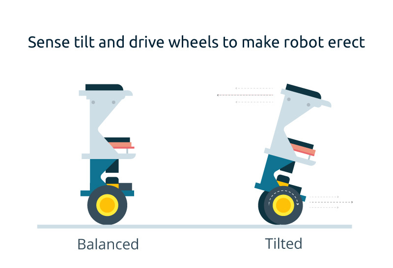
How Does Balancing Work?
To keep the robot balanced, the motors must counteract the fall of the robot. This action requires a feedback and a correcting element. The feedback element is the MPU6050 gyroscope + accelerometer, which gives both acceleration and rotation in all three axis (MPU6050 I2C basics) which is used by the Arduino to know the current orientation of the robot. The correcting element is the motor and wheel combination.
Required Materials
- Arduino (UNO or Nano can be used. I used Nano for this project.)
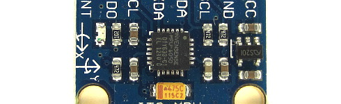
- MPU6050 gyro+accelerometer breakout board.
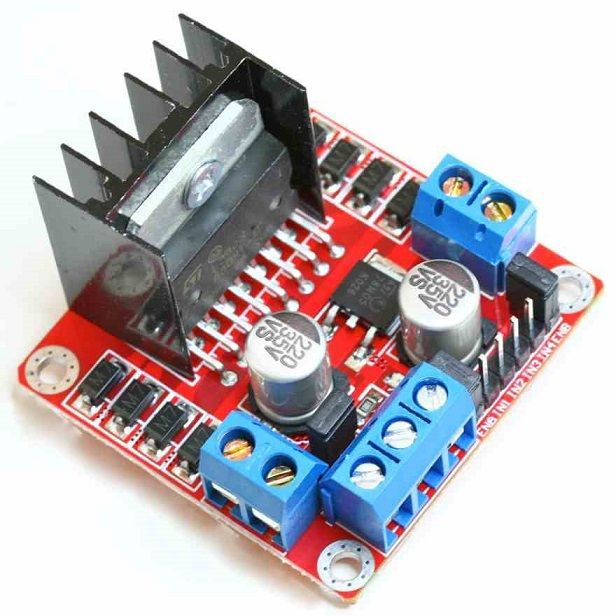
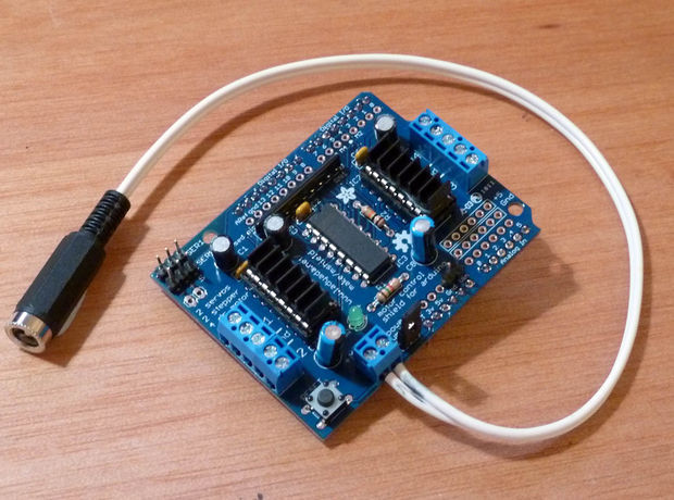
- L298N driver module
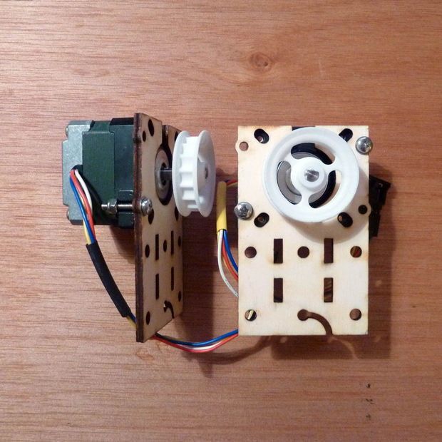
- 2 x Geared DC Motor+wheels
- Three platforms (PCB, acrylic, or thick plastic)
- Posts to hold the platforms
- Jumper wires
- Headers
- Battery Pack
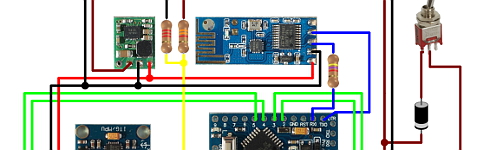
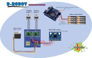
Connection Diagram
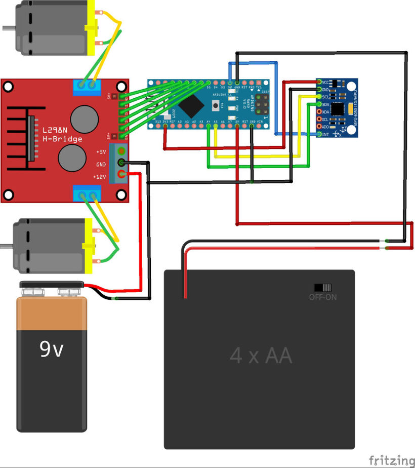
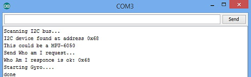
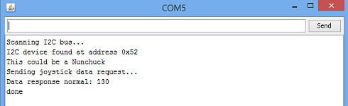
Connect the MPU6050 to the Arduino first and test the connection using the codes in this IMU interfacing tutorial. If data is now displayed on the serial monitor, you’re good to go! Proceed to connect the rest of the components as shown above.
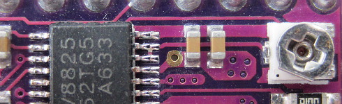
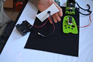
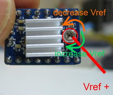
The L298N module can provide the +5V needed by the Arduino as long as its input voltage is +7 V or greater. However, I chose to have separate power sources for the motor and the circuit for isolation. Note that if you are planning to use a supply voltage of more than +12V for the L298N module, you need to remove the jumper just above the +12V input.
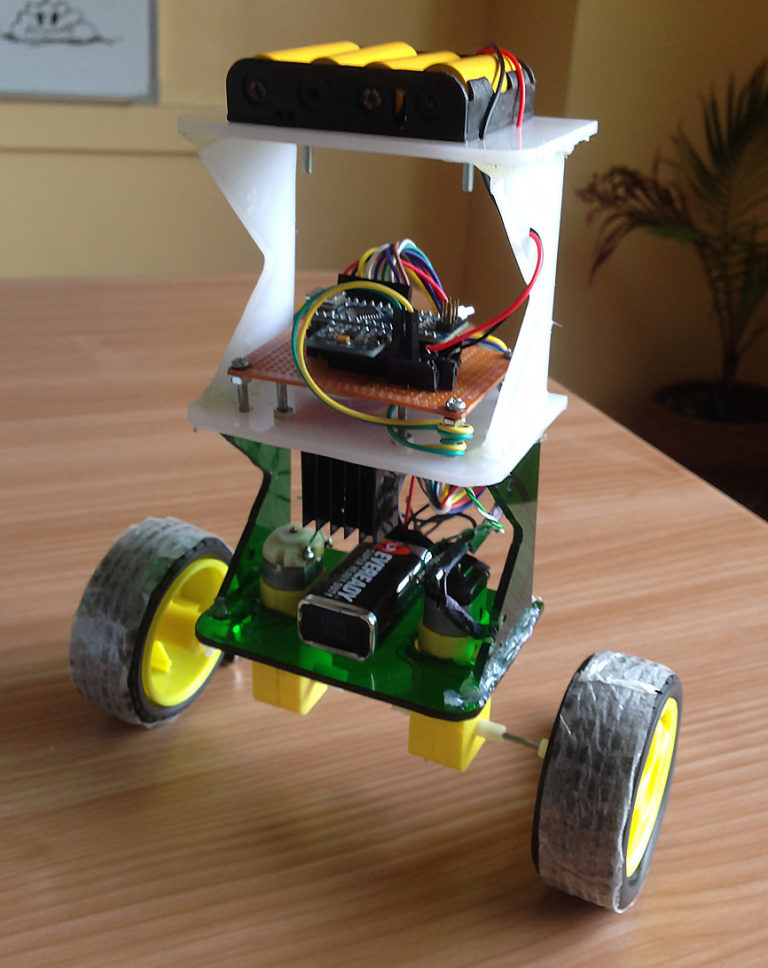
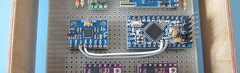
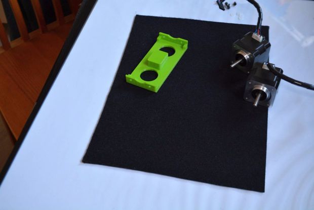
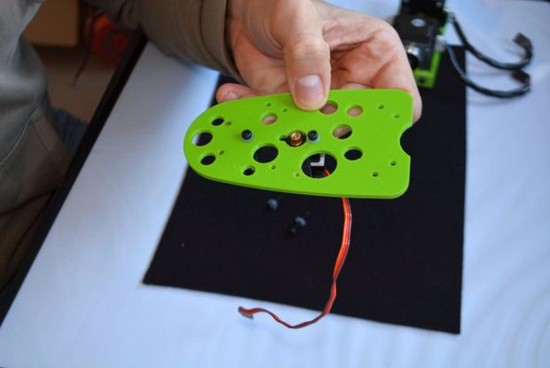
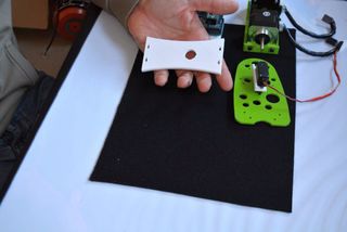
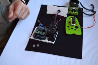
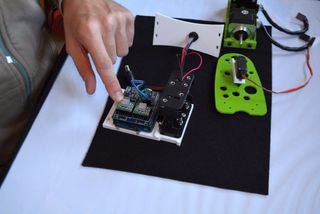
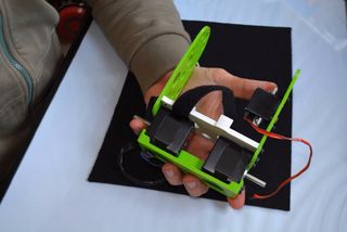
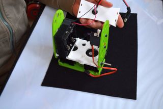
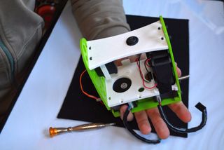
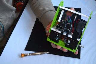
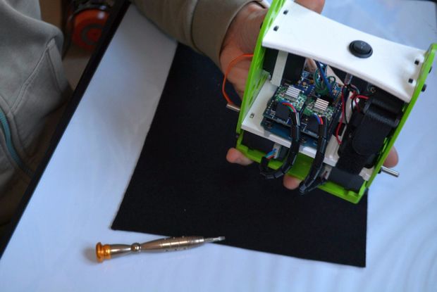
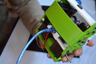
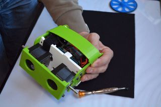
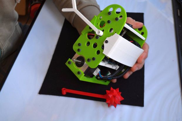
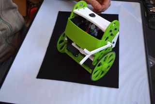
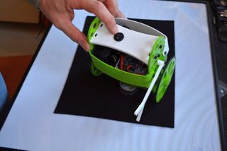
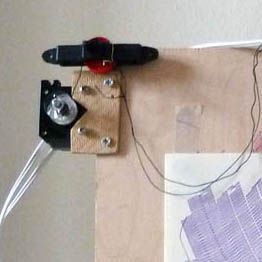
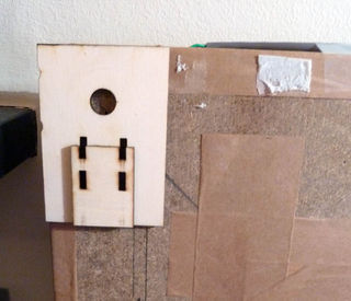
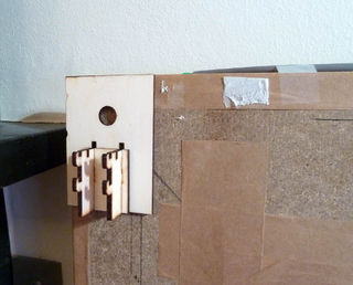
Building the Robot

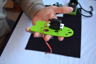
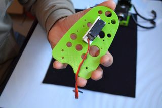
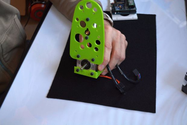
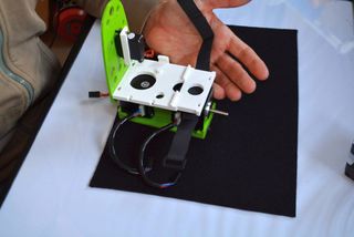
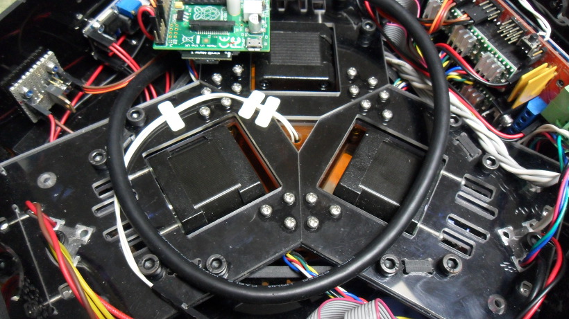
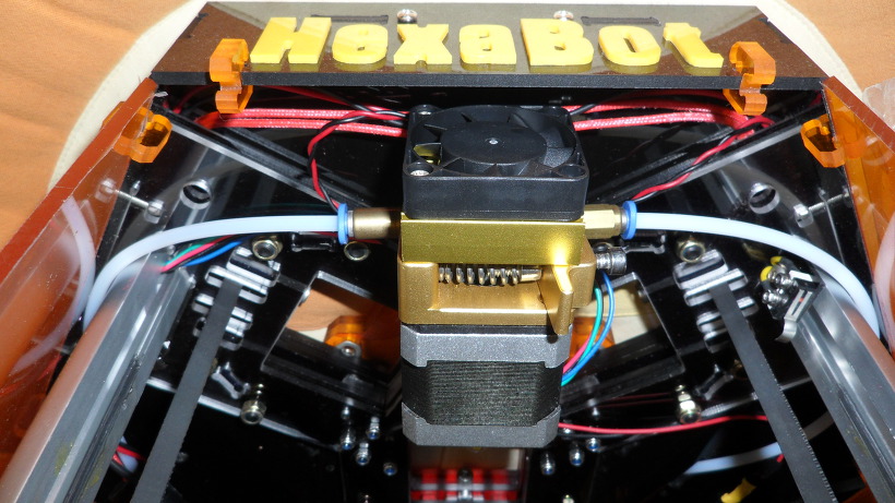
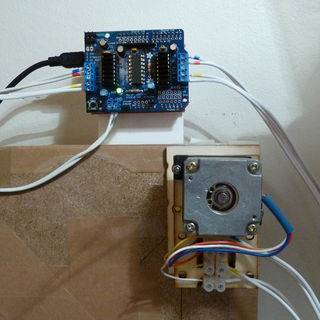
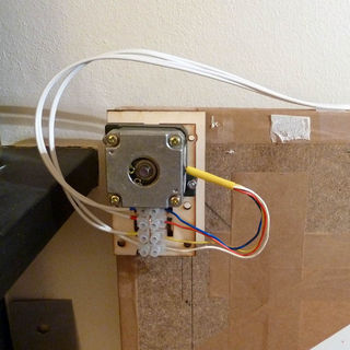
Robot frame (made mostly of acrylic slab) with two geared dc motors
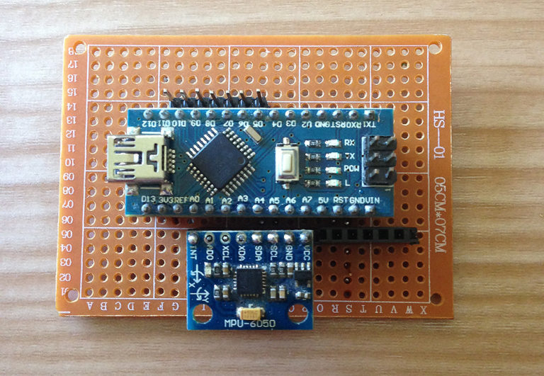
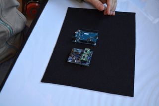
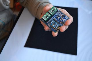
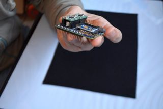
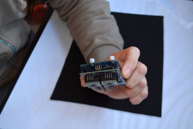
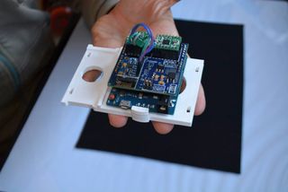
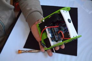
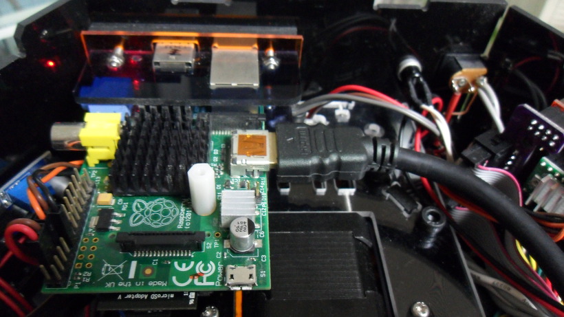
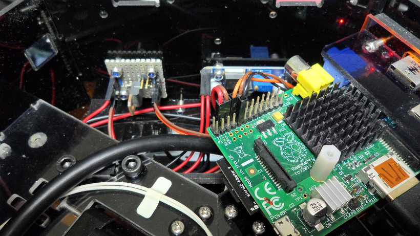
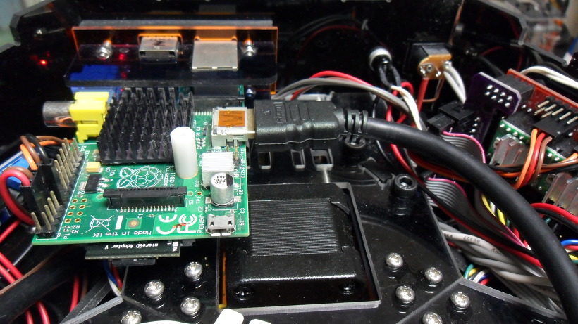
Main circuit board consisting of an Arduino Nano and MPU6050
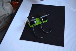
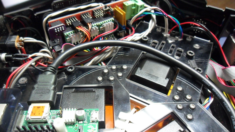
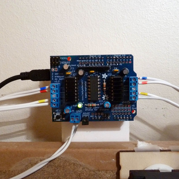
L298N motor driver module
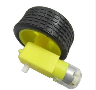
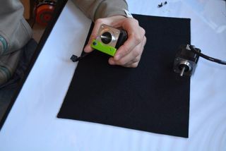
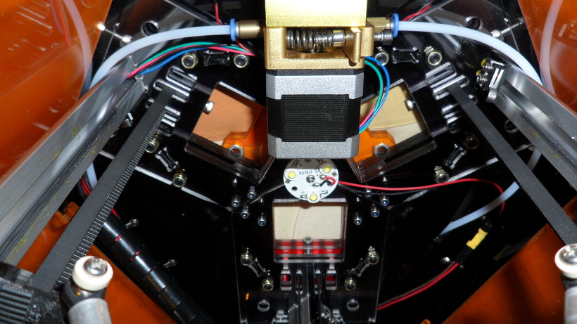
Geared DC motor with wheel
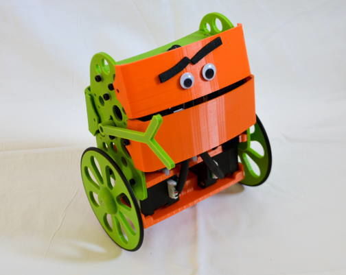
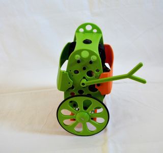
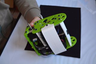
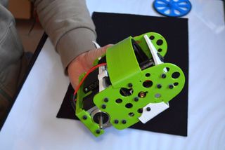
The self-balancing robot is essentially an inverted pendulum. It can be balanced better if the center of mass is higher relative to the wheel axles. A higher center of mass means a higher mass moment of inertia which corresponds to lower angular acceleration (slower fall). This is why I’ve placed the battery pack on top. The height of the robot, however, was chosen based on the availability of materials.
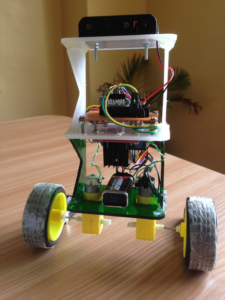
Completed self-balancing robot. At the top are six Ni-Cd batteries for powering the circuit board. In between the motors is a 9V battery for the motor driver.
More Self-balancing Theories
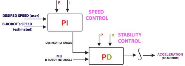
In control theory, keeping some variable (in this case, the position of the robot) steady needs a special controller called a PID: P for proportional, I for integral, and D for derivative. Each of these parameters has “gains” normally called Kp, Ki, and Kd.
PID provides correction between the desired value (or input) and the actual value (or output). The difference between the input and the output is called “error”. The PID controller reduces the error to the smallest value possible by continually adjusting the output. In our Arduino self-balancing robot, the input (which is the desired tilt, in degrees) is set by software. The MPU6050 reads the current tilt of the robot and feeds it to the PID algorithm which performs calculations to control the motor and keep the robot in the upright position.
PID requires that the gains Kp, Ki, and Kd values be “tuned” to optimal values. Engineers use software like MATLAB to compute these values automatically. Unfortunately, we can’t use MATLAB in our case because it would further complicate the project. We will tune the PID values manually instead. I’ve outlined the steps on how to do this:
-
- Make Kp, Ki, and Kd equal to zero.
- Adjust Kp. Too little Kp will make the robot fall over (not enough correction). Too much Kp will make the robot go back and forth wildly. A good enough Kp will make the robot slightly go back and forth (or oscillate a little).
- Once the Kp is set, adjust Kd. A good Kd value will lessen the oscillations until the robot is almost steady. Also, the right amount of Kd will keep the robot standing even if pushed.
- Lastly, set the Ki. The robot will oscillate when turned on even if the Kp and Kd are set but will stabilize in time. The correct Ki value will shorten the time it takes for the robot to stabilize.
Arduino Self-balancing Robot Code
I needed four external libraries to make this Arduino self-balancing robot work. The PID library makes it easy to calculate the P, I, and D values. The LMotorController library is used for driving the two motors with the L298N module. The I2Cdev library and MPU6050_6_Axis_MotionApps20 library are for reading data from the MPU6050. You can download the code including the libraries in this repository.
#include <PID_v1.h>
#include <LMotorController.h>
#include "I2Cdev.h"
#include "MPU6050_6Axis_MotionApps20.h"

#if I2CDEV_IMPLEMENTATION == I2CDEV_ARDUINO_WIRE
 #include "Wire.h"
#endif

#define MIN_ABS_SPEED 20

MPU6050 mpu;

// MPU control/status vars
bool dmpReady = false; // set true if DMP init was successful
uint8_t mpuIntStatus; // holds actual interrupt status byte from MPU
uint8_t devStatus; // return status after each device operation (0 = success, !0 = error)
uint16_t packetSize; // expected DMP packet size (default is 42 bytes)
uint16_t fifoCount; // count of all bytes currently in FIFO
uint8_t fifoBuffer[64]; // FIFO storage buffer

// orientation/motion vars
Quaternion q; // [w, x, y, z] quaternion container
VectorFloat gravity; // [x, y, z] gravity vector
float ypr[3]; // [yaw, pitch, roll] yaw/pitch/roll container and gravity vector

//PID
double originalSetpoint = 173;
double setpoint = originalSetpoint;
double movingAngleOffset = 0.1;
double input, output;

//adjust these values to fit your own design
double Kp = 50;
double Kd = 1.4;
double Ki = 60;
PID pid(&input, &output, &setpoint, Kp, Ki, Kd, DIRECT);

double motorSpeedFactorLeft = 0.6;
double motorSpeedFactorRight = 0.5;
//MOTOR CONTROLLER
int ENA = 5;
int IN1 = 6;
int IN2 = 7;
int IN3 = 8;
int IN4 = 9;
int ENB = 10;
LMotorController motorController(ENA, IN1, IN2, ENB, IN3, IN4, motorSpeedFactorLeft, motorSpeedFactorRight);

volatile bool mpuInterrupt = false; // indicates whether MPU interrupt pin has gone high
void dmpDataReady()
{
 mpuInterrupt = true;
}


void setup()
{
 // join I2C bus (I2Cdev library doesn't do this automatically)
 #if I2CDEV_IMPLEMENTATION == I2CDEV_ARDUINO_WIRE
 Wire.begin();
 TWBR = 24; // 400kHz I2C clock (200kHz if CPU is 8MHz)
 #elif I2CDEV_IMPLEMENTATION == I2CDEV_BUILTIN_FASTWIRE
 Fastwire::setup(400, true);
 #endif

 mpu.initialize();

 devStatus = mpu.dmpInitialize();

 // supply your own gyro offsets here, scaled for min sensitivity
 mpu.setXGyroOffset(220);
 mpu.setYGyroOffset(76);
 mpu.setZGyroOffset(-85);
 mpu.setZAccelOffset(1788); // 1688 factory default for my test chip

 // make sure it worked (returns 0 if so)
 if (devStatus == 0)
 {
 // turn on the DMP, now that it's ready
 mpu.setDMPEnabled(true);

 // enable Arduino interrupt detection
 attachInterrupt(0, dmpDataReady, RISING);
 mpuIntStatus = mpu.getIntStatus();

 // set our DMP Ready flag so the main loop() function knows it's okay to use it
 dmpReady = true;

 // get expected DMP packet size for later comparison
 packetSize = mpu.dmpGetFIFOPacketSize();

 //setup PID
 pid.SetMode(AUTOMATIC);
 pid.SetSampleTime(10);
 pid.SetOutputLimits(-255, 255);
 }
 else
 {
 // ERROR!
 // 1 = initial memory load failed
 // 2 = DMP configuration updates failed
 // (if it's going to break, usually the code will be 1)
 Serial.print(F("DMP Initialization failed (code "));
 Serial.print(devStatus);
 Serial.println(F(")"));
 }
}


void loop()
{
 // if programming failed, don't try to do anything
 if (!dmpReady) return;

 // wait for MPU interrupt or extra packet(s) available
 while (!mpuInterrupt && fifoCount < packetSize)
 {
 //no mpu data - performing PID calculations and output to motors
 pid.Compute();
 motorController.move(output, MIN_ABS_SPEED);

 }

 // reset interrupt flag and get INT_STATUS byte
 mpuInterrupt = false;
 mpuIntStatus = mpu.getIntStatus();

 // get current FIFO count
 fifoCount = mpu.getFIFOCount();

 // check for overflow (this should never happen unless our code is too inefficient)
 if ((mpuIntStatus & 0x10) || fifoCount == 1024)
 {
 // reset so we can continue cleanly
 mpu.resetFIFO();
 Serial.println(F("FIFO overflow!"));

 // otherwise, check for DMP data ready interrupt (this should happen frequently)
 }
 else if (mpuIntStatus & 0x02)
 {
 // wait for correct available data length, should be a VERY short wait
 while (fifoCount < packetSize) fifoCount = mpu.getFIFOCount();

 // read a packet from FIFO
 mpu.getFIFOBytes(fifoBuffer, packetSize);

 // track FIFO count here in case there is > 1 packet available
 // (this lets us immediately read more without waiting for an interrupt)
 fifoCount -= packetSize;

 mpu.dmpGetQuaternion(&q, fifoBuffer);
 mpu.dmpGetGravity(&gravity, &q);
 mpu.dmpGetYawPitchRoll(ypr, &q, &gravity);
 input = ypr[1] * 180/M_PI + 180;
 }
}
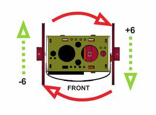
My Kp, Ki, Kd values may or may not work you. If it doesn’t, then follow the steps I outlined above. Notice that the input tilt in my code is set to 173 degrees. You can change this value if you’d like but take note that this is the tilt angle to which the robot must be maintained.
Also, if your motors are too fast, you can adjust the motorSpeedFactorLeft and motorSpeedFactorRight values.
Video
Here’s the self-balancing robot in action!
What’s Next?
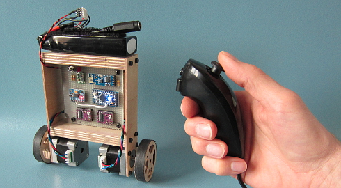
An improvement for this self-balancing robot would be controlling it remotely. Unfortunately, I can’t make this robot do that unless I make it ultra stable using dc motors with an encoder. An encoder would update the current speed of the motor which I can use to make the robot steadier via a second PID loop. I might do that next time so stay tuned!
 Q&A page


