Low-Cost, Arduino-Compatible Drawing Robot

I designed this project for a 10-hour workshop for ChickTech.org whose goal is to introduce teenage women to STEM topics. The goals for this project were:

  • Easy to build.
  • Easy to program.
  • Did something interesting.
  • Low-cost so participants could take it home and continue to learn.

With those goals in mind, here were a couple of the design choices:

  • Arduino compatible for ease of programming.
  • 4xAA battery power for cost and availability.
  • Stepper motors for accurate motion.
  • 3D Printed for ease of customization.
  • Pen plotting with Turtle graphics for interesting output.
  • Open Source so you could make one of your own!

Here is the robot that came closest to what I wanted to do: http://mirobot.io. I don’t have a laser cutter and shipping from England was prohibitive. I do have a 3D printer, so I guess you can see where this is going . . .

Don’t let the lack of a 3D printer deter you. You can locate local hobbyists willing to help you out at https://www.3dhubs.com/.

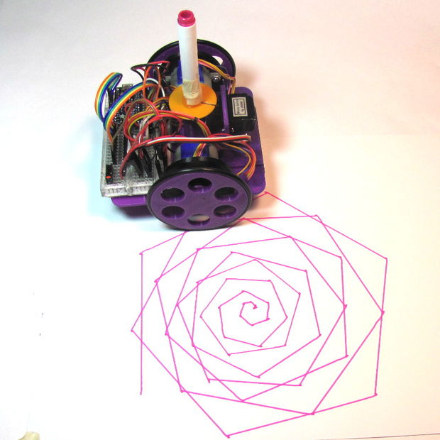
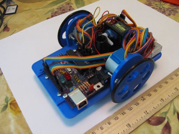
It took a lot of work, but I’m please with how it turned out. And, I learned quite a bit in the process. Let me know what you think!

Step 1: Parts

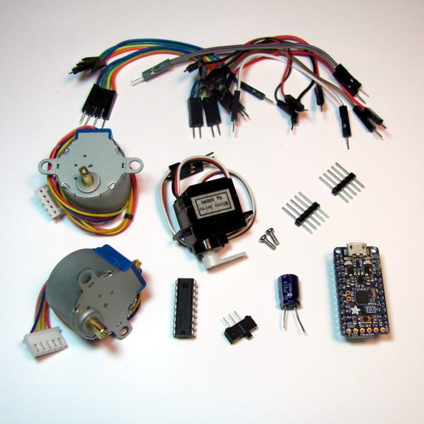
There are a number of ways to power, drive, and control robots. You may have different parts on hand that will work, but these are the ones I’ve tried and found to work well:

Electronics:

*Note: See the last step for a discussion on using regular Arduino or Raspberry Pi boards.

Hardware:

3D-Printed Parts (check out www.3dhubs.com if you don’t have access to a printer):

Tools and Supplies:

  • Phillips screw driver
  • Hot glue gun
  • Digital multi-meter
  • Sharp knife
  • Crayola colored markers

Step 2: Flash the Firmware

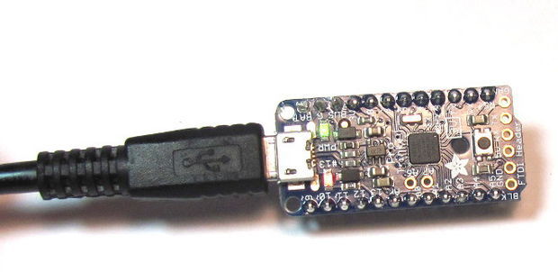
Before we get too far into construction, lets load the test firmware on to the microcontroller. The test program just draws for boxes so we can check for proper direction and dimension.

To talk to the Trinket Pro, you are going to need:

  1. Driver from https://learn.adafruit.com/introducing-pro-trinket…
  2. Arduino software from https://learn.adafruit.com/introducing-pro-trinket…

Lady Ada and the Adafruit team have created a far better set of instructions in the links above than I can provide. Please use them if you are stuck.

Note: The one trick that makes the Trinket different from regular Arduino is that you have to reset the board before uploading the sketch.

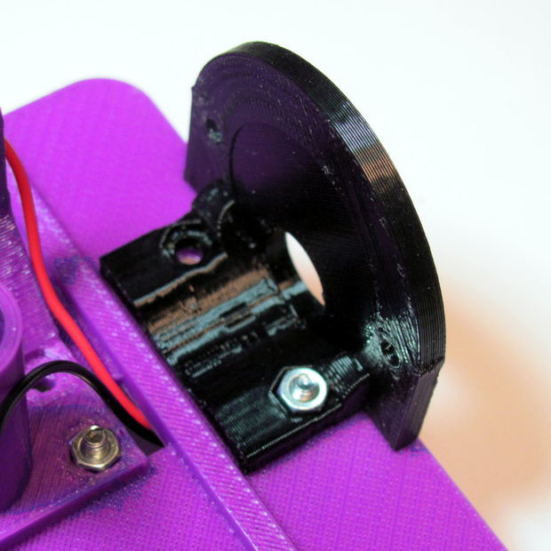
Step 3: Pen Holder and Battery Holders

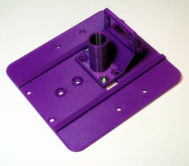
  1. Install the Pen Holder with the Servo Bracket on the shorter side of the chassis (Image 1).
  2. Insert the nuts on the top side of the chassis (Image 2)
  3. Attach the battery holders on the bottom of the chassis using 3Mx6mm flat-head screws (Images 3 & 4).
  4. Thread the battery leads through the rectangular cable runs (Image 4 & 5).
  5. Repeat for the other battery holder.

Note: Unless specified, the remainder of the screws are 3Mx8mm pan head srews.

Step 4: Wheels

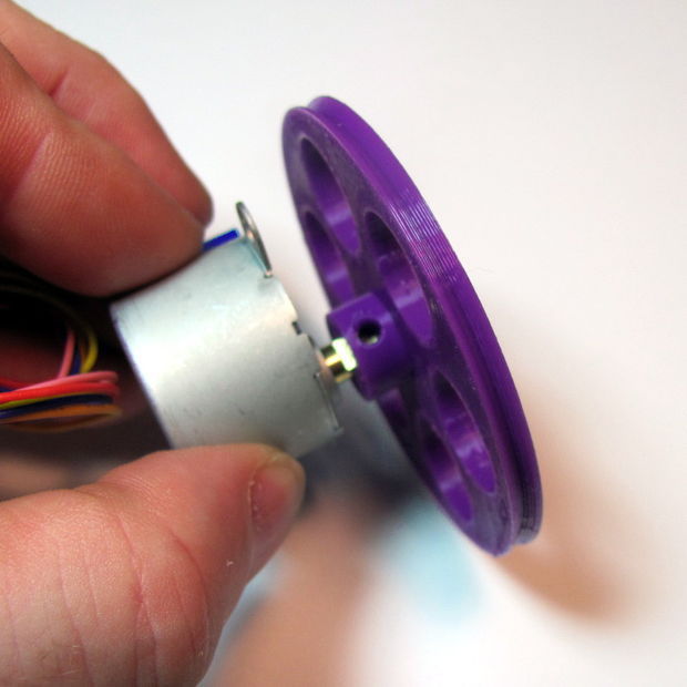
  1. Test fit your wheel to the stepper shaft (Image 1).
    1. If it is too tight, you can heat the wheel hub with a hair drier or hot air gun and then insert the shaft.
    2. If it is too loose, you can use a 3Mx8mm screw to hold it against the flat of the shaft (Image 2).
    3. If you are a perfectionist, you can calibrate your printer and get it just right.
  2. Place the o-ring around the rim of the wheel (Image 3 & 4).
  3. Repeat for the other wheel.

Step 5: Stepper Brackets

  1. Insert a nut into the stepper bracket and attach them to the top of the chassis with a screw (Image 1).
  2. Insert the stepper into the bracket and attach with screws and nuts.
  3. Repeat for the other bracket.

Step 6: Caster

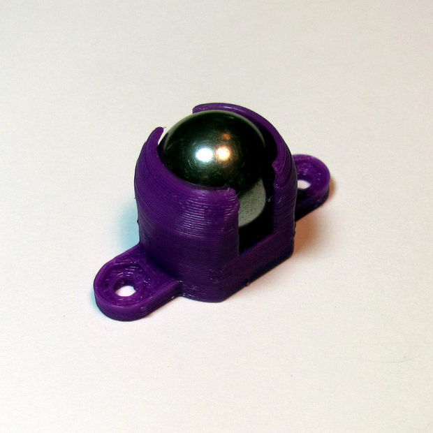
  1. Insert the ball bearing into the caster.
    • Do not force it in or it will break. Use a hair-drier or hot air gun to soften the material if needed.
  2. Attach the caster to the bottom side of the chassis in front of the battery holder.

Step 7: Breadboard

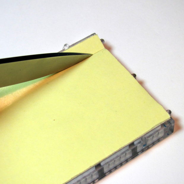
  1. Remove one of the power rails using a sharp knife, cutting through the bottom adhesive (Image 1).
  2. Holding the breadboard over the chassis rails, mark where they intersect the edge (Image 2).
  3. Using a straight edge (like the removed power rail), mark the lines and cut through the backing (Image 3).
  4. Place the breadboard on the chassis with the rails touching the exposed adhesive (Image 4).

Step 8: Power

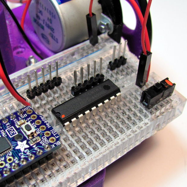
  1. Place the microcontroller, darlington driver, and power switch on to the bread board (Image 1).
    • I’ve added orange dots for visibility to mark the following:
      • Pin 1 of the darlington driver.
      • The battery pin of the microtroller.
      • The power switch “on” position.
  2. With the right-hand battery leads:
    1. Connect the red line to the first pin of the power switch (Image 2).
    2. Connect the black lead to an empty row between the microcontroller and the darlington chip (Image 2).
  3. With the left-hand battery leads:
    1. Connect the red line to the same row as the black lead of the other battery (Image 3).
    2. Connect the black line to the negative rail of the breadboard (Image 3).
  4. Connect power to the microcontroller:
    1. Red jumper from positive rail to the battery pin (orange dot, Image 4).
    2. Black jumper from the negative rail to the pin marked “G” (Image 4).
  5. Install batteries and switch the power on. You should see the green and red lights of the controller come on (Image 5).

Troubleshooting: If the microcontroller lights do not come on, immediately turn the power off and troubleshoot:

  1. Batteries installed in the correct orientation?
  2. Double check battery leads positioning.
  3. Double check switch leads positioning.
  4. Use a multi-meter to check voltages of batteries.
  5. Use multi-meter to check power rail voltages.

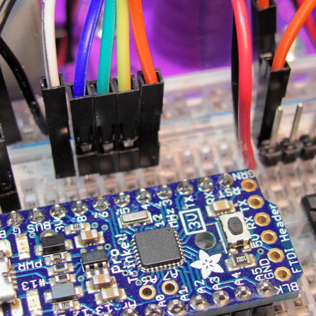
Step 9: Headers and Servo wiring

Male header pins allow us to connect the 5-pin servo JST connectors to power and the darlington driver (Image 1):

  1. The first 5-pin header starts one row in front of the darlington driver.
  2. The second servo header should then line up with the end of the darlington driver.

Before the wiring gets to complicated, lets get the servo wired up:

  1. Add a 3-pin header for the servo on the right edge of the forward section of the breadboard( Image 2).
  2. Add a red jumper from the center pin to the positive side of the power rail.
  3. Add a black or brown jumper from the outer pin to the negative side of the power rail.
  4. Add a colored jumper from the inner pin to Pin 8 of the microcontroller.
  5. Install the servo horn with the shaft to the full clock-wise position and the arm extending to the right-side wheel (Image 3)
  6. Install the servo in the pen holder using the servo’s screws (Image 3).
  7. Connect the servo connector aligning the colors (Image 4).

Step 10: Stepper Control

Time to wire power for the darlington driver and steppers, which will be driven directly from the battery:

  1. Connect a black or brown jumper from the lower right darlington pin to the negative side of the power rail (Image 1).
  2. Connect a red jumper from the upper right darlington pin to the positive side of the power rail.
  3. Connect a red jumper from the upper left pin header to the positive side of the power rail (Image 2).
  4. Connect the left stepper connector to the left side pin header with the red lead on the right side (Image 3).
  5. Connect the right stepper connector to the right side pin header with the read lead on the left side.

Note: The red lead of the stepper connector is the power and should match the red leads on the breadboard.

Step 11: Stepper Control (Continued)

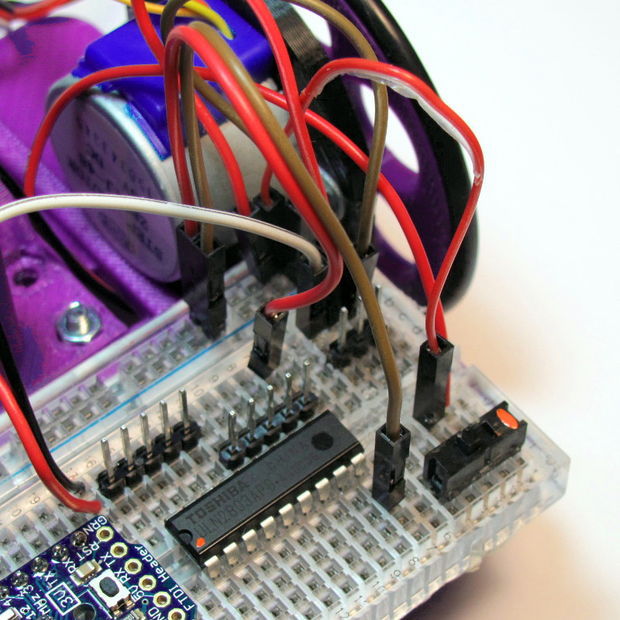
Now we will connect the stepper signal wires from the microcontroller to the input side of the darlington driver:

  1. Starting with Pin 6 of the microcontroller, connect the leads for four control jumpers for the left stepper motor (Image 1).
  2. Match these jumpers to the input side of the darlington on the right. All colors should match with the exception of green, which matches the pink wire of the stepper (Image 2).
  3. Starting with Pin 13 of the microcontroller, connect the leads for the four control jumpers for the right stepper motor (Image (3).
  4. Match these jumpers to the input side of the darlington on the left. All colors should match with the exception of green, which matches the pink wire of the stepper (Image 3).

Step 12: Testing and Calibration

Hopefully you already uploaded the firmware in Step 2. If not, do it now.

The test firmware just draws a square repeatedly so we can check direction and accuracy.

  1. Place your robot on a smooth, flat, open surface.
  2. Turn the power on.
  3. Watch your robot draw squares.

If you are not seeing lights on the microcontroller, go back and troublshoot power as in Step 8.

If your robot is not moving, double check the power connections to the darlington driver in Step 9.

If your robot is moving erratically, double check the pin connections for the microcontroller and darlington driver in Step 10.

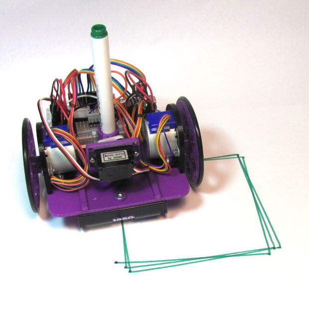
If your robot is moving in an approximate square, it is time to put some paper down and put a pen in it (Image 1).

Your calibration points are:

float wheel_dia=66.25;  // mm (increase = spiral out)
float wheel_base=112;   // mm (increase = spiral in)
int steps_rev=128;      // 128 for 16x gearbox, 512 for 64x gearbox

I started with a measured wheel diameter of 65 mm and you can see the boxes rotating inward (Image 2).

I increased the diameter to 67, and you can see it was rotating outward (Image 3).

I eventually arrived at a value of 66.25 mm (Image 4). You can see that there is still some inherent error due to gear lash and such. Close enough to do something interesting!

Step 13: Raising and lowering the pen

We’ve added a servo, but haven’t done anything with it. It allows you to raise and lower the pen so the robot can move without drawing.

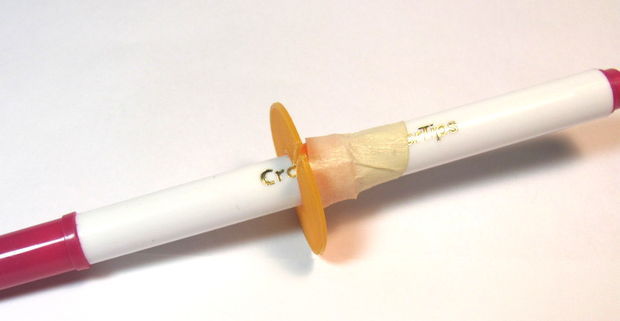
  1. Place the pen collar on the pen (Image 1).
  2. If it is loose, tape it in place.
  3. Check that it will touch the paper when the servo arm is lowered.
  4. Check that it will not touch the paper when raised (Image 2).

The servo angles can be adjusted either by removing the horn and re-positioning it, or through the software:

int PEN_DOWN = 170; // angle of servo when pen is down
int PEN_UP = 80;    // angle of servo when pen is up

The pen commands are:

penup();
pendown();

Step 14: Have Fun!

I hope you made is this far without too many curse words. Let me know what you struggled with so I can improve the instructions.

Now it is time to explore. If you look at the test sketch, you will see I have provided you some standard “Turtle” commands:

forward(distance);   // millimeters
backward(distance);
left(angle);         // degrees
right(angle);
penup();
pendown();
done();              // release stepper to save battery

Using these commands, you should be able to do just about anything, from drawing snow flakes or writing your name. If you need some help getting started, check out:

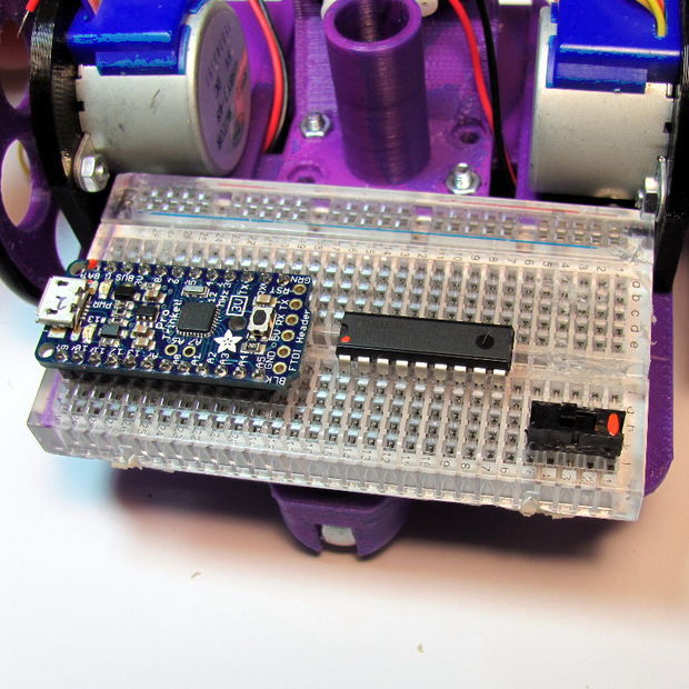
Step 15: Other Platforms

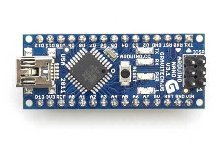
Could this robot be done with a regular Arduino? Yes! I went with the Trinket because of the low cost and small size. If you increase the chassis length, you can fit a regular Arduino on one side and the breadboard on the other (Image 1). It should work pin-for-pin with the test sketch, plus, you now can get to the serial console for debugging!

Could this robot be done with a Rasberry Pi? Yes! This was my first line of investigation because I wanted to program in Python, and be able to control it over the web. Like the full size Arduino above, you just place the Pi on one side, and the breadboard on the other (Image 2). Power becomes the primary concern because four AA is not going to cut it. You need to provide about 1A of current at a stable 5V, otherwise your WiFi module will stop communicating. I’ve found the Model A is much better on power consumption, but I’m still working out how to supply reliable power. If you figure it out, let me know!

Wii 리모컨(Wiimote)으로 RC Car 조종하기 – 2WS (Tamiya M-03)

이젠 벽돌이 되어버린 니텐도 Wii를 되살리기 차원에서 Wii 리모컨을 사용하여 RC Car를 조종하는 프로젝트를 시작해봅니다.

Source를 수정하여 Tamiya M-03 샤시에 적용해 보기로 했습니다.

Circuit@Home에서 소개 받았습니다!

RC car controlled by Wii Remote on Arduino http://www.circuitsathome.com/mcu/rc-car-controlled-by-wii-remote-on-arduino

USB Host를 적용하여 Bluetooth로 직접 연결하는 방식이기 때문에 구성은 매우 간단합니다.

Arduino는 Nano를 사용하였고 USB Host Shield와 연결하기 위해 Mother Board를 하나 꾸며보았습니다.

기능도 조금 추가했습니다.

바나나를 던지거나 하지는 못하지만 “A” 버튼을 누르면 레이저가 발사되듯이 Fire LED가 켜지도록 하였고 “+” 버튼은 Head Light, “-” 버튼은 Back Light로 사용할 수 있도록 하였습니다.

그리고 좌우방향 버튼으로도 Steering이 가능하도록 하였습니다.

 Arrow Up  Left steering
 Arrow Down  Right steering
 Arrow Left  Gear Down
 Arrow Right  Gear Up
 A  Fire & Shutting
 B  –
 +  Head Light
 –  Back Light
 1  Backward
 2  Forward
 Home  Throttle mode change

하드웨어 (Hardware)

송신기 (Transmitter)

  • Wii 리모컨 (Wiimote)

수신기 (Reciver)

  • Arduino Nano

  • USB Host Shield
  • Bluetooth USB 어댑터 (Dongle)

  • DIY Mother Board


통신 거리는 Bluetooth 특성상 대략 10m 정도 밖에 안될 거라고 예상합니다만 그 이상도 충분합니다.


RC Car

  • Tamiya M-03

소프트웨어 (Software)

Arduino 용 라이브러리와 스케치를 포함한 파일은 github 에 있습니다.
이 라이브러리는 Richard Ibbotson이 만든 코드 wiiblue.pde 을 기반으로하고 있습니다.

샘플 스케치 (Sketch)

TwoWheelSterringWii.ino

#include “WiiRemote.h”

#include <MemoryFree.h>

#include <Servo.h>

#define PIN_STEERING_SIGNAL        2

#define PIN_ESC_SIGNAL             4

#define PIN_HEAD_LIGHT_SIGNAL     14

#define PIN_BACK_LIGHT_SIGNAL     15

#define PIN_FIRE_SIGNAL           17

#define PIN_STEERING_SELECT       16

#define SERIAL_DEBUG               0    // 0: active mode, 1: serial debug mode

enum eAngle

{

STEERING_ANGLE_MAX           = 165,   // to right

STEERING_ANGLE_CENTER        = 90,

STEERING_ANGLE_MIN           = 15,    // to left

STEERING_ANGLE_STEP          = 5,

STEERING_ANGLE_MAX_INVERT    = 165,   // to right

STEERING_ANGLE_CENTER_INVERT = 90,

STEERING_ANGLE_MIN_INVERT    = 15,    // to left

THROTTLE_ANGLE_MAX           = 160,   // 80,

THROTTLE_ANGLE_CENTER        = 90,

THROTTLE_ANGLE_MIN           = 10,

};

enum eServoPulse

{

SERVO_PULSE_MAX              = 2400,  // to left

SERVO_PULSE_NEUTRAL          = 1550,  // 1500 Futaba compatible, 1.55msec

SERVO_PULSE_MIN              = 600,   // to right

SERVO_PULSE_MAX_INVERT       = 600,   // to right

SERVO_PULSE_NEUTRAL_INVERT   = 1450,  // 1460 Futaba compatible, 1.55msec

SERVO_PULSE_MIN_INVERT       = 2400,  // to left

};

enum eESCPulse

{

/*

*  Futaba timing

*

*  0us     1072us         1522us          1922us

*   +———*————+-*-+————-*

*   |   n/a   |   forwad   |d|d|   Reverse   |

*   +———*————+-*-+————-*

*          Max Forwad     Neutral         Max Reverse

*

*   d: dead zone, +10us and -10us

*/

ESC_PULSE_NEUTRAL     = 1522,

ESC_PULSE_BRAKE       = 1600,

ESC_PULSE_FWD_MAX     = 800,   //1200, // 1072

ESC_PULSE_FWD_MIN     = 1510,

ESC_PULSE_FWD_3RD     = (ESC_PULSE_FWD_MIN – 240),

ESC_PULSE_FWD_2ND     = (ESC_PULSE_FWD_MIN – 160),

ESC_PULSE_FWD_1ST     = (ESC_PULSE_FWD_MIN – 80),

ESC_PULSE_REV_MAX     = 1700,  // 1922

ESC_PULSE_REV_FIX     = 1650,

ESC_PULSE_REV_MIN     = 1600,

};

enum eGear

{

GEAR_1ST = 1,

GEAR_2ND = 2,

GEAR_3RD = 3,

};

WiiRemote wiiremote;

Servo SteeringServo;

Servo ESC;

void setup()

{

#if SERIAL_DEBUG

Serial.begin(115200);

Serial.print(“\r\nfreeMemory() reports: “);

Serial.print(freeMemory(), DEC);

Serial.println(“Serial connect…”);

#endif

SteeringServo.attach(PIN_STEERING_SIGNAL);

SteeringServo.writeMicroseconds(SERVO_PULSE_NEUTRAL);

ESC.attach(PIN_ESC_SIGNAL);

ESC.writeMicroseconds(ESC_PULSE_NEUTRAL);

pinMode(PIN_HEAD_LIGHT_SIGNAL, OUTPUT);

pinMode(PIN_BACK_LIGHT_SIGNAL, OUTPUT);

digitalWrite(PIN_HEAD_LIGHT_SIGNAL, LOW);

digitalWrite(PIN_BACK_LIGHT_SIGNAL, LOW);

pinMode(PIN_FIRE_SIGNAL, OUTPUT);

digitalWrite(PIN_FIRE_SIGNAL, LOW);

pinMode(PIN_STEERING_SELECT, INPUT);

digitalWrite(PIN_STEERING_SELECT, LOW);

wiiremote.init();

/*

unsigned char wiiremote_bdaddr[6] = {0x00, 0x1e, 0x35, 0xda, 0x48, 0xbc};

wiiremote.setBDAddress(wiiremote_bdaddr, 6);

wiiremote.setBDAddressMode(BD_ADDR_FIXED);

*/

#if SERIAL_DEBUG

Serial.println(“Wiimote connecting…”);

Serial.println(“Please press 1 button and 2 button simultaneously”);

#endif

}

void loop()

{

wiiremote.task(&myapp);

}

int steering_angle          = STEERING_ANGLE_CENTER;

int steering_angle_invert   = STEERING_ANGLE_CENTER_INVERT;

int old_steering_angle      = STEERING_ANGLE_CENTER;

bool analog_throttle        = false;  // false = use “One” button as throttle

int throttle_angle          = THROTTLE_ANGLE_CENTER;

int gear                    = GEAR_1ST;

int pulse_steering;

int pulse_esc;

bool fire                   = false;                  // fire

bool head_light             = false;                  // head light

bool back_light             = false;                  // back light

void myapp(void)

{

#if SERIAL_DEBUG

Serial.print(“\r\n”);

#endif

/* Steering */

steering_angle = getSteeringAngle();

steering_angle_invert = getSteeringAngleInvert();

if (digitalRead(PIN_STEERING_SELECT) == HIGH) {

pulse_steering = map(steering_angle,

STEERING_ANGLE_MIN, STEERING_ANGLE_MAX,

SERVO_PULSE_MAX, SERVO_PULSE_MIN);

SteeringServo.writeMicroseconds(pulse_steering);

} else {

pulse_steering = map(steering_angle_invert,

STEERING_ANGLE_MIN_INVERT, STEERING_ANGLE_MAX_INVERT,

SERVO_PULSE_MAX_INVERT, SERVO_PULSE_MIN_INVERT);

SteeringServo.writeMicroseconds(pulse_steering);

}

if (wiiremote.buttonPressed(WIIREMOTE_UP)) {

steering_angle = STEERING_ANGLE_MIN;

steering_angle_invert = STEERING_ANGLE_MIN_INVERT;

if (digitalRead(PIN_STEERING_SELECT) == HIGH) {

pulse_steering = map(steering_angle, STEERING_ANGLE_MIN, STEERING_ANGLE_MAX, SERVO_PULSE_MAX, SERVO_PULSE_MIN);

SteeringServo.writeMicroseconds(pulse_steering);

} else {

pulse_steering = map(steering_angle_invert, STEERING_ANGLE_MIN_INVERT, STEERING_ANGLE_MAX_INVERT, SERVO_PULSE_MAX_INVERT, SERVO_PULSE_MIN_INVERT);

SteeringServo.writeMicroseconds(pulse_steering);

}

} else if (wiiremote.buttonPressed(WIIREMOTE_DOWN)) {

steering_angle = STEERING_ANGLE_MAX;

steering_angle_invert = STEERING_ANGLE_MAX_INVERT;

if (digitalRead(PIN_STEERING_SELECT) == HIGH) {

pulse_steering = map(steering_angle, STEERING_ANGLE_MIN, STEERING_ANGLE_MAX, SERVO_PULSE_MAX, SERVO_PULSE_MIN);

SteeringServo.writeMicroseconds(pulse_steering);

} else {

pulse_steering = map(steering_angle_invert, STEERING_ANGLE_MIN_INVERT, STEERING_ANGLE_MAX_INVERT, SERVO_PULSE_MAX_INVERT, SERVO_PULSE_MIN_INVERT);

SteeringServo.writeMicroseconds(pulse_steering);

}

}

#if SERIAL_DEBUG

Serial.print(“\tServo=”);

Serial.print(pulse_steering);

#endif

/* Brake and Throttle */

if (wiiremote.buttonPressed(WIIREMOTE_ONE)) {

if (pulse_esc < ESC_PULSE_NEUTRAL) {

// moving forward before press “One”

brake();

pulse_esc = ESC_PULSE_NEUTRAL;

} else {

// while stopping or moving backward, keep moving backward

pulse_esc = ESC_PULSE_REV_FIX;

}

} else {

if (analog_throttle) {

throttle_angle = getThrottleAngle();

pulse_esc = map(throttle_angle,

THROTTLE_ANGLE_MIN, THROTTLE_ANGLE_MAX,

ESC_PULSE_FWD_MIN, ESC_PULSE_FWD_MAX);

} else if (wiiremote.buttonPressed(WIIREMOTE_TWO)) {

switch (gear) {

case GEAR_1ST:

pulse_esc = ESC_PULSE_FWD_1ST;

break;

case GEAR_2ND:

pulse_esc = ESC_PULSE_FWD_2ND;

break;

case GEAR_3RD:

pulse_esc = ESC_PULSE_FWD_3RD;

break;

default:

pulse_esc = ESC_PULSE_NEUTRAL;

break;

}

} else {

pulse_esc = ESC_PULSE_NEUTRAL;

}

}

ESC.writeMicroseconds(pulse_esc);

//delay(15);

#if SERIAL_DEBUG

Serial.print(“\tESC=”);

Serial.print(pulse_esc);

#endif

/* Throttle mode */

if (wiiremote.buttonClicked(WIIREMOTE_HOME)) {

analog_throttle = !analog_throttle;

if (analog_throttle) {

wiiremote.setLED(WIIREMOTE_LED4); // analog mode

} else {

wiiremote.setLED(WIIREMOTE_LED1); // fixed mode, 1st gear

gear = GEAR_1ST;

}

}

/* Shift up or down */

if (!analog_throttle) {

if (wiiremote.buttonClicked(WIIREMOTE_RIGHT)) {

shiftUp();

} else if (wiiremote.buttonClicked(WIIREMOTE_LEFT)) {

shiftDown();

}

}

/* Fire */

if (wiiremote.buttonPressed(WIIREMOTE_A)) {

digitalWrite(PIN_FIRE_SIGNAL, HIGH);

} else {

digitalWrite(PIN_FIRE_SIGNAL, LOW);

}

/* Head light LED */

if (wiiremote.buttonClicked(WIIREMOTE_PLUS)) {

head_light = !head_light;

if (head_light) {

digitalWrite(PIN_HEAD_LIGHT_SIGNAL, HIGH);

} else {

digitalWrite(PIN_HEAD_LIGHT_SIGNAL, LOW);

}

}

/* Back light LED */

if (wiiremote.buttonClicked(WIIREMOTE_MINUS)) {

back_light = !back_light;

if (back_light) {

digitalWrite(PIN_BACK_LIGHT_SIGNAL, HIGH);

} else {

digitalWrite(PIN_BACK_LIGHT_SIGNAL, LOW);

}

}

} // myapp

int getSteeringAngle(void)

{

double rad;

int deg;

rad = acos((double) wiiremote.Report.Accel.Y);

deg = (int) (rad * 180.0 / PI);

/* clipping */

if (deg > STEERING_ANGLE_MAX) { deg = STEERING_ANGLE_MAX; }

if (deg < STEERING_ANGLE_MIN) { deg = STEERING_ANGLE_MIN; }

return deg;

}

int getSteeringAngleInvert(void)

{

double rad;

int deg;

rad = acos((double) wiiremote.Report.Accel.Y);

deg = (int) (rad * 180.0 / PI);

/* clipping */

if (deg > STEERING_ANGLE_MAX_INVERT) { deg = STEERING_ANGLE_MAX_INVERT; }

if (deg < STEERING_ANGLE_MIN_INVERT) { deg = STEERING_ANGLE_MIN_INVERT; }

return deg;

}

int getThrottleAngle(void)

{

double rad;

double compensate_z;

int deg;

rad = asin((double) wiiremote.Report.Accel.Y);

compensate_z = (double) wiiremote.Report.Accel.Z / cos(rad);

rad = asin(compensate_z);

deg = (int) (rad * 180.0 / PI);

/* clipping */

if (deg > THROTTLE_ANGLE_MAX) { deg = THROTTLE_ANGLE_MAX; }

if (deg < THROTTLE_ANGLE_MIN) { deg = THROTTLE_ANGLE_MIN; }

return deg;

}

inline void brake(void)

{

ESC.writeMicroseconds(ESC_PULSE_BRAKE);

delay(15);

ESC.writeMicroseconds(ESC_PULSE_NEUTRAL);

delay(15);

}

inline void shiftUp(void)

{

if (gear < GEAR_3RD) {

gear++;

wiiremote.setLED( (WIIREMOTE_LED1 << (gear – GEAR_1ST)) );

}

}

inline void shiftDown(void)

{

if (gear > GEAR_1ST) {

gear–;

wiiremote.setLED( (WIIREMOTE_LED1 << (gear – GEAR_1ST)) );

}

}

Wii 리모컨(Wiimote)으로 RC Car 조종하기

이젠 벽돌이 되어버린 니텐도 Wii를 바라보다 갑자기 아깝다는 생각이 들어 폭풍 검색을 하다가 Wii 리모컨을 활용할 수 있는 괜찮은 소스를 찾은 것 같아 아래와 같이 소개 합니다.

잘~ 응용하면 재밋는 장난감이 되겠네요.

Circuit@Home에서 소개 받았습니다!

RC car controlled by Wii Remote on Arduino http://www.circuitsathome.com/mcu/rc-car-controlled-by-wii-remote-on-arduino

곳곳에서 Wii 리모컨을 사용한 재미있는 프로젝트를 볼 수 있습니다. PC에서 Bluetooth Stack를 이용한 프로젝트는 많은 있지만, PC를 사용하지 않고 마이컴 (AVR, PIC)에서 Bluetooth Stack를 이용한 프로젝트는 적은 것 같습니다. 그래서 (새삼 느낌입니다 만…) 마리오 카트를 조종하는 느낌으로 무선조종을 만들어 보았습니다. #바나나를 던지거나 하지는 않습니다.

하드웨어 (Hardware)

Arduino에서 Bluetooth Stack을 실현하여 무선조종서보와 ESC를 제어합니다.

송신기 (Transmitter)

  • Wii 리모컨 (Wiimote)

수신기 (Reciver)

  • Arduino
  • USB Host Shield
  • Bluetooth USB 어댑터 (Dongle)

통신 거리는 Bluetooth 특성상 대략 10m 정도 밖에 안될 거라고 예상합니다. 통신 거리를 늘리려면 XBee 등을 사용해야 할 것 입니다.

소프트웨어 (Software)

Arduino 용 라이브러리는 github 에 있습니다.
이 라이브러리는 Richard Ibbotson이 만든 코드 wiiblue.pde 을 기반으로하고 있습니다.
또한 이 라이브러리를 사용하기 위해서는, Oleg Mazurov가 개발 한 라이브러리 가 필요합니다.

샘플 스케치 (Sketch)


SterringWii.ino

#include "WiiRemote.h"
#include <MemoryFree.h>
#include <Servo.h>
#define PIN_STEERING_SIGNAL 2
#define PIN_ESC_SIGNAL  3
#define SERIAL_DEBUG 0
enum eAngle {
  STEERING_ANGLE_MAX    = 165,  // to right
  STEERING_ANGLE_MIN    = 15,   // to left
  STEERING_ANGLE_CENTER = 90,
  STEERING_ANGLE_STEP   = 5,
  THROTTLE_ANGLE_MAX    = 80,
  THROTTLE_ANGLE_MIN    = 10,
  THROTTLE_ANGLE_CENTER = 90,
};
enum eServoPulse {
  SERVO_PULSE_NEUTRAL = 1500, // Futaba compatible, 1.55msec
  SERVO_PULSE_MAX     = 1800, // to left
  SERVO_PULSE_MIN     = 1200, // to right
};
enum eESCPulse {
/*
 *  Futaba timing
 *
 *  0us     1072us         1522us          1922us
 *   +---------*------------+-*-+-------------*
 *   |   n/a   |   forwad   |d|d|   Reverse   |
 *   +---------*------------+-*-+-------------*
 *          Max Forwad     Neutral         Max Reverse
 *
 *   d: dead zone, +10us and -10us
 */
  ESC_PULSE_NEUTRAL = 1522,
  ESC_PULSE_BRAKE   = 1600,
  ESC_PULSE_FWD_MAX = 1200, // 1072
  ESC_PULSE_FWD_MIN = 1510,
  ESC_PULSE_FWD_3RD = (ESC_PULSE_FWD_MIN - 200),
  ESC_PULSE_FWD_2ND = (ESC_PULSE_FWD_MIN - 140),
  ESC_PULSE_FWD_1ST = (ESC_PULSE_FWD_MIN - 80),
  ESC_PULSE_REV_FIX = 1650,
  ESC_PULSE_REV_MAX = 1700, // 1922
  ESC_PULSE_REV_MIN = 1600,
};
enum eGear {
  GEAR_1ST = 1,
  GEAR_2ND = 2,
  GEAR_3RD = 3,
};
WiiRemote wiiremote;
Servo SteeringServo;
Servo ESC;
void setup()
{
#if SERIAL_DEBUG
  Serial.begin(9600);
  Serial.print("\r\nfreeMemory() reports: ");
  Serial.print(freeMemory(), DEC);
#endif
  SteeringServo.attach(PIN_STEERING_SIGNAL);
  SteeringServo.writeMicroseconds(SERVO_PULSE_NEUTRAL);
  ESC.attach(PIN_ESC_SIGNAL);
  ESC.writeMicroseconds(ESC_PULSE_NEUTRAL);
  wiiremote.init();
  /*
  unsigned char wiiremote_bdaddr[6] = {0x00, 0x1e, 0x35, 0xda, 0x48, 0xbc};
  wiiremote.setBDAddress(wiiremote_bdaddr, 6);
  wiiremote.setBDAddressMode(BD_ADDR_FIXED);
  */
}
void loop()
{
  wiiremote.task(&myapp);
}
int steering_angle = STEERING_ANGLE_CENTER;
int old_steering_angle = STEERING_ANGLE_CENTER;
bool analog_throttle = false// false = use "One" button as throttle
int throttle_angle = THROTTLE_ANGLE_CENTER;
int gear = GEAR_1ST;
int pulse_steering;
int pulse_esc;
void myapp(void) {
#if SERIAL_DEBUG
  Serial.print("\r\n");
#endif
  /* Steering */
  steering_angle = getSteeringAngle();
  pulse_steering = map(steering_angle,
                       STEERING_ANGLE_MIN, STEERING_ANGLE_MAX,
                       SERVO_PULSE_MAX, SERVO_PULSE_MIN);
  SteeringServo.writeMicroseconds(pulse_steering);
  //delay(15);
  Serial.print("\tServo=");
  Serial.print(pulse_steering);
  /* Brake and Throttle */
  if (wiiremote.buttonPressed(WIIREMOTE_ONE)) {
    if (pulse_esc < ESC_PULSE_NEUTRAL) {
      // moving forward before press "One"
      brake();
      pulse_esc = ESC_PULSE_NEUTRAL;
    } else {
      // while stopping or moving backward, keep moving backward
      pulse_esc = ESC_PULSE_REV_FIX;
    }
  } else {
    if (analog_throttle) {
      throttle_angle = getThrottleAngle();
      pulse_esc = map(throttle_angle,
                      THROTTLE_ANGLE_MIN, THROTTLE_ANGLE_MAX,
                      ESC_PULSE_FWD_MIN, ESC_PULSE_FWD_MAX);
    } else if (wiiremote.buttonPressed(WIIREMOTE_TWO)) {
      switch (gear) {
       case GEAR_1ST:
        pulse_esc = ESC_PULSE_FWD_1ST;
        break;
       case GEAR_2ND:
        pulse_esc = ESC_PULSE_FWD_2ND;
        break;
       case GEAR_3RD:
        pulse_esc = ESC_PULSE_FWD_3RD;
        break;
       default:
        pulse_esc = ESC_PULSE_NEUTRAL;
        break;
      }
    } else {
      pulse_esc = ESC_PULSE_NEUTRAL;
    }
  }
  ESC.writeMicroseconds(pulse_esc);
  //delay(15);
  Serial.print("\tESC=");
  Serial.print(pulse_esc);
  /* Throttle mode */
  if (wiiremote.buttonClicked(WIIREMOTE_A)) {
    analog_throttle = !analog_throttle;
    if (analog_throttle) {
      wiiremote.setLED(WIIREMOTE_LED4); // analog mode
    } else {
      wiiremote.setLED(WIIREMOTE_LED1); // fixed mode, 1st gear
      gear = GEAR_1ST;
    }
  }
  /* Shift up or down */
  if (!analog_throttle) {
    if (wiiremote.buttonClicked(WIIREMOTE_RIGHT)) {
      shiftUp();
    } else if (wiiremote.buttonClicked(WIIREMOTE_LEFT)) {
      shiftDown();
    }
  }
} // myapp
int getSteeringAngle(void) {
  double rad;
  int deg;
  rad = acos((double) wiiremote.Report.Accel.Y);
  deg = (int) (rad * 180.0 / PI);
  /* clipping */
  if (deg > STEERING_ANGLE_MAX) { deg = STEERING_ANGLE_MAX; }
  if (deg < STEERING_ANGLE_MIN) { deg = STEERING_ANGLE_MIN; }
  return deg;
}
int getThrottleAngle(void) {
  double rad;
  double compensate_z;
  int deg;
    rad = asin((double) wiiremote.Report.Accel.Y);
    compensate_z = (double) wiiremote.Report.Accel.Z / cos(rad);
    rad = asin(compensate_z);
    deg = (int) (rad * 180.0 / PI);
  /* clipping */
  if (deg > THROTTLE_ANGLE_MAX) { deg = THROTTLE_ANGLE_MAX; }
  if (deg < THROTTLE_ANGLE_MIN) { deg = THROTTLE_ANGLE_MIN; }
  return deg;
}
inline void brake(void)
{
    ESC.writeMicroseconds(ESC_PULSE_BRAKE);
    delay(15);
    ESC.writeMicroseconds(ESC_PULSE_NEUTRAL);
    delay(15);
}
inline void shiftUp(void)
{
    if (gear < GEAR_3RD) {
        gear++;
        wiiremote.setLED( (WIIREMOTE_LED1 << (gear - GEAR_1ST)) );
    }
}
inline void shiftDown(void)
{
    if (gear > GEAR_1ST) {
        gear--;
        wiiremote.setLED( (WIIREMOTE_LED1 << (gear - GEAR_1ST)) );
    }
}