How to Build an Arduino Self-Balancing Robot

By Roland Pelayo

Ever wonder how Segways work? This tutorial will show you how to build an Arduino self-balancing robot that balances itself — just like a Segway!

How Does Balancing Work?

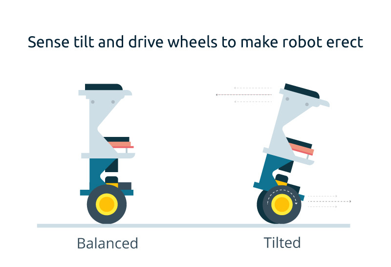
To keep the robot balanced, the motors must counteract the fall of the robot. This action requires a feedback and a correcting element. The feedback element is the MPU6050 gyroscope + accelerometer, which gives both acceleration and rotation in all three axis (MPU6050 I2C basics) which is used by the Arduino to know the current orientation of the robot. The correcting element is the motor and wheel combination.

Required Materials

  • Arduino (UNO or Nano can be used. I used Nano for this project.)
  • MPU6050 gyro+accelerometer breakout board.
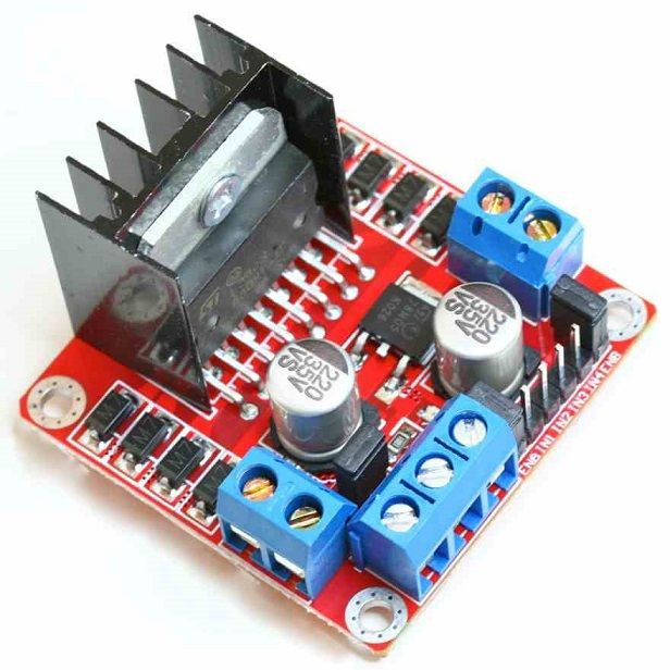
  • L298N driver module
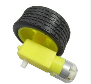
  • 2 x Geared DC Motor+wheels
  • Three platforms (PCB, acrylic, or thick plastic)
  • Posts to hold the platforms
  • Jumper wires
  • Headers
  • Battery Pack


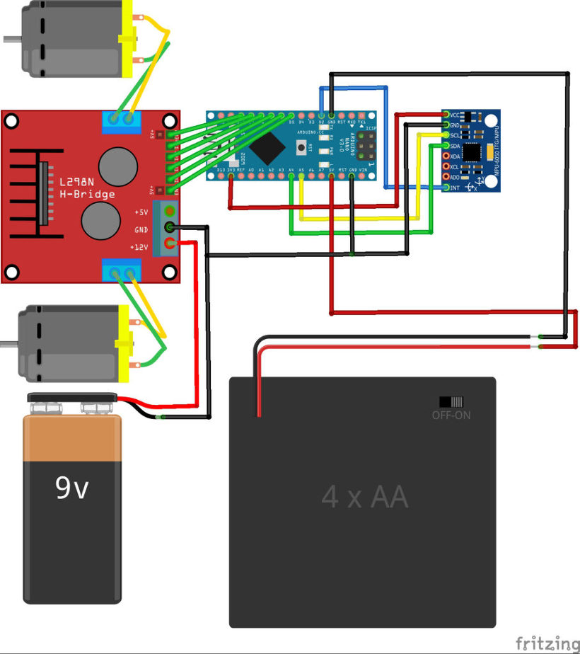
Connection Diagram

Complete Fritzing diagram

Connect the MPU6050 to the Arduino first and test the connection using the codes in this IMU interfacing tutorial.  If data is now displayed on the serial monitor, you’re good to go! Proceed to connect the rest of the components as shown above.

The L298N module can provide the +5V needed by the Arduino as long as its input voltage is +7 V or greater.  However, I chose to have separate power sources for the motor and the circuit for isolation. Note that if you are planning to use a supply voltage of more than +12V for the L298N module, you need to remove the jumper just above the +12V input.

Building the Robot

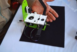
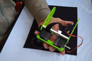
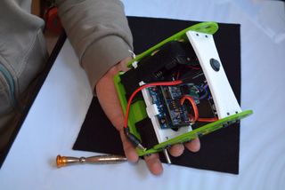
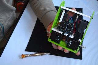
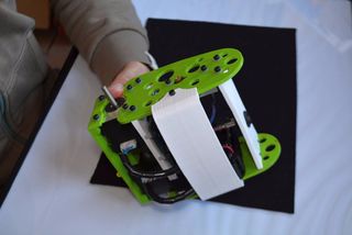
Robot frame (made mostly of acrylic slab) with two geared dc motors

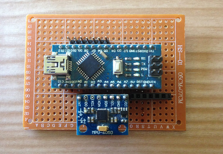
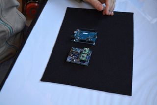
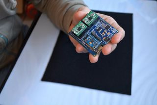
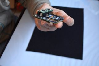
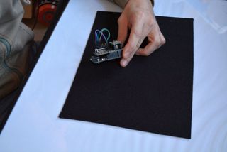
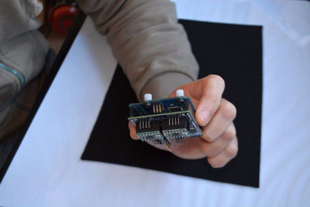
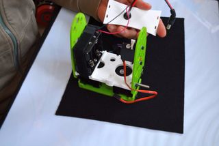
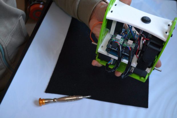
Main circuit board consisting of an Arduino Nano and MPU6050

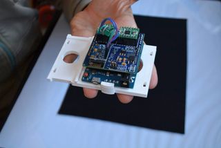
L298N motor driver module

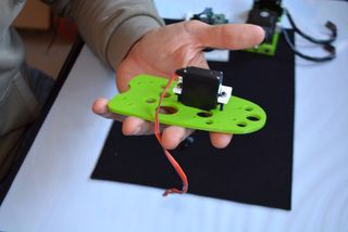
Geared DC motor with wheel


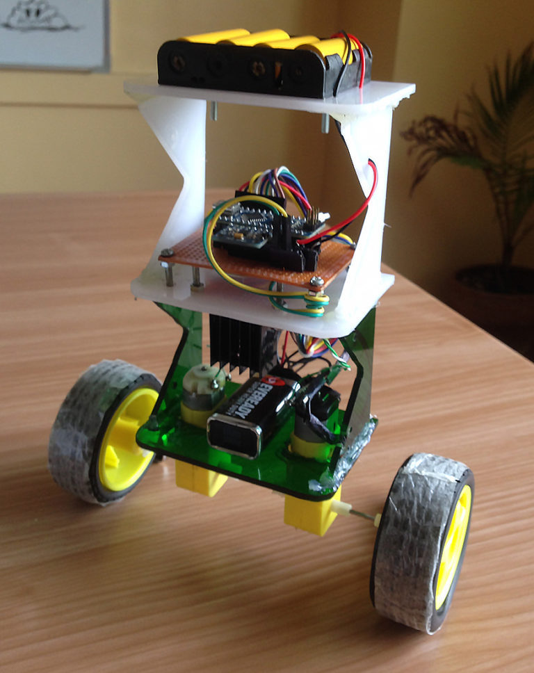
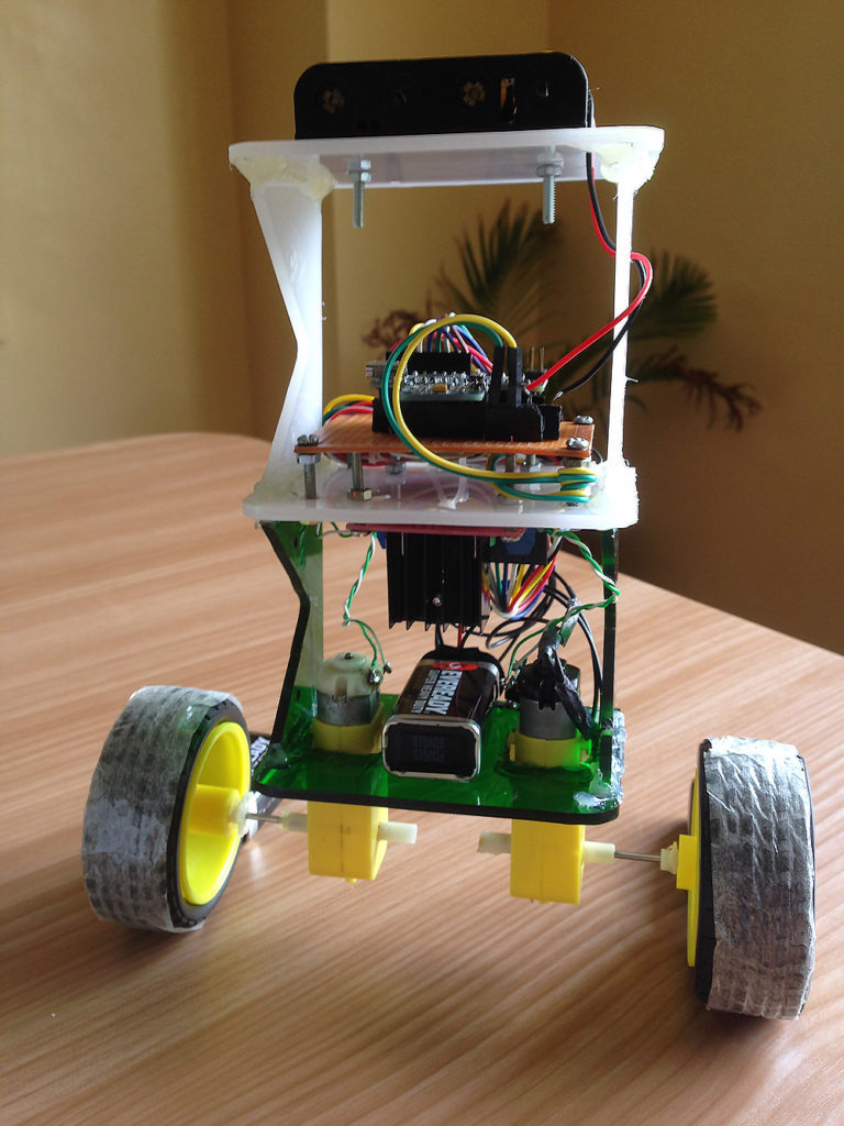
The self-balancing robot is essentially an inverted pendulum. It can be balanced better if the center of mass is higher relative to the wheel axles. A higher center of mass means a higher mass moment of inertia which corresponds to lower angular acceleration (slower fall). This is why I’ve placed the battery pack on top. The height of the robot, however, was chosen based on the availability of materials.

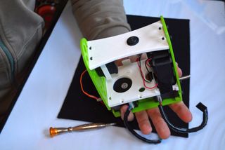
Completed self-balancing robot. At the top are six Ni-Cd batteries for powering the circuit board. In between the motors is a 9V battery for the motor driver.


More Self-balancing Theories

In control theory, keeping some variable (in this case, the position of the robot) steady needs a special controller called a PID: P for proportional, I for integral, and D for derivative. Each of these parameters has “gains” normally called Kp, Ki, and Kd.

PID provides correction between the desired value (or input) and the actual value (or output). The difference between the input and the output is called “error”. The PID controller reduces the error to the smallest value possible by continually adjusting the output. In our Arduino self-balancing robot, the input (which is the desired tilt, in degrees) is set by software. The MPU6050 reads the current tilt of the robot and feeds it to the PID algorithm which performs calculations to control the motor and keep the robot in the upright position.

PID requires that the gains Kp, Ki, and Kd values be “tuned” to optimal values. Engineers use software like MATLAB to compute these values automatically. Unfortunately, we can’t use MATLAB in our case because it would further complicate the project. We will tune the PID values manually instead. I’ve outlined the steps on how to do this:

    1. Make Kp, Ki, and Kd equal to zero.
    2. Adjust Kp. Too little Kp will make the robot fall over (not enough correction). Too much Kp will make the robot go back and forth wildly. A good enough Kp will make the robot slightly go back and forth (or oscillate a little).
    3. Once the Kp is set, adjust Kd. A good Kd value will lessen the oscillations until the robot is almost steady.  Also, the right amount of Kd will keep the robot standing even if pushed.
    4. Lastly, set the Ki. The robot will oscillate when turned on even if the Kp and Kd are set but will stabilize in time. The correct Ki value will shorten the time it takes for the robot to stabilize.


Arduino Self-balancing Robot Code

I needed four external libraries to make this Arduino self-balancing robot work. The PID library makes it easy to calculate the P, I, and D values. The LMotorController library is used for driving the two motors with the L298N module. The I2Cdev library and MPU6050_6_Axis_MotionApps20 library are for reading data from the MPU6050. You can download the code including the libraries in this repository.

#include <PID_v1.h>
#include <LMotorController.h>
#include "I2Cdev.h"
#include "MPU6050_6Axis_MotionApps20.h"

#if I2CDEV_IMPLEMENTATION == I2CDEV_ARDUINO_WIRE
 #include "Wire.h"
#endif

#define MIN_ABS_SPEED 20

MPU6050 mpu;

// MPU control/status vars
bool dmpReady = false; // set true if DMP init was successful
uint8_t mpuIntStatus; // holds actual interrupt status byte from MPU
uint8_t devStatus; // return status after each device operation (0 = success, !0 = error)
uint16_t packetSize; // expected DMP packet size (default is 42 bytes)
uint16_t fifoCount; // count of all bytes currently in FIFO
uint8_t fifoBuffer[64]; // FIFO storage buffer

// orientation/motion vars
Quaternion q; // [w, x, y, z] quaternion container
VectorFloat gravity; // [x, y, z] gravity vector
float ypr[3]; // [yaw, pitch, roll] yaw/pitch/roll container and gravity vector

//PID
double originalSetpoint = 173;
double setpoint = originalSetpoint;
double movingAngleOffset = 0.1;
double input, output;

//adjust these values to fit your own design
double Kp = 50;   
double Kd = 1.4;
double Ki = 60;
PID pid(&input, &output, &setpoint, Kp, Ki, Kd, DIRECT);

double motorSpeedFactorLeft = 0.6;
double motorSpeedFactorRight = 0.5;
//MOTOR CONTROLLER
int ENA = 5;
int IN1 = 6;
int IN2 = 7;
int IN3 = 8;
int IN4 = 9;
int ENB = 10;
LMotorController motorController(ENA, IN1, IN2, ENB, IN3, IN4, motorSpeedFactorLeft, motorSpeedFactorRight);

volatile bool mpuInterrupt = false; // indicates whether MPU interrupt pin has gone high
void dmpDataReady()
{
 mpuInterrupt = true;
}


void setup()
{
 // join I2C bus (I2Cdev library doesn't do this automatically)
 #if I2CDEV_IMPLEMENTATION == I2CDEV_ARDUINO_WIRE
 Wire.begin();
 TWBR = 24; // 400kHz I2C clock (200kHz if CPU is 8MHz)
 #elif I2CDEV_IMPLEMENTATION == I2CDEV_BUILTIN_FASTWIRE
 Fastwire::setup(400, true);
 #endif

 mpu.initialize();

 devStatus = mpu.dmpInitialize();

 // supply your own gyro offsets here, scaled for min sensitivity
 mpu.setXGyroOffset(220);
 mpu.setYGyroOffset(76);
 mpu.setZGyroOffset(-85);
 mpu.setZAccelOffset(1788); // 1688 factory default for my test chip

 // make sure it worked (returns 0 if so)
 if (devStatus == 0)
 {
 // turn on the DMP, now that it's ready
 mpu.setDMPEnabled(true);

 // enable Arduino interrupt detection
 attachInterrupt(0, dmpDataReady, RISING);
 mpuIntStatus = mpu.getIntStatus();

 // set our DMP Ready flag so the main loop() function knows it's okay to use it
 dmpReady = true;

 // get expected DMP packet size for later comparison
 packetSize = mpu.dmpGetFIFOPacketSize();
 
 //setup PID
 pid.SetMode(AUTOMATIC);
 pid.SetSampleTime(10);
 pid.SetOutputLimits(-255, 255); 
 }
 else
 {
 // ERROR!
 // 1 = initial memory load failed
 // 2 = DMP configuration updates failed
 // (if it's going to break, usually the code will be 1)
 Serial.print(F("DMP Initialization failed (code "));
 Serial.print(devStatus);
 Serial.println(F(")"));
 }
}


void loop()
{
 // if programming failed, don't try to do anything
 if (!dmpReady) return;

 // wait for MPU interrupt or extra packet(s) available
 while (!mpuInterrupt && fifoCount < packetSize)
 {
 //no mpu data - performing PID calculations and output to motors 
 pid.Compute();
 motorController.move(output, MIN_ABS_SPEED);
 
 }

 // reset interrupt flag and get INT_STATUS byte
 mpuInterrupt = false;
 mpuIntStatus = mpu.getIntStatus();

 // get current FIFO count
 fifoCount = mpu.getFIFOCount();

 // check for overflow (this should never happen unless our code is too inefficient)
 if ((mpuIntStatus & 0x10) || fifoCount == 1024)
 {
 // reset so we can continue cleanly
 mpu.resetFIFO();
 Serial.println(F("FIFO overflow!"));

 // otherwise, check for DMP data ready interrupt (this should happen frequently)
 }
 else if (mpuIntStatus & 0x02)
 {
 // wait for correct available data length, should be a VERY short wait
 while (fifoCount < packetSize) fifoCount = mpu.getFIFOCount();

 // read a packet from FIFO
 mpu.getFIFOBytes(fifoBuffer, packetSize);
 
 // track FIFO count here in case there is > 1 packet available
 // (this lets us immediately read more without waiting for an interrupt)
 fifoCount -= packetSize;

 mpu.dmpGetQuaternion(&q, fifoBuffer);
 mpu.dmpGetGravity(&gravity, &q);
 mpu.dmpGetYawPitchRoll(ypr, &q, &gravity);
 input = ypr[1] * 180/M_PI + 180;
 }
}

My Kp, Ki, Kd values may or may not work you. If it doesn’t, then follow the steps I outlined above. Notice that the input tilt in my code is set to 173 degrees. You can change this value if you’d like but take note that this is the tilt angle to which the robot must be maintained.

Also, if your motors are too fast, you can adjust the motorSpeedFactorLeft and motorSpeedFactorRight values.

Video

Here’s the self-balancing robot in action!

What’s Next?

An improvement for this self-balancing robot would be controlling it remotely. Unfortunately, I can’t make this robot do that unless I make it ultra stable using dc motors with an encoder. An encoder would update the current speed of the motor which I can use to make the robot steadier via a second PID loop. I might do that next time so stay tuned!

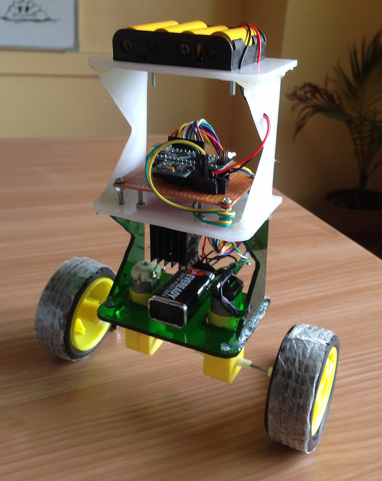
Your Arduino Balancing Robot (YABR)

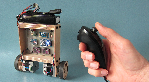
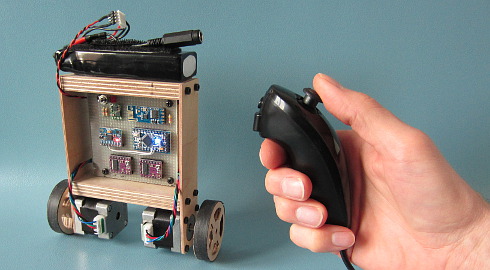
Your Arduino Balancing Robot (YABR) is a self-balancing robot that you can build yourself as a school project or as a fun project with your kids. It might look simple but there is a lot that you can learn from building this self-balancing robot.

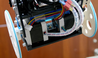
In contrast to most self-balancing robots, this one uses stepper motors instead of regular DC motors. The main reason is that stepper motors are precise and have no performance loss when the battery voltage drops. One pulse is always an exact amount of motion. Regular DC motors can have mechanical friction and electric resistance differences. This can cause performance differences. As a result the robot will not move in a straight line.

The total cost to build this robot is approximately $80 if you use the hardware list below. This includes a battery, Nunchuck, charger, stepper motors, etc.

The Arduino program that you can download for free is 100% self-written and not based on any other software. The code is well commented and clearly explained. This makes it possible to further develop the code for your own purpose.

 Click to see the full image

If you encounter any problems during the build or setup please check the Q&A page first. Most questions are already answered in detail.

Step 1 – Software

First download the complete YMFC-AL software package:

YABR.zip (version 1.1)

Step 2 – Hardware

To build this robot you need hardware. I made the following list for convenience purpose alone. You are free to get your own hardware from different sources. But this is the hardware that I used/ordered:

If the 35mm stepper motors are out of stock. You could also use these stepper motors. Please note that these are 42mm in stead of 35mm. So you have to modify the frame.

Most of the following parts can be found in your local electronics store. But in case you don’t have an electronics store nearby I will put links here:

And finally you need an old inner tube and two sheets of plywood. I used 2.5mm and 12.5mm sheets.

Step 3 – Tools

And of course you need some simple tools like a soldering iron, screwdrivers, a fretsaw, compact drill, etc.

Step 4 – The build

Watch the YABR hardware build video and build the robot according to the video and the schematic that is included in the complete software package.

Building the YABR balancing robot.

Detailed pictures of my own YABR balancing robot can be found in the media section of this project page.


4.1 The diode and resistors


The resistor R1 on the schematic is needed for uploading a program to the Arduino. The TXD output of the transceiver is forced high or low. As a result the FTDI programmer cannot change this output anymore and you will get an upload error. By adding this resistor the FTDI programmer can change the voltage on the RX-pin of the Arduino despite the state the transceiver output and the program is uploaded without any problems.

The other two resistors (R2 and R3) form a voltage divider. Meaning that the 12.6 volt of the battery minus the 0.6 volt voltage drop over the diode is divided by 2.5. Resulting in a 4.8 volt on the analog input when the battery fully charged. In the main program this analog input will be used to protect the battery. This is because lipo batteries can be damaged when the voltage drops below 3 volt per cell.

The diode D1 protects all the electronics against reversed polarity. So when you accidentally reverse the connections of the battery the components won’t go up in smoke.


4.2 The MPU-6050 gyro/accelerometer


The only gyro / accelerometer that is supported by the YABR software is the MPU-6050. This is because the self-level feature requires an accelerometer and a gyro as I explain in these two videos:

MPU-6050 6dof IMU tutorial for auto-leveling quadcopters – Part 1
MPU-6050 6dof IMU tutorial for auto-leveling quadcopters – Part 2

The orientation of the gyro is important. Make sure to mount the gyro in the exact same orientation as shown on this picture. Otherwise the YABR software cannot calculate the correct angle and the robot will not work.


4.3 Hardware test


Please note that you are soldering the wires on the back side of the PCB. The schematic is drawn facing the components from the front. So everything is mirrored and you need to double check all the connections before you connect any power to the PCB.

With everything in place it’s time to connect the FTDI programmer to the Arduino pro mini. Don’t connect the battery yet. If the LED’s don’t lit up there is a short circuit in the wiring and you need to disconnect the FTDI programmer as soon as possible. Normally the Arduino pro mini is already programmed with the blink sketch so the LED on the Arduino should start to flash.

To check if the gyro is connected correctly and to check the balancing point of the robot you need to upload the “hardware-check” program that you can find in the software package that you downloaded earlier.

Test the balancing angle of the robot and fix it in that position on a stand as I showed in the video. Upload the “hardware-check” program, open the serial monitor and set the baud rate to 9600.

After uploading the program, open the serial monitor and set the baud rate to 9600.

The program will check if there is any I2C device is connected and if this is a MPU-6050. If everything is working as expected the program will output several raw gyro values on the screen. These are just examples and your values may be different. Note down the balance value that you see in the serial output. You will need it later in the main program.


4.4 Limit the motor current


Next thing on the to do list is to set the stepper controllers to the correct drive current. If the motor current is set to high the stepper controllers will heat up and they might get damaged.

First set the potentiometer at the same position as shown in the picture below. Now always be careful when connecting the lipo battery for the first time. A short circuit can cause high currents, heat, sparks, and burns.

A good alternative is to use a small DC fuse like the one below. This fuse will blow if the wiring on the back side of the pcb holds a short circuit.

The easiest and safest way to set the correct current and to check if the wiring is correctly connected is by measuring the current in the power supply wires with a bench power supply. The power supply is limited to 500milli amps. This is an extra safety feature. If there is a short circuit the power supply will limit the current to 500 milli amps and the wiring will be fine.

First connect one motor. With the potentiometer it’s possible to set the current between 100 and 150mA. This is more than enough to get good performance. Do the same with the other stepper controller.

If you don’t have the possibility to measure the current just set the potentiometer in this position and feel if the stepper driver doesn’t get to hot. But it’s always best to measure the current.


3.5 The remote control


If you open the Nunchuck you can note the wire colors that are connected to the various pins as you can see on the schematic. The Nunchuck works on 3.3V and you can use the 3.3V output of the Arduino Uno to power the Nunchuck.

The 5V output can be used for the transceiver. Again, connect the wires as shown on the schematic to get it to work.

To check if the Nunchuck is connected correctly you need to upload the “hardware-check” program that you can find in the software package that you downloaded earlier. After uploading the program, open the serial monitor and set the baud rate to 9600.

The program will check if there is any I2C device is connected and if this is a Nunchuck. If everything is working as expected the program will output several raw joystick values on the screen.

Step 5 – Upload the software

And finally you can upload the YABR-remote program to the Arduino Uno and the YABR-robot program to the Arduino pro mini.

The YABR-remote program does not need any modification. In the robot program you need to change the accelerometer calibration value to the value that was shown by the hardware test program when the robot was in it’s balancing position.

To start the robot you need to power up the remote. Lay the robot on it’s back and switch on the power. The LED will blink indicating that the gyro is calibrating. When the blinking stops you can slowly lift the robot and it will automatically start to balance itself.

And basically that’s it. You can now control the robot with the Nunchuck.

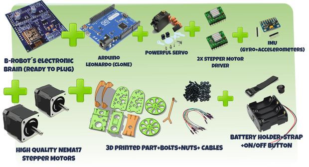
B-Robot EVO 2 KIT (Plug and Play Robot version)

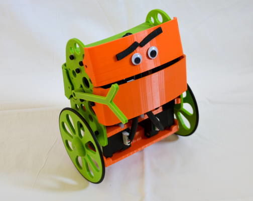
JJrobots´s B-ROBOT EVO 2 Kit. Created to simplify the set up and integration of all the different devices involved in this project.

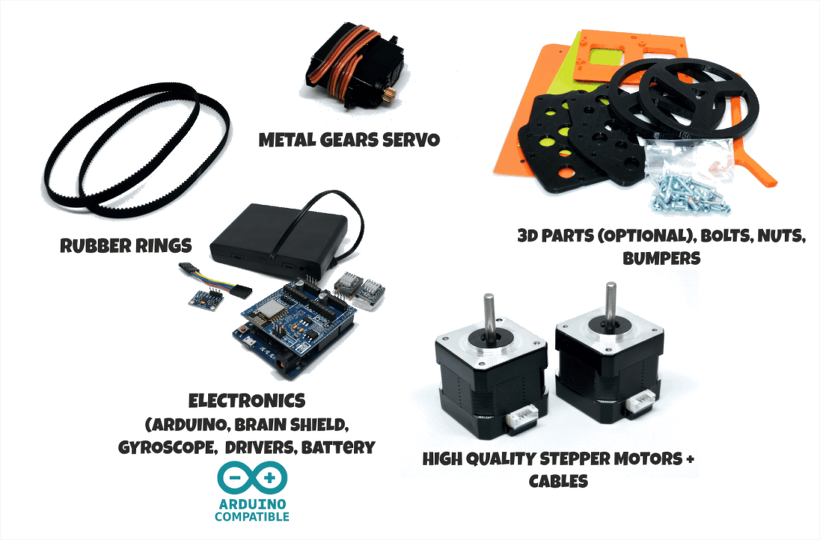
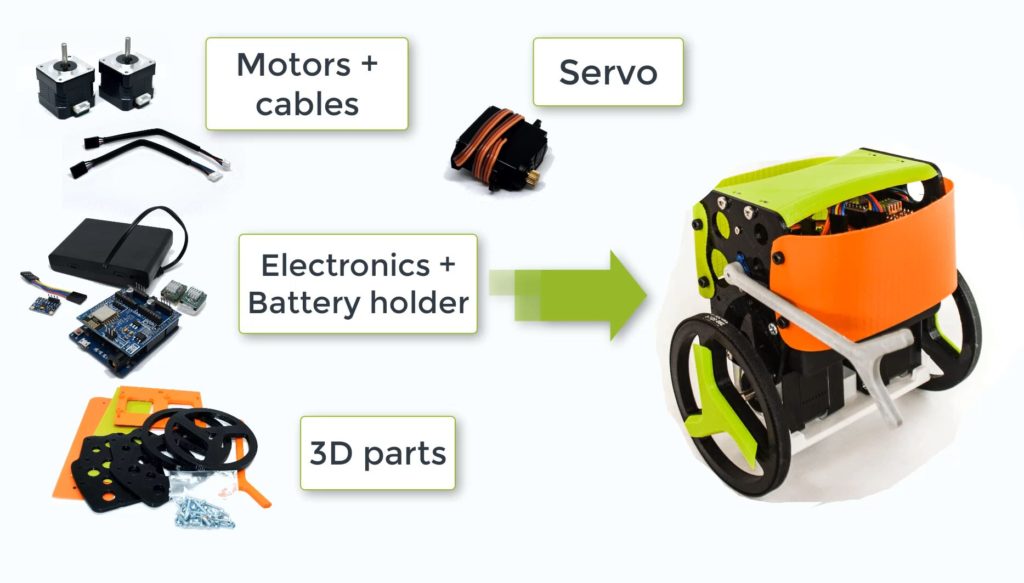
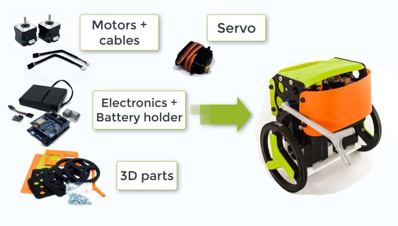
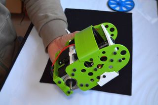
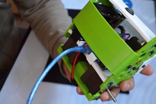
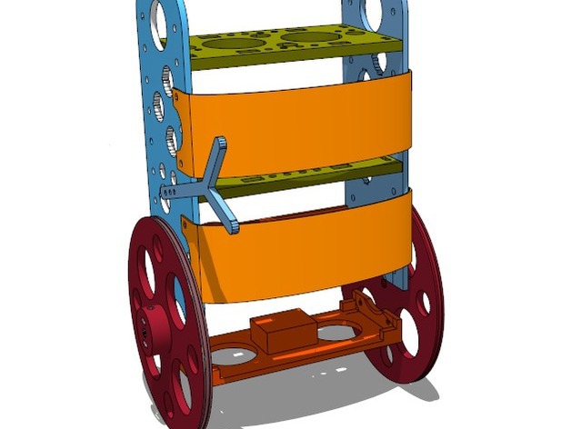
This COMPLETE VERSION includes all the electronic and hardware components required to create the B-Robot. You just need to assemble everything  (optional 3D parts)

What you get when you buy this KIT:

  •  jjRobots Brain Shield 
  •  Arduino Leonardo (CLONE) + USB cable (already programmed)
  •  2x High Quality NEMA17 stepper motors +14 cms cables (pair)
  •  2x Stepper motor driver
  •  IMU (gyro+accelerometers) + custom cable
  • Powerful servo: Metal gears (you will need an arm to fight and raise your B-robot…)
  • 6x AA Battery case with ON/OFF Switch  (batteries not included)
  • Bolts+nuts needed to set everything up
  • Pair of nylon bumpers (14×5 cms)
  • Double side tape, googly eyes…
  • Optional: 3D printed parts

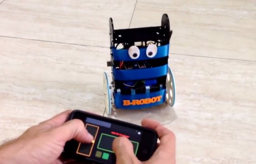
NEW: control your B-robot using the JJrobots FREE APP! (Android devices) or the Roverbot APP (for iOS phones. not official)

new B-ROBOT Evo 2 FEATURES:

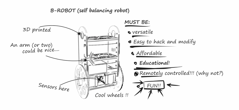
    • STEM education robot: perfect introduction to a robot that solves the inverted pendulum problem. Modify the B-robot EVO 2 as much as you can (both the robot parts themselves or its code) while you have fun!
    • Control it using your smartphone/tablet via the free jjRobots APP
    • Google Blockly controllable!
    • Perfect to have fun as you learn robotics (Take a look to the Robotics Challenges!)
    • Now can use regular AA batteries (or a 3 cells LIPO battery)
    • Two SERVO outputs (one used for the ARM). Both can be controlled from the jjRobots APP
    • Easier to print and using less plastic
    • PRO MODE can be activated from your smartphone/Tablet (increased agility and velocity)
    • Increased WIFI range (up to 40 meters)
    • Battery status
    • “Tilt angle” displayed in real time on your smartphone screen


logo GOOGLE PLAY v2


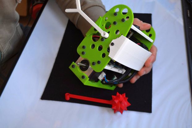
Personalise your B-robot to fight, create your own weapons, increase the size of the wheels… it is up to you! Take a look to some parts (and send us yours!)
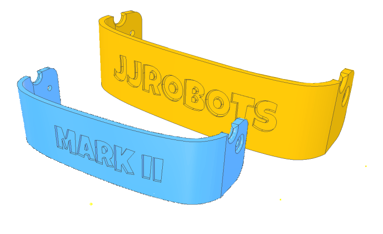
Customise your own bumper using the online tool at Thingiverse 


B-ROBOT Evo 2 Features:

  • STEM education robot.  In addition to being fun, the B-robot EVO 2 engage beginners and advanced students and incorporate many of the fundamental STEM concepts providing a learning platform that everyone enjoys
  • Control it using your smartphone/tablet using the free jjRobots APP
  • Google Blockly controllable
  • Perfect have fun as you learn about robotics (Take a look to the Robotics Challenges!)
  • Open Robot project: code and 3D design files are open and shared. You could personalise your robot as much as you want.
  • DIY & Hackeable: BROBOT is not a closed final product, BROBOT is an open, modifiable and hackeable platform, perfect to learn and play as much as you want!
  • Develop your own apps: You could modify the source code of BROBOT to perform new tasks but the communication protocol is also open so you can develop your own IOS, Android, PC remote apps to control your BROBOT!
  • Learn: BROBOT is a JJROBOTS product and this mean that you will receive a well documented project (source code and external documentation). We want you know all that is happening inside your Robot! This is ideal for learning and teaching technology. We will provide very good documentation. How we are controlling the motors, how we read and integrate the information from gyros and accelerometers, how we are controlling de stability of the robot, how we communicate with the control apps, etc…

– Build with your kids, at school, for yourself… this is a unique gadget. A perfect STEM education robot

– This self balancing robot has a medium size, perfect to carry your own beer (or mineral water ;-))

– There is a community behind BROBOT so you will have a forum to ask questions, share your experiences, MODs/ Hacks and contact other users…

– You can use these self balancing robot parts to create more robots or gadgets, keep in mind all the devices used in a BROBOT are standard electronic devices with a lot of potential. In the JJROBOTS community we want to show you how! You are now buying a self balancing robot, you are buying your a versatile set of electronics and ancillary devices.


B-Robot EVO 2. Much more than a self balancing robot


REMOTELY CONTROL YOUR B-ROBOT EVO


Control and tune-up your B-robot from your own smartphone/ tablet using the Control APP (freely available on Google play).

Modify its PID robotic control in real time and see how that affects to its behaviour and performance.

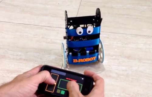
The new version displays the battery status and robot´s tilt angle in real time. Control the two servo output just tapping on the screen.


HAVE FUN LEARNING ROBOTICS

Learn Robotics and have fun with the STEM Challenges!

How does this robot work? Can I adjust its behaviour? And modify it?

STEM education robot:  In addition to being fun, the B-robot EVO 2 engage beginners and advanced students and incorporate many of the fundamental STEM concepts providing a learning platform that everyone enjoys

Bring a beverage can to the other side of the room not dropping it, race against other B-robots with different configurations and add-ons and understand what it is going on. The B-robot EVO 2 is a very versatile and fun STEM learning robot

CUSTOMISE YOUR ROBOT!

Create your own bumpers and personalise your B-robot with the online customisation tool on Thingiverse


USEFUL LINKS

B-Robot EVO 2 Assembly guide

Better than a bunch of photos we have created an Assembly guide video. Some steps, like how to program the Arduino, controlling your robot or Troubleshooting are listed below. The interactive 3D model will help you to get a good idea about how the B-robot EVO looks.

Part list:
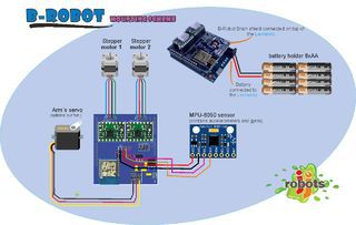
  •  jjRobots Brain Shield  (or equivalent: schematic info here)
  •  Arduino Leonardo (CLONE) + USB cable (already programmed)
  •  2x High Quality NEMA17 stepper motors +14 cms cables (pair)
  •  2x Stepper motor driver
  •  IMU (gyro+accelerometers) + custom cable
  • Optional: 3D printed parts (vibrant colours)
  • Powerful servo: Metal gears (you will need an arm to fight and raise your B-robot…)
  • 6x AA Battery case with ON/OFF Switch  (batteries not included)
  • Bolts+nuts needed to set everything up
  • Pair of nylon bumpers (14×5 cms)
  • Double side tape, googly eyes…

Have questions/ comments? Refer to the B-robot EVO community!

HOW TO:

UPLOAD the ARDUINO CODE to the ARDUINO LEONARDO

(skip this step if you got the Plug & Play B-robot EVO kit version. The Arduino is already programmed)

a) Install the Arduino IDE on your PC from (skip this step if you have the Arduino IDE already installed)
This B-robot code has been tested and developed on IDE version 1.6.5 and later versions. If you have a problem compiling the code, let us know
b) Download all the arduino files from GITHUB (https://github.com/jjrobots/B-ROBOT_EVO2/tree/master/Arduino/BROBOT_EVO2) or from here
Copy the files inside the BROBOT_EVO2 folder in your hard drive
c) Compile and send the code to the Arduino Leonardo
  1. Open your Arduino IDE
  2. Open the main code in /BROBOT_EVO2/BROBOT_EVO2-XX.ino
  3. Connect your Leonardo board with the USB to the PC
  4. Note: If this is the first time you connect a Leonardo board to your PC maybe you might need to install the driver.
  5. Select the board Leonardo (tools->board)
  6. Select the serial port that appears on the tools->Serial port
Send the code to the board (UPLOAD button: Arrow pointing to the RIGHT)
upload
d) Done!

CONTROL YOUR B-ROBOT EVO 2:

Android users:

We have developed a FREE APP to control the Brobot (and future JJrobots) for your Android based Smartphone/Tablet:

logo GOOGLE PLAY v2
Download it for FREE

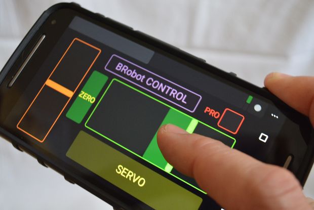
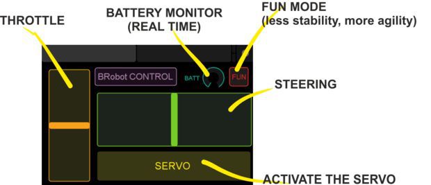
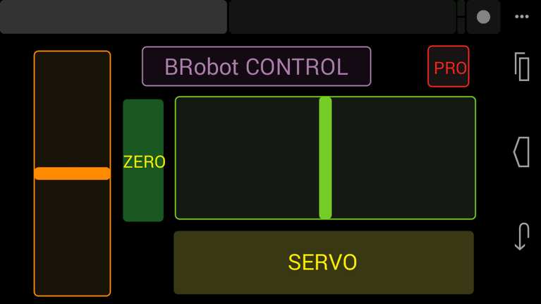
It works sending UDP packets to the B-robot. It uses a simple layout with Throttle and Steering slicers and several buttons.

Steps to follow:

  1. Install the JJRobots control APP
  2. After turning the Brobot EVO ON, connect your smartphone/tablet to the B-robot EVO´s wifi network (remember, the WIFI´s password is 87654321)
  3. Launch the JJrobots control APP and play with your B-robot EVO!

Above: Screen capture of the JJrobots B-robot control APP (available for free in GOOGLE PLAY)

iOS users. App Store App or TouchOSC :

iOS  B-robot control APP (thanks to Xuyen for this great contribution!)ios tiny2

It is quite straightforward to use. Just connect your iPhone/iPad to the B-robot EVO´s wifi (use the password “87654321“) and launch the App.

(thanks to Xuyen for this great contribution!)

iOS TouchOSC APP: Alternative way to control the B-robot EVO. Setup guide and files here 

USEFUL LINKS:

Arduino CODE (latest version V.2.0) and the GITHUB REPOSITORY

3D PARTS (STL) Files

B-robot Challenges (robotics, Academy)

B-robot alternative frames: Stealth versionCompact version (credits to s199)

B-robot EVO 2: 3D MODEL

TROUBLESHOOTING:

My B-robot is not responding to the command sent from my smartphone/tablet

Check you are connected to the JJROBOTS_XX netwrok using the correct password (by default: 87654321) and your device has not blocked the data traffic to the B-robot (stay always connected to the robot)

The IMU gets loose/ the i2C cable is too short

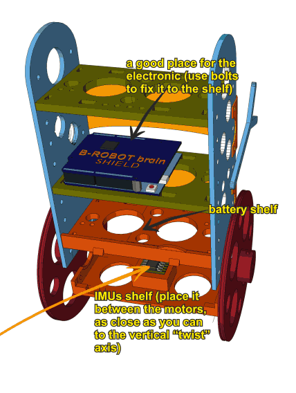
The gyroscope (IMU) is one of the most important element in this robot. It provides the current angle of the robot updating its value hundred times per second. The protocol used to send the data is quite sensitive to any electromagnetic interference so a very short cable is needed to connect the IMU and the Brain Shield. At the same time, vibrations create false angle measurements so we have to isolate the Brobot´s main frame vibrations from the IMU: that is the reason to use a double sided sticky pad to fix the IMU to the Brain Shield.

Place the IMU as indicated above: Close to the Brain Shield´s i2C connector. Bend the cable if needed. If you place the IMU as above, there should not be any lateral force pushing the IMU out of place

My B-robot lacks of power or fall without reason

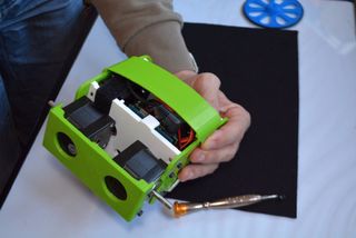
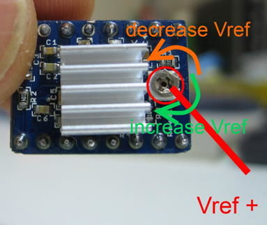
Adjust the current delivered by the stepper motors drivers. Use a screwdriver and gently rotate the screws indicated on the photo below. Rotating 10º-30º is more than enough.

Clockwise rotation: increase the power delivered to the motors


A4988 STEPPER MOTOR DRIVERS output current potentiometer

My B-robot can not stand up by itself.

If everything is ok, the B-robot only needs a little bit of help from the servo to stand up by itself. Take a look to the video below. If your robot does not behave like in the video, adjust the stepper motor drivers output power (instructions above). Keep in mind that the bumpers have two functions here: protect the electronics+robot and help it to stand up easily.

Video Player

DEBUG MODE

There is a DEBUG MODE inside the B-robot CODE. This MODE will allow you the debug the behaviour of the robot if you are having issues.  Please, refer to the B-robot community if you have problems or questions.

Look at the sketch line “#define DEBUG 0″ and change the 0 to 1…8 depending on what info you want to get. Take a look to the CODE below:

#if DEBUG==8
Serial.print(throttle);
Serial.print(” “);
Serial.print(steering);
Serial.print(” “);
Serial.println(mode);
#endif

//angle_adjusted_radians = angle_adjusted*GRAD2RAD;

#if DEBUG==1
Serial.println(angle_adjusted);

#endif

//Serial.print(“\t”);
mpu.resetFIFO(); // We always reset FIFO

// We calculate the estimated robot speed:
// Estimated_Speed = angular_velocity_of_stepper_motors(combined) – angular_velocity_of_robot(angle measured by IMU)
actual_robot_speed_Old = actual_robot_speed;
actual_robot_speed = (speed_M1 + speed_M2)/2; // Positive: forward

int16_t angular_velocity = (angle_adjusted-angle_adjusted_Old)*90.0; // 90 is an empirical extracted factor to adjust for real units
int16_t estimated_speed = -actual_robot_speed_Old – angular_velocity; // We use robot_speed(t-1) or (t-2) to compensate the delay
estimated_speed_filtered = estimated_speed_filtered*0.95 + (float)estimated_speed*0.05;

#if DEBUG==2
Serial.print(” “);
Serial.println(estimated_speed_filtered);
#endif

// SPEED CONTROL: This is a PI controller.
// input:user throttle, variable: estimated robot speed, output: target robot angle to get the desired speed
//target_angle = (target_angle + speedPControl(estimated_speed_filtered,throttle,Kp_thr))/2.0; // Some filtering : Average with previous output
//target_angle = target_angle*0.3 + speedPIControl(dt,estimated_speed_filtered,throttle,Kp_thr,Ki_thr)*0.7; // Some filtering
target_angle = speedPIControl(dt,estimated_speed_filtered,throttle,Kp_thr,Ki_thr);
target_angle = constrain(target_angle,-max_target_angle,max_target_angle); // limited output

#if DEBUG==3
Serial.print(” “);
Serial.println(estimated_speed_filtered);
Serial.print(” “);
Serial.println(target_angle);
#endif

#if DEBUG==10
Serial.print(angle_adjusted);
Serial.print(” “);
Serial.println(debugVariable);
#endif

#if DEBUG==6 //BATTERY STATUS
Serial.print(“B”);
Serial.println(battery);
Serial.print(” “);
#endif
#if DEBUG==7
Serial.print(distance_sensor);
Serial.print(” A”);
Serial.println(autonomous_mode_status);


USEFUL INFO: ARDUINO LEONARDO, IMU 6050 & STEPPER MOTOR DRIVER(A4988):

Arduino Leonardo:

  • Schematic can be found here
  • Info about this Arduino model here

MPU-6050 (gyro+accelerometers)

  • MPU-6050 series info can be found here
  • How to integrate it with any Arduino, here
  • Schematic and connection info, here

Stepper motor driver A4988:


FAQ (frequently asked questions):

Why are you using Stepper motors?

There are several options for motors: DC, Brushless, Steppers… We choose stepper motors because they have enough torque, you could connect the wheels directly without gears that generate some backslash (this is a common problem in balancing robots), they have good bearings and you will be able to control the speed of the motors with accuracy. In standard sizes these motors are cheap (we use the same motors used on a regular 3D printers) and the drivers are cheap and easy to interface with Arduino too.

Why you use a Wifi connection?

Using a Wifi connection allow us to work with a lot of devices (Smartphones, Tablets, PCs…) Bluetooth devices are cheaper but their range is usually shorter. Old devices are not supported and you could not connect it to Internet easily. The Wifi module that we recommend, allow us to create an Access Point, so you don’t need to use an existing Wifi infrastructure (cheap Wifi modules don´t let you do this). You can connect your device directly to the Robot anywhere but if you prefer you can hack it and use your own infrastructure therefore controlling your robot (or whatever you have created) over the Internet from any remote place in the world! (Cool, isn´t it?)

Why BROBOT?

Self balancing robots are fun to see and play. A self balancing robot requires sensors and control algorithms. You will find all the HOWTO and technical documents which explains the “behind the scenes” in JJROBOTS. Learn electronics and robotics creating your own BROBOT from scratch!.

There are some commercial solutions to the balancing robot, but here we want to share knowledge and thoughts. You can use the BROBOT parts to create more robots or gadgets, keep in mind all the devices used in a BROBOT are standard devices/electronics with a lot of potential. In the JJROBOTS community we want to show you how! You are now buying a self balancing robot, your are buying your own electronic and ancillary devices!

Thinking about creating a GPS self guidance robot? a modified version of BROBOT is your robot!

How much payload could carry BROBOT?

BROBOT could easily carry your soft-drink cans. We have tested with 500g of payload with success. More weight makes the robot more unstable but this could be fun also, isn’t it?

Why use stepper motors for a balancing robot?

There are several options for motors, DC, Brushless, Steppers… We choose stepper motors because they have enough torque, you could connect the wheels directly without gears that generate some backslash, they have good bearings and you could control the speed of the motors very precisely. Also they are cheap and the drivers too…

Could I use rechargeable batteries of Lipo batteries?

Yes, you could use standard AA batteries (alkaline recommended), AA rechargeable batteries (e.g. NiMh) or you could optionally use a 3S Lipo battery. Run Lipo batteries at your own responsibility.

What is the runtime of BROBOT?

With rechargeable AA batteries (e.g. Ni-Mh 2100mAh) you could expect around half to an hour of runtime

Could BROBOT work without the wifi module?

Yes, BROBOT could work and keep its stability. But, of course you could not control it without the module.


Could I change the name of the Wifi network that BROBOT generate?

Yes, on the configuration sketch you could change the name and also some other internet configurations. You could also connect BROBOT with your existing Wifi network

Is this a project for an Arduino beginner?

Well, BROBOT is not an easy “beginner project”, but it has a lot of documentation so you have a platform to grow your skills. You could first mount your BROBOT following the instructions and it should work OK, then you could start understanding some parts of the code and finally writing your own pieces of code…

For example it could be easily (there are tutorials for this) to write your code so the robot automatically move the arm and spin itself if you don’t send a command in 10 seconds…

More advanced hacks: Convert to a totally autonomous robot with obstacle avoiding adding a SONAR, convert to a follow line robot, and so on…

Why BROBOT electronics are not so cheap?

We are a really small startup (2 persons in our free time) and now we could only run small batch of electronics. As yo know the price of electronics drops quickly in high volume productions but we are starting… If we sell many boards and we could run more volume productions we will drop the prices!!. JJROBOTS didn´t born to get money, our spirit is to sell “good products” to found our next projects and spread the robotics knowledge

Have fun!

LINK: B-robot EVO original assembly guide 

Creating a Remotely Controlled Arduino Self Balancing Robot: B-robot EVO

How does it work?

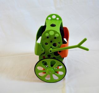
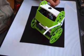
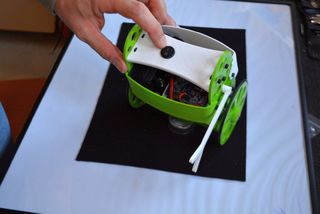
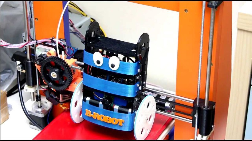
B-ROBOT EVO is a remotely controlled self balancing arduino robot created with 3D printed parts. With only two wheels, B-ROBOT is able to maintain its balance all the time by using his internal sensors and driving the motors. You can control your Robot, making him move or spin, by sending commands via a Smartphone, Tablet or PC while it maintains its balance.

This self balancing robot reads his inertial sensors (accelerometers and gyroscopes integrated on the MPU6000 chip) 200 times per second. He calculates his attitude (angle with respect to the horizon) and compares this angle with the target angle (0º if he wants to maintain balance without moving, or a positive or negative angle if he wants to move forward or backwards). Using the difference between the target angle (let’s say 0º) and actual angle (let’s say 3º) he drives a Control System to send the right commands to the motors to maintain his balance. The commands to the motors are accelerations. For example if the robot is tilted forward (angle of robot is 3º) then he sends a command to the motors to accelerate forward until this angle is reduced to zero to preserve the balance.

Step 1: A Bit More in Depth…

The physical problem that B-ROBOT solves is called the Inverted Pendulum. This is the same mechanism you need to balance an umbrella above your hand. The pivot point is under the center of mass of the object. More information on Inverted Pendulum here. The mathematical solution to the problem is not easy but we don’t need to understand it in order to solve our robot´s balance issue. What we need to know is how should do to restore the robot´s balance so we can implement a Control Algorithm to resolve the problem.

Control System is very useful in Robotics (an Industrial automation). Basically it´s a code that receives information from sensors and target commands as inputs and creates, in consequence, output signals to drive the Robot actuators (the motors in our example) in order to regulate the system. We are using a PID controller (Proportional + Derivative + Integral). This type of control has 3 constants to adjust kP,kD,kI. From Wikipedia: “A PID controller calculates an ‘error’ value as the difference between a measured [Input] and a desired setpoint. The controller attempts to minimize the error by adjusting [an Output].” So, you tell the PID what to measure (the “Input”),where you want that measurement to be (the “Setpoint”,) and the variable you wish to adjust to make that happen (the “Output”.)

The PID then adjusts the output trying to make the input equal the setpoint. For reference, a water tank we want to fill up to a level, the Input, Setpoint, and Output would be the level according to the water level sensor, the desired water level and the water pumped into the tank. kP is the Proportional part and is the main part of the control, this part is proportional to the error. kD is the Derivative part and is applied to the derivative of the error. This part depends on the dynamics of the system (depends on the robot,´s weight motors, inertias…). The last one, kI is applied to the integral of the error and is used to reduce steady errors, it is like a trim on the final output (think in the trim buttons on an RC car steering wheel to make the car go totally straight, kI removes the offset between the target required and the actual value).

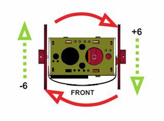
On B-ROBOT the steering command from the user is added to the motors output (one motor with a positive sign and the other with a negative sign). For example if the user sends the steering command 6 to turn to the right (from -10 to 10) we need to add 6 to the left motor value and subtract 6 from the right motor. If the robot is not moving forward or backwards, the result of the steering command is a spin of the robot

Step 2: What About the Remote Control?

We wanted B-ROBOT to be controlled by the user from almost any existing device, but we don´t want to develop a lot of different interfaces for different systems (Android, IOS, PC-windows…). Moreover, we decided to use existing (and powerful) protocols to control “things” and we found (some years ago) a protocol called OSC(Open Sound Control, more info here) used to control musical instruments like synthesizers. Very visual and powerful (we can display volume control, equalizers, lights…and create our own). To remotely control B-robot, we use OSC protocol over an Internet connection (Wifi module) using UDP packets. This is a lightweight and efficient way to send commands to our Robots!. We could also personalize the Interface we are using in our device so we will be able to control anything! (well…almost) What we need to do is to implement a lightweight library for Arduino in order to support this protocol (easy). We only use a subset of the OSC protocol to keep things small.

More info in the jjrobots webpage

Step 3: FIRST! Check You Have Everything You Need

  1. B-ROBOT electronic brain shield (or create your own PCB board using the info available here)
  2. B-Robot 3D printed plastic parts (STL models available here)
  3. Arduino LEONARDO
  4. 2x Stepper motor DRIVER (A4988)
  5. IMU MPU-6050 (gyro+accelerometer)
  6. 2x NEMA 17 stepper motors (40mm length, example:42BYGHW609)
  7. 8xAA battery holder (for NiMh or alkaline batteries)
  8. OPTIONAL: Mini servo (21g) to move the arm (this is a fun feature)

The easy way to get everything is buying from us (and that encourages us to keep doing these robots) here (plus bolts, nuts, strap…)

HINT:

We are working on other robots that are using the same electronics and ancillary elements. If you get the items above you will be capable of assemble new different robots soon. Take a look to them at the last step

Step 4: ​Programming the ARDUINO LEONARDO

a) Install the Arduino IDE on your PC from (skip this step if you have arduino already installed)

This B-robot code has been tested and developed on IDE version 1.6.5

b) Install the libraries (https://github.com/jjrobots/B-ROBOT/tree/master/libraries) Copy the folders inside the /libraries into the Arduino/libraries folder on your hard drive

JJROBOTS_BROBOT

JJROBOTS_OSC

I2Cdev

MPU6050

c)  Get the main CODE (https://github.com/jjrobots/B-ROBOT/tree/master/BROBOT).

d) Compile and send the code to the Arduino Leonardo:

  1. Open your Arduino IDE
  2. Open the main code in /BROBOT/BROBOT.ino
  3. Connect your Leonardo board with the USB to the PC
  4. Note: If this is the first time you connect a Leonardo board to your PC maybe you will need to install the driver.
  5. Select the board Leonardo (tools->board)
  6. Select the serial port that appears on the tools->Serial port
  7. Send the code to the board

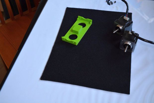
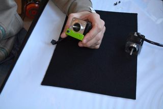
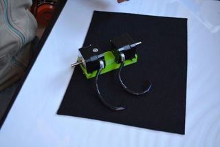
Step 5: Assemble the B-robot Frame+ Ancillary Elements

Step 6: (Optional But Recommended) Controlling the B-robot Using WIFI

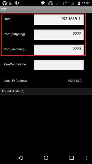
Setting up the TouchOSC software: If you are going to use the Touch OSC software to control the B-robot (and according to the current B-robot´s CODE available for the Arduino Leonardo), you will need to set these parameters in the TouchOSC like is shown in the images above.

Download the B-robot control layout (you can modify it if you want to) and install it using the OSCtouch APP

LINK: OSC layout used to control B-robot

Once the B.robot is switched on, a new WIFI signal will appear: “JJROBOTS-XX”. You will need to connect the controlling device to this network using the default WIFI password: 87654321

An OSC control software alternative: OSCillation and how to use it (Thanks Patrick!)

Step 7: ​Powering Up the B-robot:

  1. Lay down the B-robot on a static horizontal position in order to let it calibrate itself after powering it up.
  2. Turn the B-robot ON
  3. Let the B-robot 10 seconds to calibrate itself. Once self-calibrated, B-robot will spin its wheels a little.
  4. Time to stand up!: Use its arm or help it to stand up.

HINT: If the stepper motors do not have enough power to spin the wheels, try to adjust the current output in the A4988 stepper motor drivers rotating the screw indicated in the photo

QUESTIONS?

have a look to the B-robot forum

Step 8:

Other robots created (or under the last stage of development) which use the same electronics and ancillary elements.

THE B-ROBOT EVO (the self balancing robot)

 How does it work?

B-ROBOT is a remotely controlled self balancing arduino robot created with 3D printed parts. With only two wheels, B-ROBOT is able to maintain its balance all the time by using his internal sensors and driving the motors. You can control your Robot, making him move or spin,  by sending commands via a Smartphone, Tablet or PC while it maintains its balance.

Above: the B-Robot “brainstorming” creation ideas

This self balancing robot reads his inertial sensors (accelerometers and gyroscopes integrated on the MPU6000 chip) 200 times per second. He calculates his attitude (angle with respect to the horizon) and compares this angle with the target angle (0º if he wants to maintain balance without moving, or a positive or negative angle if he wants to move forward or backwards). Using the difference between the target angle (let’s say 0º) and actual angle (let’s say 3º) he drives a Control System to send the right commands to the motors to maintain his balance. The commands to the motors are accelerations. For example if the robot is tilted forward (angle of robot is 3º)then he sends a command to the motors to accelerate forward until this angle is reduced to zero to preserve the balance.

image02

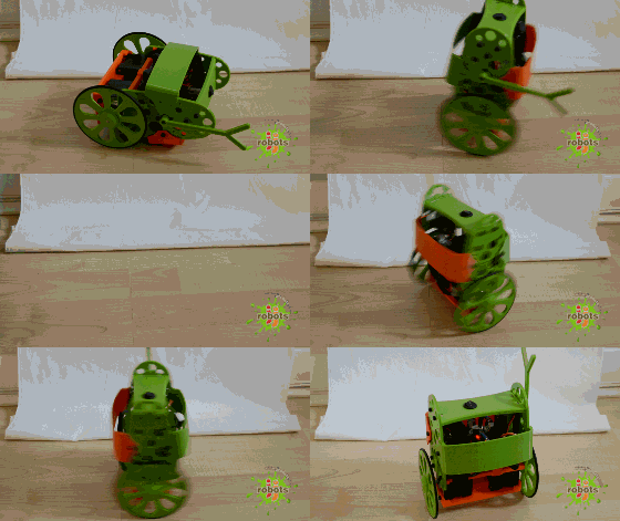
Stable position                  leaning forward                    Correcting its tilt using motors

A bit more in depth…

The physical problem that B-ROBOT solves is called the Inverted Pendulum. This is the same mechanism you need to balance an umbrella above your hand. The pivot point is under the center of mass of the object. More information on Inverted Pendulum here. The mathematical solution to the problem is not easy but we don’t need to understand it in order to solve our robot´s balance issue. What we need to know is how should do to restore the robot´s balance so we can implement a Control Algorithm to resolve the problem.

Control System is very useful in Robotics (an Industrial automation). Basically it´s a code that receives information from sensors and target commands as inputs and creates, in consequence, output signals to drive the Robot actuators (the motors in our example) in order to regulate the system. We are using a PID controller (Proportional + Derivative + Integral). This type of control has 3 constants to adjust kP,kD,kI.

 From Wikipedia: “A PID controller calculates an ‘error’ value as the difference between a measured [Input] and a desired setpoint. The controller attempts to minimize the error by adjusting [an Output].”

 So, you tell the PID what to measure (the “Input”) ,where you want that measurement to be (the “Setpoint”,) and the variable you wish to adjust to make that happen (the “Output”.) The PID then adjusts the output trying to make the input equal the setpoint.

For reference, a water tank we want to fill up to a level, the Input, Setpoint, and Output would be the level according to the water level sensor, the desired water level and the water pumped into the tank.


kP is the Proportional part and is the main part of the control, this part is proportional to the error. kD is the Derivative part and is applied to the derivative of the error. This part depends on the dynamics of the system (depends on the robot,´s weight motors, inertias…). The last one, kI is applied to the integral of the error and is used to reduce steady errors, it is like a trim on the final output (think in the trim buttons on an RC car steering wheel to make the car go totally straight, kI removes the offset between the target required and the actual value).

More information on PID controller here.

On B-ROBOT the steering command from the user is added to the motors output (one motor with a positive sign and the other with a negative sign). For example if the user sends the steering command 6 to turn to the right (from -10 to 10) we need to add 6 to the left motor value and subtract 6 from the right motor. If the robot is not moving forward or backwards, the result of the steering command is a spin of the robot.

image01

Above: Top view of the B-ROBOT and the commands to the motors


What about the user control?

NEW: (Android devices) control your B-robot using the JJrobots FREE APP! 
logo GOOGLE PLAY v2

We have developed an APP for Android users that simplifies the control of the B-robot EVO.

NEW: adjust the stability and behaviour of the B-robot in real time from the PID control APP (free)

More info in the assembly guide page

NEW: (iOS devices)

B-robot control APP (thanks to Xuyen for this great contribution!)


We wanted B-ROBOT to be controlled by the user from almost any existing device, but we don´t want 😉 to develop a lot of  different interfaces for different systems (Android, IOS, PC-windows…). Moreover, we decided to use existing (and powerful) protocols to control “things” and we found (some years ago) a protocol called OSC (Open Sound Control, more info here) used to control musical instruments like synthesizers. Very visual and powerful (we can display  volume control, equalizers, lights…and create our own). To remotely control B-robot, we use OSC protocol over an Internet connection (Wifi module) using UDP packets. This is a lightweight and efficient way to send commands to our Robots!. We could also  personalize the Interface we are using in our device so we will be able to control anything! (well…almost) What we need to do is to implement a lightweight library for Arduino in order to support this protocol (easy). We only use a subset of the OSC protocol to keep things small.

image04 v2
OSC interface on an Android Device.
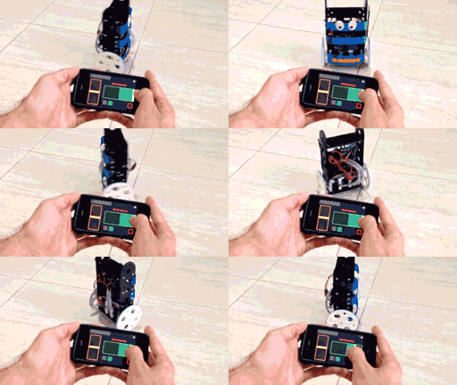
animacion-test-para-Brobot
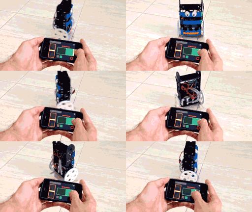
controlling the B-ROBOT (the old version in this case)


More about the Control System…

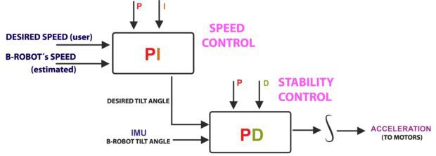
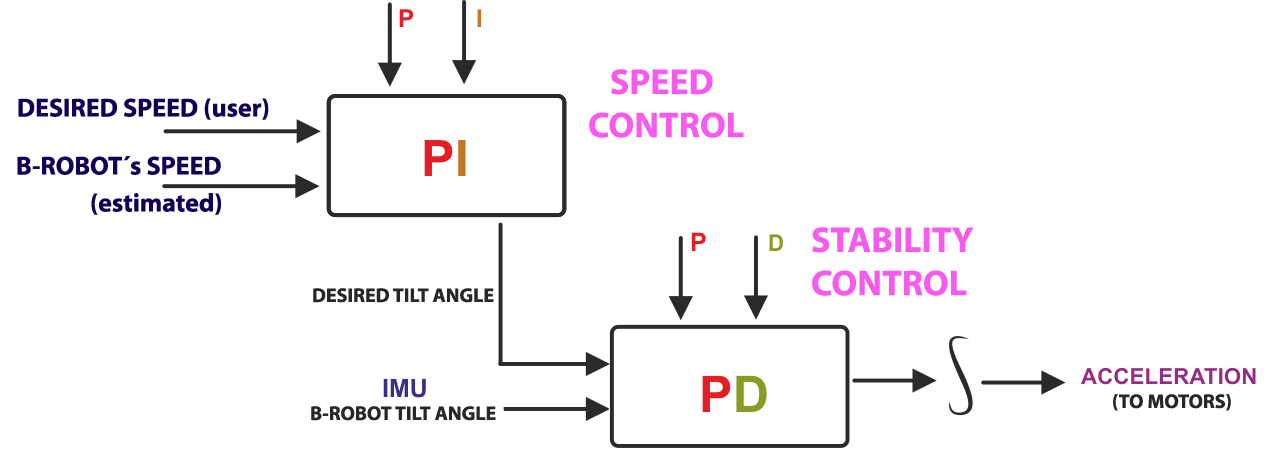
But things are a bit more complex… We have really two PID controllers in a cascade configuration (the output of one controller connected to the next one). The output controller is a speed controller and the inner controller is the stability controller.

BROBOT_control1

ABOVE: B-ROBOT  control algorithm loop


We could use only one stability controller (the second one) but this would mean that the control´s output would be the desired robot tilt angle, so the user would control the robot angle directly. The problem is that if the center of gravity is not perfectly located above the wheels axis , so the robot needs a little tilt angle to keep the balance and if the user sends a command of tilt=0 then the robot will maintain its balance whilst moving… When adding the second controller (speed controller) the system compensates automatically for this. The user sends a command to the robot speed=0 and this controller will send the “correct” tilt angle to the second controller (stability controller) to mantain the robot balanced and not moving! For the users it is much simpler to set the desired robot speed and the system will find the right robot angle to achieve this speed.


Now… How to create a self balancing robot like B-robot


To create a B-ROBOT, you will need:

  1. B-ROBOT electronic brain shield
  2. B-Robot 3D printed plastic parts (include bolts+nuts+ON/OFF switch) or print them by yourself (DOWNLOAD B-robot EVO STL 3D parts)
  3. Arduino LEONARDO 
  4. 2x Stepper motor DRIVER (A4988)
  5. IMU (gyro+accelerometer)
  6. 2x NEMA 17 stepper motors (40mm length, example:42BYGHW609)
  7. 8xAA battery holder (for NiMh or alkaline batteries)
  8. OPTIONAL: Mini servos (21g) to move the arm (arms)
  9. Programming the Leonardo with the latest code (ESP12-E version)
  10. Have a look to the FORUM, there you will find modifications of the robots (sonar sensors, different cases, sizes…)


FAQ: More questions


Why are you using Stepper motors?

There are several options for motors: DC, Brushless, Steppers… We choose stepper motors because they have enough torque, you could connect the wheels directly without gears that generate some backslash (this is a common problem in balancing robots), they have good bearings and you will be able to control the speed of the motors with accuracy. In standard sizes these motors are cheap (we use the same motors used on a regular 3D printers) and the drivers are cheap and easy to interface with Arduino too.

Why you use a Wifi connection?

Using a Wifi connection allow us to work with a lot of devices (Smartphones, Tablets, PCs…) Bluetooth devices are cheaper but their range is usually shorter. Old devices are not supported and you could not connect it to Internet easily. The Wifi module that we recommend, allow us to create an Access Point, so you don’t need to use an existing Wifi infrastructure (cheap Wifi modules don´t let you do this). You can connect your device directly to the Robot anywhere but if you prefer you can hack it and use your own infrastructure therefore controlling your robot (or whatever you have created) over the Internet from any remote place in the world! (Cool, isn´t it?)

Why BROBOT?

Self balancing robots are fun to see and play. A self balancing robot requires sensors and control algorithms. You will find all the HOWTO and technical documents which explains the “behind the scenes” in JJROBOTS. Learn electronics and robotics creating your own BROBOT from scratch!.

There are some commercial solutions to the balancing robot, but here we want to share knowledge and thoughts. You can use the BROBOT parts to create more robots or gadgets, keep in mind all the devices used in a BROBOT are standard devices/electronics with a lot of potential. In the JJROBOTS community we want to show you how! You are now buying a self balancing robot, your are buying your own electronic and ancillary devices!

Thinking about creating a GPS self guidance robot? a modified version of BROBOT is your robot!

How much payload could carry BROBOT?

BROBOT could easily carry your soft-drink cans. We have tested with 500g of payload with success. More weight makes the robot more unstable but this could be fun also, isn’t it?

Why use stepper motors for a balancing robot?

There are several options for motors, DC, Brushless, Steppers… We choose stepper motors because they have enough torque, you could connect the wheels directly without gears that generate some backslash, they have good bearings and you could control the speed of the motors very precisely. Also they are cheap and the drivers too…

Could I use rechargeable batteries of Lipo batteries?

Yes, you could use standard AA batteries (alkaline recommended), AA rechargeable batteries (e.g. NiMh) or you could optionally use a 3S Lipo battery. Run Lipo batteries at your own responsibility.

What is the runtime of BROBOT?

With rechargeable AA batteries (e.g. Ni-Mh 2100mAh) you could expect around half to an hour of runtime

Could BROBOT work without the wifi module?

Yes, BROBOT could work and keep its stability. But, of course you could not control it without the module.

Could I change the name of the Wifi network that BROBOT generate?

Yes, on the configuration sketch you could change the name and also some other internet configurations. You could also connect BROBOT with your existing Wifi network

Is this a project for an Arduino beginner?

Well, BROBOT is not an easy “beginner project”, but it has a lot of documentation so you have a platform to grow your skills. You could first mount your BROBOT following the instructions and it should work OK, then you could start understanding some parts of the code and finally writing your own pieces of code…

For example it could be easily (there are tutorials for this) to write your code so the robot automatically move the arm and spin itself if you don’t send a command in 10 seconds…

More advanced hacks: Convert to a totally autonomous robot with obstacle avoiding adding a SONAR, convert to a follow line robot, and so on…

Why BROBOT electronics are not so cheap?

We are a really small startup (2 persons in our free time) and now we could only run small batch of electronics. As yo know the price of electronics drops quickly in high volume productions but we are starting… If we sell many boards and we could run more volume productions we will drop the prices!!. JJROBOTS didn´t born to get money, our spirit is to sell “good products” to found our next projects and spread the robotics knowledge

If you want to know more, we recommend you have a look at the B-ROBOT´s code (or to the jjrobots forum).


jjrobotsJJROBOTS Science&fun 2015

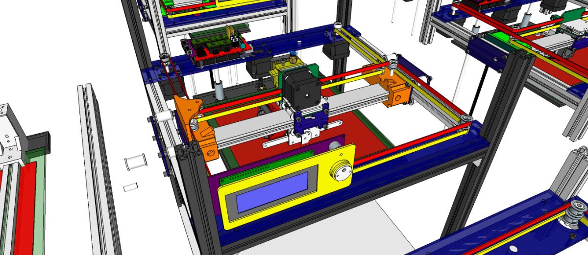
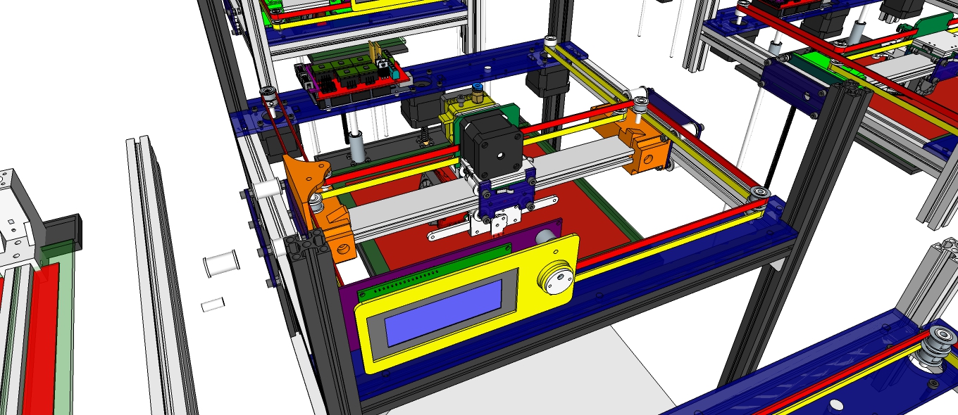
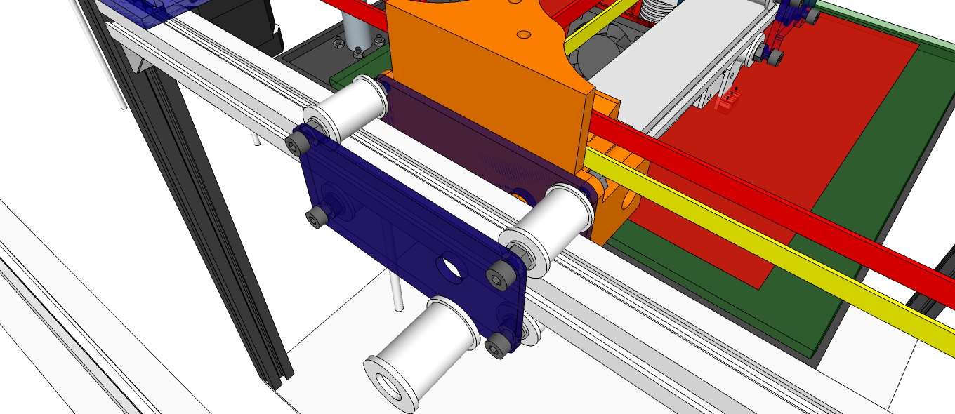
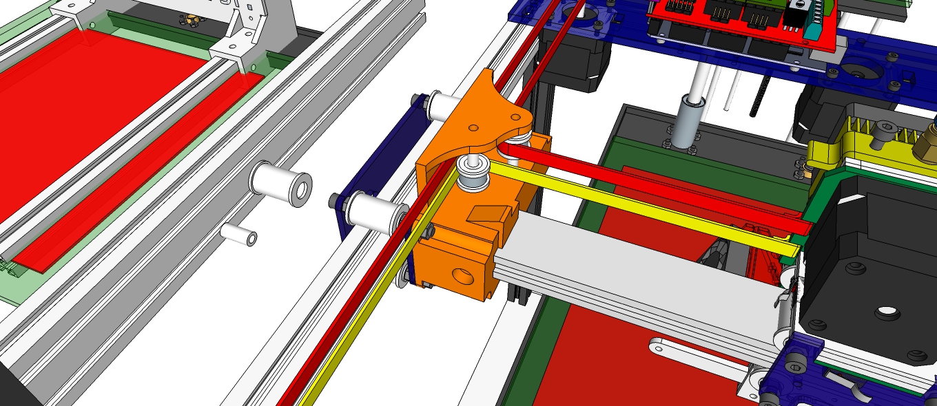
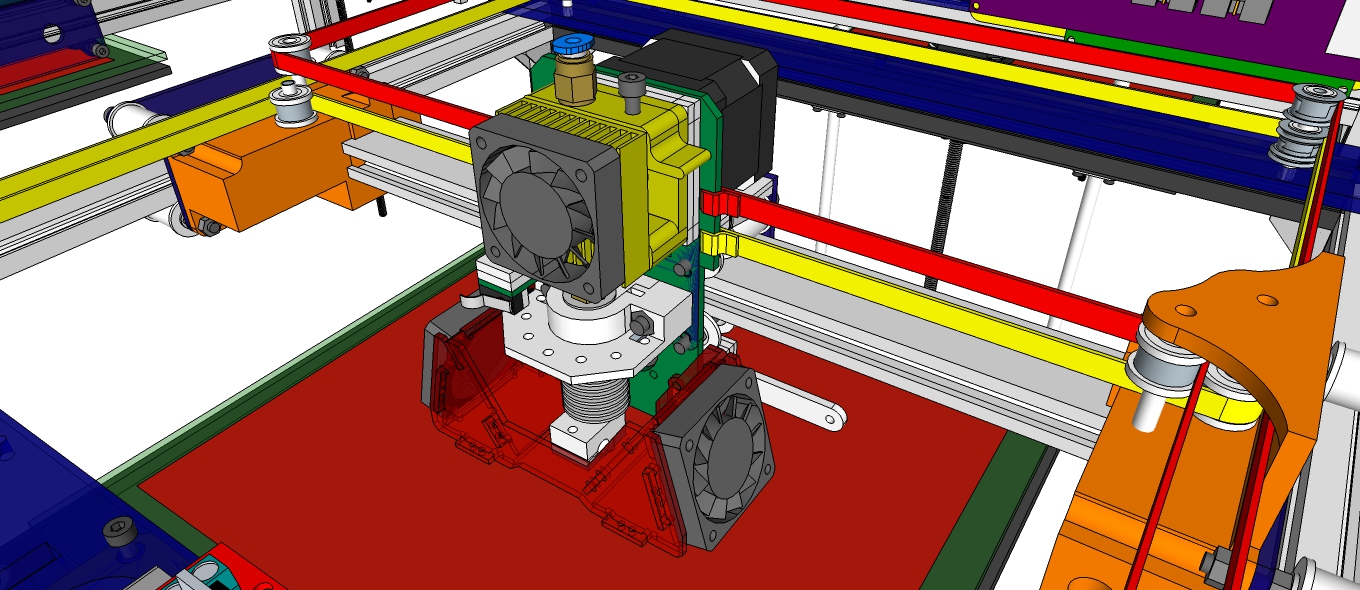
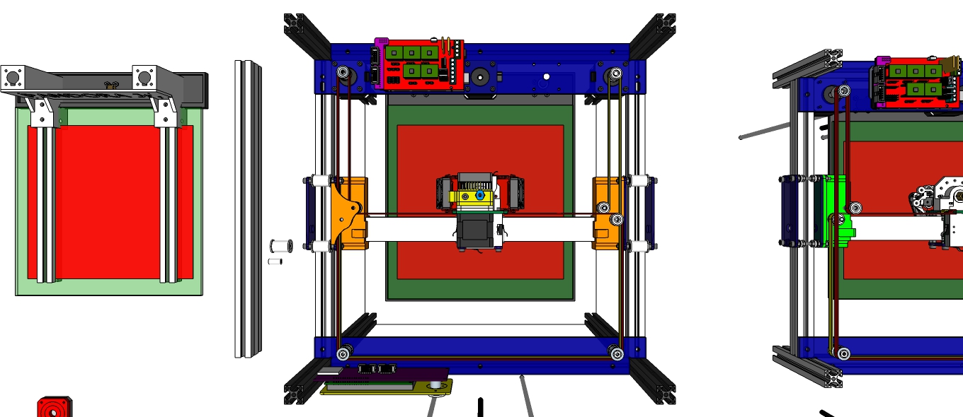
PANDORA Junior DXs – 3D Design Concept

DIY 3D Printer – PANDORA Junior DXs (Design eXtreme single)

3D Design Tool: SketchUp Pro

Technical Specifications

Printing

Technology: FFF(Fused Filament Fabrication) / CoreXY
Build Volume: 223 (W) x 207 (D) x 250 (H) mm – Heatbed
Layer Resolution: 50 ~ 200 microns
Filament: ABS or PLA, Nyron, HIPS, PVA… 1.75 mm diameter
Nozzle Diameter: 0.4 mm (0.2mm, 0.3mm, 0.8mm)
Print File Type: .Code, .STL
Layer Resolutions:

  • Fast: 200 micron (0.2 mm)
  • Normal: 100 micron (0.1 mm)
  • hHigh: 0.06 micron (0.06 mm)
  • Ultra High: 0,04 micron (0.04 mm)

Size and Weight

Product Dimensions: 410 (W) x 410 (D) x 485 (H) mm
Product Weight: 11 kg(?)

Software

Software Bundle: Cura, Slic3r, KISSlicer / Octoprint, Printrun, Repetier-Host, MatterControl
Supported File Types: .STL, .OBJ, .AMF, .Gcode
Operating Systems: All (Web-based): Windows, Mac OS, Linux

Firmware

Arduino: Modified Marlin v1.0.2-2
Raspberry Pi: Rasbian, Octoprint, SSH, Samba, VNC, WiringPi

Hardware

Base Plate: Profile DRF 2020, Acrylic
Step Motor: NEMA 17 – Phase: 4, Step Angle: 1.8 Deg/Step, Holding Torque: 2.6Kg.cm

  • X/Y/Z/E – 4EA
    Cartesian (xyz): X/Y Head: Profile DRF 2020, Z Bed: 10mm Linear Shaft and 8D Screw Rod

Electrical

Control Board: Arduino Mega 2560
Control Shield: Ramps 1.4 Board
Display Board: Reprap Discount Smart Controller LCD 2004
Raspberry Pi: Raspberry Pi 2/3
Camera: Raspberry Camera
Power Requirements: AC 100 – 240 V, 1.4 Amps, 50-60 Hz, 220 W
Connectivity: USB, SD Card, Wi-Fi (Web-based)
Temperature:

  • Nozzle temperature: 170 – 270
  • Heated bed temperature: 50 – 100
  • Operational temperature: 10 – 40
  • Storage temperature: 0 – 32

https://youtu.be/MC2KeKuKM1A


Thanks for watching!……..Coming soon!……..Updating……

Blog:
http://zddh.blogspot.kr/2017/12/pandora-junior-dxs-3d-design-concept.html

The open source PANDORA DXs hardware and software is free and made with love. Please show your level of support with a voluntary donation.

Donate:
https://www.paypal.com/cgi-bin/webscr?cmd=_s-xclick&hosted_button_id=RDN7ZGAVFS5UE

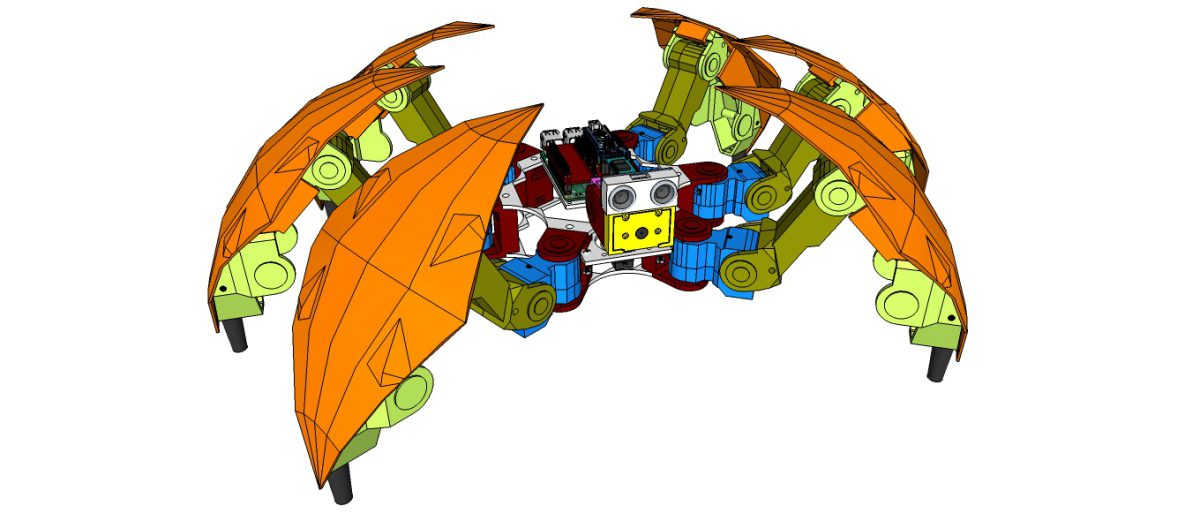
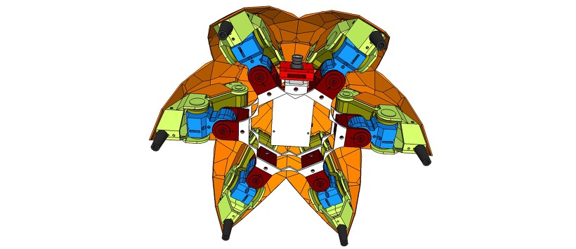
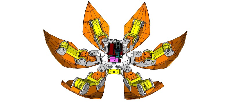
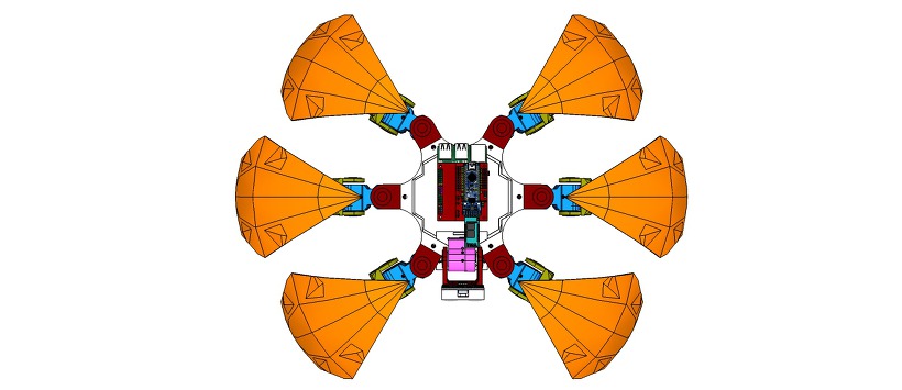
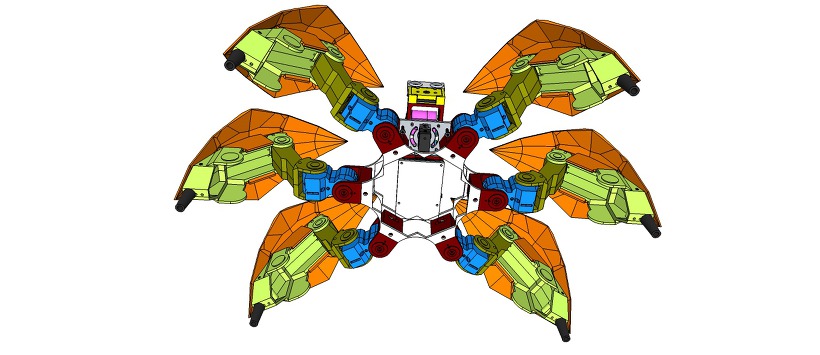
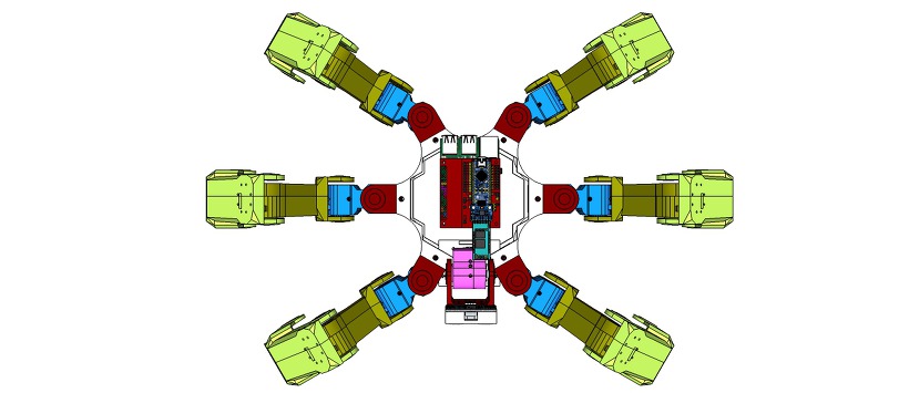
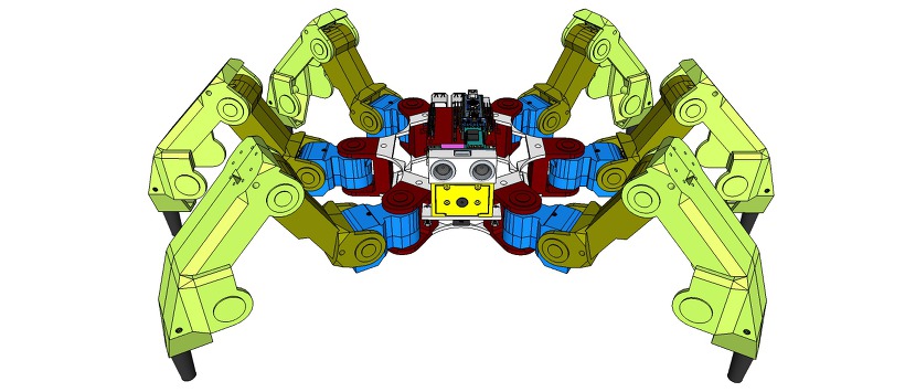
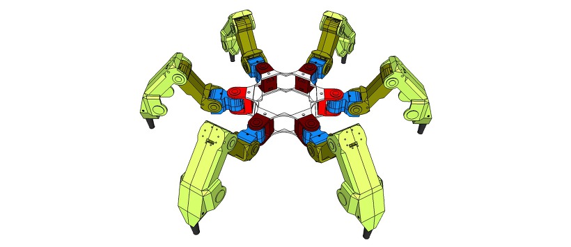
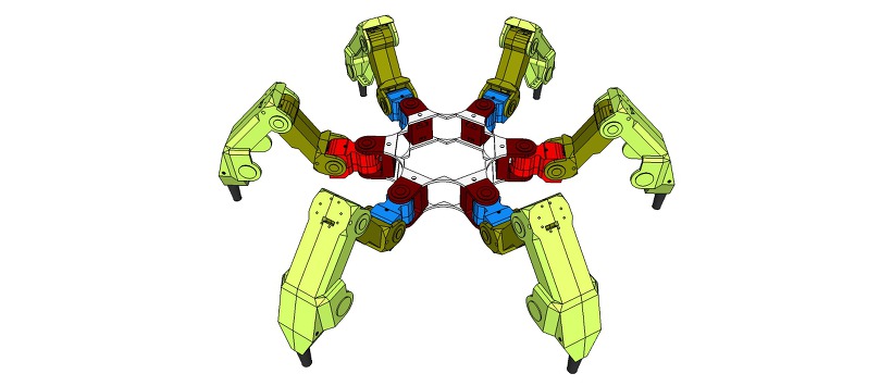
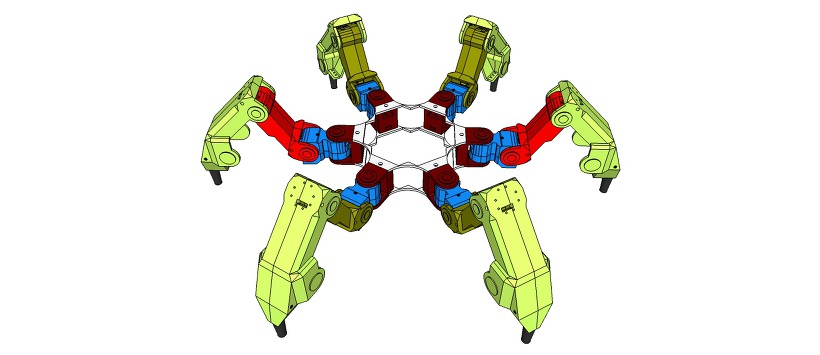
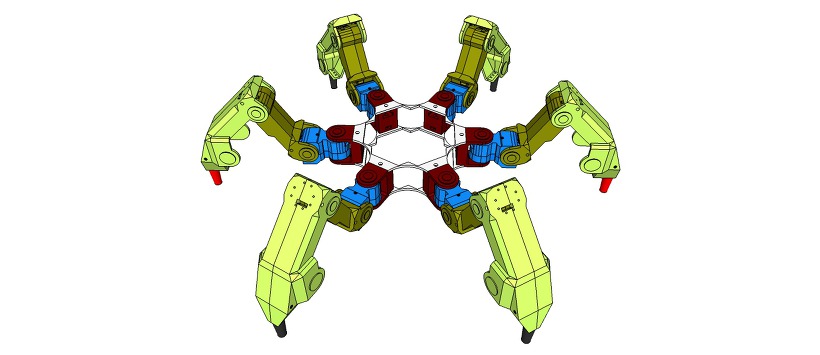
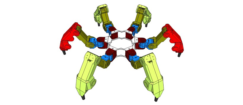
Project Hexapod Robot – H1 – Design concept

[ Update parts 20170418]

[ Upload design concept 20161001]


Project Hexapod Robot – H1 – Design concept


3D Design Tool: SketchUp Pro

https://youtu.be/_rR-UHH5oTU

Parts List

The open source Hexapod Robot – H1 software is free and made with love. Please show your level of support with a voluntary donation.

Donate:
https://www.paypal.com/cgi-bin/webscr?cmd=_s-xclick&hosted_button_id=RDN7ZGAVFS5UE

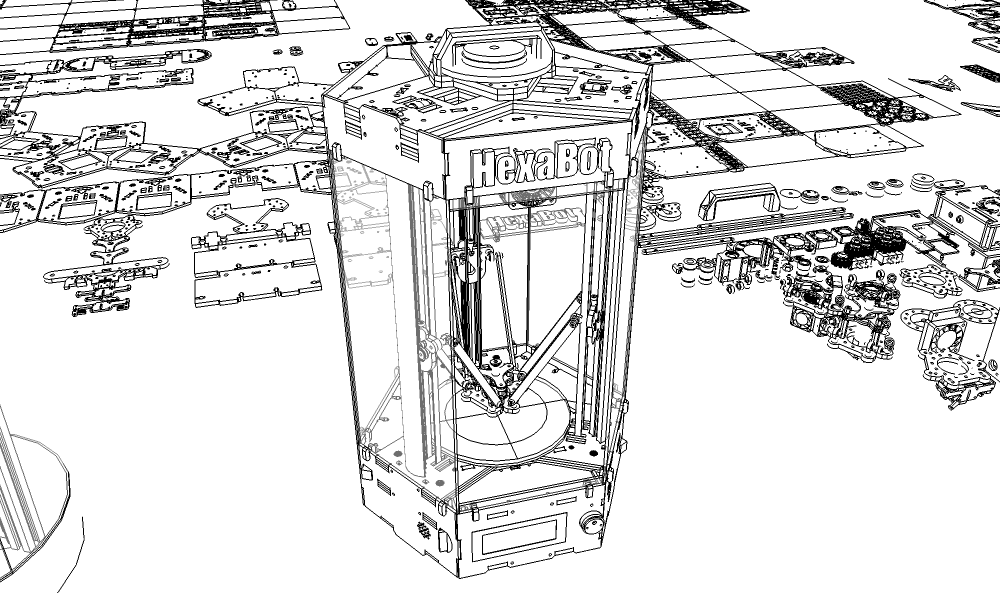
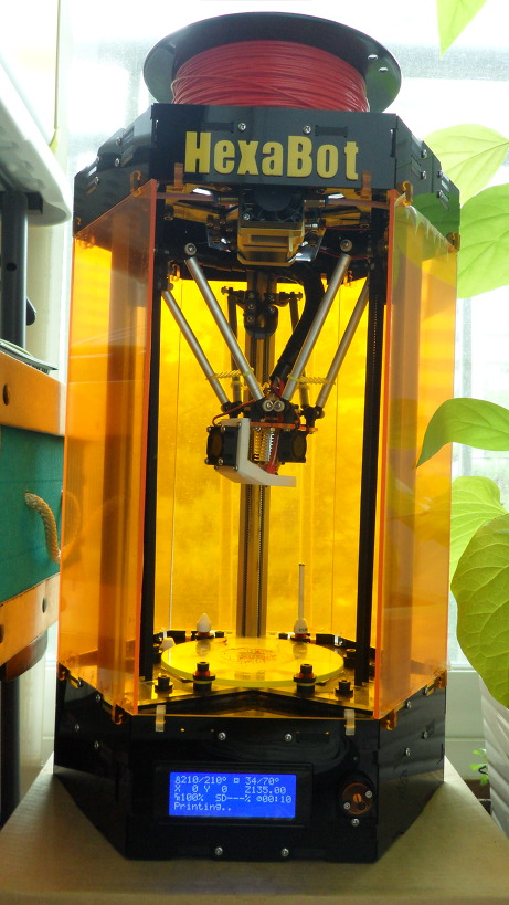
DIY Delta 3D Printer – HexaBot

DIY Delta 3D Printer – HexaBot
3D Design Tool: SketchUp Pro


Technical Specifications


Printing


Technology: FFF(Fused Filament Fabrication) / Delta
Build Volume: 95 (W) x 95 (D) x 135 (H) mm

  • Auto running Heatbed
    Layer Resolution: 50-200 microns
    Filament: ABS or PLA, Nyron, HIPS, PVA… 1.75 mm diameter
    Nozzle Diameter: 0.4 mm (0.2mm, 0.3mm, 0.8mm)
    Print File Type: .Gcode, .STL
    Layer Resolutions:
  • Fast: 200 micron (0.2 mm)
  • Normal: 100 micron (0.1 mm)
  • hHigh: 0.06 micron (0.06 mm)
  • Ultra High: 0,04 micron (0.04 mm)

    Size and Weight


    Product Dimensions: 260 (W) x 300 (D) x 460 (H) mm
    Product Weight: 4.5 kg


    Software

Software Bundle: Cura, Slic3r, KISSlicer / Octoprint, Printrun, Repetier-Host, MatterControl
Supported File Types: .STL, .OBJ, .AMF, .Gcode
Operating Systems: All (Web-based): Windows, Mac OS, Linux


Firmware


Arduino: Modified Marlin v1.0.0
Raspberry Pi: Rasbian, Octoprint, SSH, Samba, VNC, WiringPi


Hardware


Base Plate: Profile DRF 2020, Acrylic
Step Motor: NEMA 17 – Phase: 4, Step Angle: 1.8 Deg/Step, Holding Torque: 2.6Kg.cm

  • X/Y/Z/E – 4EA
    Cartesian (xyz): X/Y Head: LM Guide, Z Bed: 10mm Linear Shaft and 8D Screw Rod


    Electrical


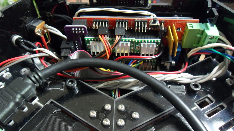
    Control Board: Arduino Mega 2560
    Control Shield: Ramps 1.4 Board
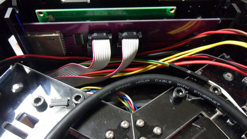
    Display Board: Reprap Discount Smart Controller LCD 2004
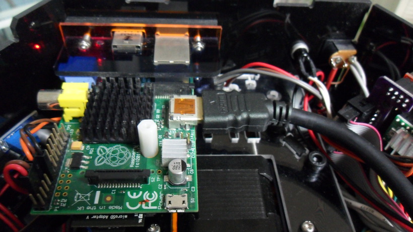
    Raspberry Pi: Raspberry Pi B
    Power Requirements: AC 100 – 240 V, 50-60 Hz, 12 VDC, 4.5A, 54 W
    Connectivity: USB, SD Card, Wi-Fi (Web-based)
    Temperature:

  • Nozzle temperature: 170 – 270
  • Heated bed temperature: 50 – 100
  • Operational temperature: 10 – 40
  • Storage temperature: 0 – 32

    https://www.thingiverse.com/thing:917729


    Thanks for watching!…….coming soon!……Updating……

The open source HexaBot hardware and software is free and made with love. Please show your level of support with a voluntary donation.

Donate:
https://www.paypal.com/cgi-bin/webscr?cmd=_s-xclick&hosted_button_id=RDN7ZGAVFS5UE