DIY 3D Printer PANDORA DXs

DIY 3D Printer – PANDORA DXs (Design eXtreme single)
3D Design Tool: SketchUp Pro


Technical Specifications


Printing


Technology: FFF(Fused Filament Fabrication) / H-Bot(CoreXY)
Build Volume: 223 (W) x 225 (D) x 165 (H) mm

  • Heatbed
    Layer Resolution: 50-200 microns
    Filament: ABS or PLA, Nyron, HIPS, PVA… 1.75 mm diameter
    Nozzle Diameter: 0.4 mm (0.2mm, 0.3mm, 0.8mm)
    Print File Type: .Gcode, .STL
    Layer Resolutions:
  • Fast: 200 micron (0.2 mm)
  • Normal: 100 micron (0.1 mm)
  • hHigh: 0.06 micron (0.06 mm)
  • Ultra High: 0,04 micron (0.04 mm)

    Size and Weight


    Product Dimensions: 426 (W) x 433 (D) x 500 (H) mm
    Product Weight: 11 kg


    Software


    Software Bundle: Cura, Slic3r, KISSlicer / Octoprint, Printrun, Repetier-Host, MatterControl
    Supported File Types: .STL, .OBJ, .AMF, .Gcode
    Operating Systems: All (Web-based): Windows, Mac OS, Linux


    Firmware


    Arduino: Modified Marlin v1.0.0
    Raspberry Pi: Rasbian, Octoprint, SSH, Samba, VNC, WiringPi


    Hardware


    Base Plate: Profile DRF 3030, Acrylic
    Step Motor: NEMA 17 – Phase: 4, Step Angle: 1.8 Deg/Step, Holding Torque: 2.6Kg.cm

  • X/Y/Z/E – 4EA
    Cartesian (xyz): X/Y Head: LM Guide, Z Bed: 10mm Linear Shaft and 8D Screw Rod


    Electrical


    Control Board: Arduino Mega 2560
    Control Shield: Ramps 1.4 Board
    Display Board: Reprap Discount Smart Controller LCD 2004
    Raspberry Pi: Raspberry Pi B
    Camera: Raspberry Camera
    Power Requirements: AC 100 – 240 V, 1.4 Amps, 50-60 Hz, 220 W
    Connectivity: USB, SD Card, Wi-Fi (Web-based)
    Temperature:

  • Nozzle temperature: 170 – 270
  • Heated bed temperature: 50 – 100
  • Operational temperature: 10 – 40
  • Storage temperature: 0 – 32

    https://www.thingiverse.com/thing:917718


    Thanks for watching!……..Coming soon!……..Updating……

The open source PANDORA DXs hardware and software is free and made with love. Please show your level of support with a voluntary donation.

Donate:
https://www.paypal.com/cgi-bin/webscr?cmd=_s-xclick&hosted_button_id=RDN7ZGAVFS5UE

FAN 90mm Replacement

3D Printer: PANDORA DXs – DIY Desktop 3D Printer


Slicer: Cura 14.12.1


Layer height (mm): 0.1
Shell thickness (mm): 0.8

Bottom/Top thickness (mm): 0.8
Fill Density (%): 0

Print speed (mm/s): 60
Print temperature: 190
Bed temperature: 60

Filament: PLA
Filament Diameter (mm): 1.75


3D Files:

https://www.thingiverse.com/thing:914300

Kitchen Sink Drain Cover

3D Printer: PANDORA DXs – DIY Desktop 3D Printer


3D Design Tool: SketchUp Pro


Slicer: Cura 14.12.1


Layer height (mm): 0.1
Shell thickness (mm): 0.8

Bottom/Top thickness (mm): 0.8
Fill Density (%): 0

Print speed (mm/s): 60
Print temperature: 190
Bed temperature: 60

Filament: PLA
Filament Diameter (mm): 1.75


Coating… After printing
Used 3mm tapping screw


3D Files:

https://www.thingiverse.com/thing:914094

MobBob V2 Remix Upgrade – Smart Phone Controlled Robot

[Update 20160212]
Add MobBob2_Remix_PowerBank_Hook.stl
Add MobBob2_Remix_Jacket.stl
Add MobBob2_Remix_Nano_Shield_Mount.stl

[Update 20160120]
Add Test #3 Video

[Update 20160119]
Add Test #1, #2 Video
Add MobBob2_Remix_Hand_Back_L.stl, MobBob2_Remix_Hand_Front_L.stl
Add MobBob2_Remix_Arm_Back_L.stl, MobBob2_Remix_Arm_Front_L.stl
Add MobBob2_Remix_Shoulder_L.stl
Add MobBob2_Remix_Hand_Back_R.stl, MobBob2_Remix_Hand_Front_R.stl
Add MobBob2_Remix_Arm_Back_R.stl, MobBob2_Remix_Arm_Front_R.stl
Add MobBob2_Remix_Shoulder_R.stl

[Update 20160105]
Printing errors corrected
MobBob2_Remix_Foot_L_Top.stl, MobBob2_Remix_Foot_R_Top.stl

[Upgrade 20160104]
Redesign Foot
MobBob2_Remix_Foot_L_Top.stl, MobBob2_Remix_Foot_L_Floor.stl
MobBob2_Remix_Foot_R_Top.stl, MobBob2_Remix_Foot_R_Floor.stl
Base Design: http://www.thingiverse.com/thing:1232619


Smart Phone Controlled Robot – MobBob V2 Remix Upgrade


3D Design Tool: SketchUp Pro
Design concept: RAPIRO – The Humanoid Robot and Gundam

This is an upgrade version of my MobBob V2 Remix robot.

MobBob is a smart phone controlled robot. By harnessing the power of your smart phone, MobBob is a walking, talking robot with voice recognition and computer vision that you can build for around $35. I will be continuing to extend his features over time. I want MobBob to be a companion robot that everyone can afford and have fun with.

You can see videos of MobBob V2 Remix upgrade in action here:
https://youtu.be/8nO0kziJvsk – 3D Design
https://youtu.be/ehrsIDJcVZY – Test #1
https://youtu.be/j0oz8OPYhNs – Test #2
https://youtu.be/5z4Ps11t-vE – Test #3
…..
Coming soon!!

The main aims of the V2 remix were to:

Support standard 9g servos [previously I was using Tower Pro SG90 servos]
Make everything easier to assemble [no more need for glue]
Make it easier to adapt/modify for other phones. The new bracket system made it easier to exchange a new phone / the battery holder.

Also, in my V2 Remix Upgrade build, I’m also using the Arduino Nano instead of the DIY Nano shield, so the entire build is smaller and tidier. 🙂

MobBob V2 Remix Upgrade uses the same software as the original RAPIRO.

You can find the latest Arduino code here: https://github.com/Ishiwatari/RAPIRO
The modified code is included: http://www.thingiverse.com/thing:1235865

You can download the latest version of the Android from Google Play – it is free, ad-free, and without IAP:
https://play.google.com/store/apps/details?id=com.github.luzhuomi.rapicommand

You can find more detailed build and wiring instructions here:
…coming soon…

The parts that you need to print:

1 x Leg Left
1 x Leg Right
1 x Foot Left Floor
1 x Foot Right Floor
1 x Foot Left Top
1 x Foot Right Top
1 x Waist
1 x Arduino Nano Holder
1 x Phone Mount Base
2 x Phone Mount Side
1 x Phone Mount Gear
1 x Phone Mount Back Plate
1 x Phone Mount Conn
2 x Phone Mount Bolt
2 x Phone Mount Nut
1 x Battery Bank Rack [18650 x 2] or Power Bank
1 x Battery Mount Cover or PowerBank Hook
1 x Jacket
1 x Cap
1 x Hand Back Left
1 x Hand Front Left
1 x Arm Back Left
1 x Arm Front Left
1 x Shoulder Left
1 x Hand Back Right
1 x Hand Front Right
1 x Arm Back Right
1 x Arm Front Right
1 x Shoulder Right

The non-3D printed parts you need are:

6 x Tower Pro SG90 servos [for Shoulders, Arms and Hands]
4 x EMAX ES08MA II Mini Metal Gear Analog Servo [Strengthening the power of the Legs and Foots]
1 x Arduino Nano ATmega328 [see note below]
1 x HM-10 BLE Bluetooth 4.0 CC2540 CC2541 Serial Wireless Module [or HC-05]
1 x 5V Micro USB 1A Lithium Battery Charging Board [see note below]
1 x DC-DC Converter Step Up Boost Module 2-5V to 5V 1.2A
1 x Rectangle On/Off Long Rocker Switch SPST
2 x Snap-In Single ‘A’-‘AA’ Battery Contacts 209 [KEYSTONE ELECTRONICS CORP.]
2 x Snap-In Single ‘A’-‘AA’ Battery Contacts 228 [KEYSTONE ELECTRONICS CORP.]
2 x 18650 Lithium ion Batteries
1 x 300mm USB 2.0 A Male to Micro USB B 5pin + Mini B Male Y Splitter Cable
1 x Smart Phone [see note below]
4 x M3 5mm [for Foot Cover]
2 x M2 10mm [for Phone Connect]
4 x M2 5mm [for Phone Mount Back Plate]
2 x 2mm 5mm Tapping screw [for Foot servos]
2 x 2mm 8mm Tapping screw [for Hip servos]
2 x 1mm 5mm Tapping screw [for Foot servos hone]
2 x 1mm 8mm Tapping screw [for Hip servos hone and Shoulder]
2 x M3 15mm [for Jacket]
2 x M3 Nut [for Jacket]
4 x 2mm 15mm Tapping screw [for Jacket]
12 x M2 15mm [for Arm and Hand]
[Note: I got the servos, Arduino Nano, Bluetooth Module and Battery for under $30.]

Arduino Nano:

This is a small, Arduino compatible ATmega328 board with DIY extension board. MobBob V2 app connects to the Bluetooth module using its Bluetooth LE service. The app to support other Bluetooth cards.

Battery Extender:

You can use other batteries that provide 5V with a steady current. If you use other batteries, you may need to adapt the battery rack for your battery’s size.
Use 18650 Lithium Battery Charging Board With Protection Charger Module and Step Up Boost Module 3.7V to 5V for Smart Phone
http://www.thingiverse.com/thing:1235749

Smart Phone:

You can use other Android Smart Phones with This app.
You do not need to adapt the size of the phone holder for your phone. The app has been successfully tested with Nexus and Samsung, LG phones, but should work on other Android phones.

Instructions:

Print all the required parts
Get all the non-3D printed parts
Assemble as per the photos – I’ll be writing some more detailed instructions on my website soon!
Install the Arduino code from the GitHub link in the description – You will need to update the Arduino pins in the code to match yours, and probably update the centering values for the servos.
Install the Android app from the link in the description.

Have fun!

If you hit any problems, please post a question on this website: [http://www.rapiro.com], here, or on YouTube channel. A few people have built RAPIRO now, so there are people around who can help.

Coming soon update!!

The open source Mobbob V2 software and hardware is free and made with love. Please show your level of support with a voluntary donation.

Donate:
https://www.paypal.com/cgi-bin/webscr?cmd=_s-xclick&hosted_button_id=RDN7ZGAVFS5UE

Post-Printing

How I Designed This

Design Tool

Google SketchUp Pro 8

Print Settints

Printer Model: PANDORA DXs – DIY 3D Pronter
Slicer: Cura 15.04.2


Layer height (mm): 0.1
Shell thickness (mm): 0.8

Bottom/Top thickness (mm): 1.2
Fill Density (%): 00

Print speed (mm/s): 50
Print temperature: 200
Bed temperature: 70

Support type:

  • Touching buildplate:
    MobBob2_Remix_Phone_Mount_Side.stl,
    MobBob2_Remix_Phone_Mount_Nut_L.stl, MobBob2_Remix_Phone_Mount_Nut_R.stl,
    MobBob2_Remix_Phone_Mount_Conn.stl,
    18650_Battery_Bank_2x_Cover_swC_r01.stl
  • Everywhere:
    MobBob2_Remix_Nano_Shield_Holder.stl,
    MobBob2_Remix_Battery_Mount_Cover.stl,
    MobBob2_Remix_Jacket.stl,
    MobBob2_Remix_Hand_Back_L.stl, MobBob2_Remix_Hand_Front_L.stl,
    MobBob2_Remix_Arm_Back_L.stl, MobBob2_Remix_Arm_Front_L.stl,
    MobBob2_Remix_Shoulder_L.stl,
    MobBob2_Remix_Hand_Back_R.stl, MobBob2_Remix_Hand_Front_R.stl,
    MobBob2_Remix_Arm_Back_R.stl, MobBob2_Remix_Arm_Front_R.stl,
    MobBob2_Remix_Shoulder_R.stl

Platform adhesion type: Brim

Filament: PLA
Filament Diameter (mm): 1.75


3D Files:

https://www.thingiverse.com/thing:1235865

Custom Section

Source code

by ShotaIshiwatari is licensed under the Creative Commons – Public Domain Dedication license.
modified by Zalophus

on the command line, enter:
// #M1 – robot will move forward
// #M2 – robot will move backward
// #M3 – robot will turn right
// #M4 – robot will turn left
// #M5 – robot will raise his hand and wave the left hand. LED will become green and flashing
// #M6 – robot will lower his left hand. LED will become Yellow
// #M7 – robot will move both arm and contract his hands. LED will become Blue
// #M8 – robot will wave goodbye with his left arm. LED will become RED.
// #M9 – robot will raise its right arm and move its waist. LED will become BLUE
// #M0 – robot will go to initial position

CAPS LOCK is important when you input a command via the serial monitor..
Reading through the source code.
Each movement of the preset (# M1 ~ # M9), consists of pattern of 8 frames.
Each frame is defined values ​​uint8_t type sixteen (motion).
This can be changed modifying the number of frame per pattern.MAXFN
Lets take #M0 for example:

uint8_t motion[MAXMN][MAXFN][16]={
{ // 0 Stop
{ 90, 90, 0,130, 90,180, 50, 90, 90, 90, 90, 90, 0, 0,255, 10},
{ 90, 90, 0,130, 90,180, 50, 90, 90, 90, 90, 90, 0, 0, 0, 0},
{ 90, 90, 0,130, 90,180, 50, 90, 90, 90, 90, 90, 0, 0, 0, 0},
{ 90, 90, 0,130, 90,180, 50, 90, 90, 90, 90, 90, 0, 0, 0, 0},
{ 90, 90, 0,130, 90,180, 50, 90, 90, 90, 90, 90, 0, 0, 0, 0},
{ 90, 90, 0,130, 90,180, 50, 90, 90, 90, 90, 90, 0, 0, 0, 0},
{ 90, 90, 0,130, 90,180, 50, 90, 90, 90, 90, 90, 0, 0, 0, 0},
{ 90, 90, 0,130, 90,180, 50, 90, 90, 90, 90, 90, 0, 0, 0, 0}
},

I put numbers so you can visualy make sense of what a pattern is, and what a frame contain.
Movements consist of pattern. Pattern are made of frames. Each frame contrain the rotation angle of every servo, the values of the RGB LED and a Time to perform the action.

Head horizontal rotation angle (Head yaw) (left) 180 <—> 0 (right)
Hip horizontal rotation angle (Waist yaw) (left) 180 <—> 0 (right)
Right shoulder up and down angle (R Shoulder yaw) (bottom) 0 <—> 180 (above)
Open right shoulder angle (R Shoulder pitch) (closed) 90 <—> 180 (open)
Right hand opening and closing angle (R Hand grip) (closed) 50 <—> 110 (open)
Left shoulder up and down angle (L Shoulder yaw) (bottom) 180 <—> 0 (top)
Open left shoulder angle (L Shoulder pitch) (closed) 90 <-> 0 (open)
Left hand opening and closing angle (L Hand grip) (closed) 130 <—> 70 (open)
Right foot horizontal rotation angle (R Foot yaw) (left) 0 <—> 180 (right)
Twist angle of the right foot ankle (R Foot pitch) () 0 <—> 180 (outside)
Left foot horizontal rotation angle (L Foot yaw) (left) 0 <—> 180 (right)
Twist angle of the left foot ankle (R Foot pitch) (within) 180 <—> 0 (outside)
Red component of the eye (R) 0 <—> 255
Green component of the eye (G) 0 <—> 255
Blue component of the eye (B) 0 <—> 255

Here are some other helpful commands that can be used to control the LED and each servos individually.

LED CODE sample

// #PR000G255B000T010 – MAX GREEN COLOR
R,G,B values between 0 and 255
T is the time component to get to desired color

LIMBS MOVEMENT
Sxx refers to one of the 12 motors (from S00 to S11),
A000 up to A180 is the angle where to servo incline,
Txxx is the time to perform the movement.
you can combine two commands, i tried more but it didn’t work..

// #PS00A000T010#PS00A180T010 – full head movement from side to side
// #PS01A000T010#PS01A180T010 – Waist
// #PS02A000T010#PS02A180T010 – r Shoulder
// #PS03A050T010#PS03A180T010 – r Arm
// #PS04A030T010#PS04A140T010 – r HAND
// #PS05A000T010#PS05A180T010 – l Shoulder
// #PS06A130T010#PS06A010T010 – l Arm
// #PS07A030T010#PS07A180T010 – l hand
// #PS08A000T010#PS08A180T010 – r Foot yaw
// #PS09A000T010#PS09A180T010 – r Foot pitch
// #PS10A000T010#PS10A180T010 – l Foot yaw
// #PS11A000T010#PS11A180T010 – l Foot pitch

// #PS00A090S01A090S02A000S03A090S04A090S05A180S06A090S07A090S08A090S09A090S10A090S11A090R000G000B000T005

MobBob V2 Remix – Smart Phone Controlled Robot

[Update 20160111]
Add test video and photos

[Update 20160109]
Modify MobBob2_Remix_Jacket_L.stl
Modify MobBob2_Remix_Jacket_R.stl
Modify MobBob2_Remix_Battery_Mount_Cover.stl

[Update 20160105]
Add Shield board file Arduino_Nano_Shield_REV3.brd [Eagle CAD file]
Add modified source code MobBob2_Remix_Contol_Bluetooth.ino to .zip

[Upgrade 20160104]
Redesign Foot
MobBob2_Remix_Foot_L_Top.stl
MobBob2_Remix_Foot_L_Floor.stl
MobBob2_Remix_Foot_R_Top.stl
MobBob2_Remix_Foot_R_Floor.stl

[Update 20160102]
Add MobBob2_Remix_Cap.stl
Add MobBob2_Remix_Battery_Mount_Cover.stl
Add MobBob2_Remix_Jacket_L.stl
Add MobBob2_Remix_Jacket_R.stl

[Update 20151231]
Add Photos
Add 18650_Battery_Bank_2x_r01.stl
Add 18650_Battery_Bank_2x_Cover_swC_r01.stl


Smart Phone Controlled Robot – MobBob V2 Remix


3D Design Tool: SketchUp Pro
Design concept: RAPIRO – The Humanoid Robot and Gundam

This is an remix version of my MobBob robot.

MobBob is a smart phone controlled robot. By harnessing the power of your smart phone, MobBob is a walking, talking robot with voice recognition and computer vision that you can build for around $20. I will be continuing to extend his features over time. I want MobBob to be a companion robot that everyone can afford and have fun with.

You can see videos of MobBob V2 Remix in action here:
https://youtu.be/fE7024whSF8
https://youtu.be/aZaUMOi9q0k
https://youtu.be/LGFUjzvBPuI
…..
Coming soon!!

The main aims of the V2 remix were to:

Support standard 9g servos [previously I was using Tower Pro SG90 servos]
Make everything easier to assemble [no more need for glue]
Make it easier to adapt/modify for other phones. The new bracket system made it easier to exchange a new phone / the battery holder.

Also, in my V2 Remix build, I’m also using the Arduino Nano instead of the DIY Nano shield, so the entire build is smaller and tidier. 🙂

MobBob V2 Remix uses the same software as the original MobBob V2.

You can find the latest Arduino code here: https://github.com/cevinius/MobBob
The modified code is included: MobBob2_Remix_Control_Bluetooth.ino

You can download the latest version of the Android app from Google Play – it is free, ad-free, and without IAP:
https://play.google.com/store/apps/details?id=com.cevinius.MobBob

You can find more detailed build and wiring instructions here:
…coming soon…

The parts that you need to print:

1 x Leg Left
1 x Leg Right
1 x Foot Left………………………………Delete
1 x Foot Right…………………………….Delete
1 x Foot Cover Left……………………..Delete
1 x Foot Cover Right……………………Delete
1 x Foot Left Top
1 x Foot Right Top
1 x Foot Left Floor
1 x Foot Right Floor
1 x Waist
1 x Arduino Nano Holder
1 x Phone Mount Base
2 x Phone Mount Side
1 x Phone Mount Gear
1 x Phone Mount Back Plate
1 x Phone Mount Conn
2 x Phone Mount Bolt
2 x Phone Mount Nut
1 x Battery Bank Rack [18650 x 2]
1 x Battery Mount Cover
1 x Jacket Left
1 x Jacket Right
1 x Cap

The non-3D printed parts you need are:

4 x Tower Pro SG90 servos
1 x Arduino Nano ATmega328 [see note below]
1 x HM-10 BLE Bluetooth 4.0 CC2540 CC2541 Serial Wireless Module
1 x 5V Micro USB 1A Lithium Battery Charging Board [see note below]
1 x DC-DC Converter Step Up Boost Module 2-5V to 5V 1.2A
1 x Rectangle On/Off Long Rocker Switch SPST
2 x Snap-In Single ‘A’-‘AA’ Battery Contacts 209 [KEYSTONE ELECTRONICS CORP.]
2 x Snap-In Single ‘A’-‘AA’ Battery Contacts 228 [KEYSTONE ELECTRONICS CORP.]
2 x 18650 Lithium ion Batteries
1 x 300mm USB 2.0 A Male to Micro USB B 5pin + Mini B Male Y Splitter Cable
1 x Smart Phone [see note below]
4 x M3 5mm [for Foot Cover]
2 x M2 10mm [for Phone Connect]
4 x M2 5mm [for Phone Mount Back Plate]
2 x 2mm 5mm Tapping screw [for Foot servos]
2 x 2mm 8mm Tapping screw [for Hip servos]
2 x 1mm 5mm Tapping screw [for Foot servos hone]
2 x 1mm 8mm Tapping screw [for Hip servos hone]
2 x M3 15mm [for Jacket]
2 x M3 Nut [for Jacket]
4 x 2mm 15mm Tapping screw [for Jacket]
[Note: I got the servos, Arduino Nano, Bluetooth Module and Battery for under $30.]

Arduino Nano:

This is a small, Arduino compatible ATmega328 board with DIY extension board. MobBob V2 app connects to the Bluetooth module using its Bluetooth LE service. The app to support other Bluetooth cards.

Battery Extender:

You can use other batteries that provide 5V with a steady current. If you use other batteries, you may need to adapt the battery rack for your battery’s size.
Use 18650 Lithium Battery Charging Board With Protection Charger Module and Step Up Boost Module 3.7V to 5V for Smart Phone
http://www.thingiverse.com/thing:1235749

Smart Phone:

You can use other Android Smart Phones with This app.
You do not need to adapt the size of the phone holder for your phone. The app has been successfully tested with Nexus and Samsung, LG phones, but should work on other Android phones.

Instructions:

Print all the required parts
Get all the non-3D printed parts
Assemble as per the photos – I’ll be writing some more detailed instructions on my website soon!
Install the Arduino code from the GitHub link in the description – You will need to update the Arduino pins in the code to match yours, and probably update the centering values for the servos.
Install the Android app from the link in the description.

Have fun!

If you hit any problems, please post a question on this website: [http://www.cevinius.com], here, or on YouTube channel. A few people have built MobBobs now, so there are people around who can help.

Coming soon update!!


Print Settings


Printer: PANDORA DXs – DIY 3D Printer
Slicer: Cura 15.04.2

Layer height (mm): 0.1
Shell thickness (mm): 0.8

Bottom/Top thickness (mm): 1.2
Fill Density (%): 00

Print speed (mm/s): 50
Print temperature: 200
Bed temperature: 70

Support type:

  • Touching buildplate:
    MobBob2_Remix_Phone_Mount_Side.stl,
    MobBob2_Remix_Phone_Mount_Nut_L.stl,
    MobBob2_Remix_Phone_Mount_Nut_R.stl,
    MobBob2_Remix_Phone_Mount_Conn.stl,
    18650_Battery_Bank_2x_Cover_swC_r01.stl
  • Everywhere:
    MobBob2_Remix_Nano_Shield_Holder.stl
    MobBob2_Remix_Battery_Mount_Cover.stl
    MobBob2_Remix_Jacket_L.stl
    MobBob2_Remix_Jacket_R.stl

Platform adhesion type: Brim

Filament: PLA
Filament Diameter (mm): 1.75


3D Files:

https://www.thingiverse.com/thing:1232619

Project Humanoid Robot – M1 – Design concept

[ Upload design concept 20161001]

https://youtu.be/u6r7p0gS-Hc

Working……………………….
Coming soon…….

The open source Humanoid Robot M1 hardware and software is free and made with love. Please show your level of support with a voluntary donation.

Donate:
https://www.paypal.com/cgi-bin/webscr?cmd=_s-xclick&hosted_button_id=RDN7ZGAVFS5UE

How I Designed This

LED Matrix Bar Weather Station V1

Features:
– ESP8266 WeMos Dq mini module which I finally found good application for (now you can buy better cheap ESPs)
– 6 x LEDMatrix module with MAX7219 driver
– supplied directly from USB port with USB plug
– all data are synchronized every 7-8 minutes
– time and date are taken from google.com
– weather informations are grabbed from openweather.org JSON api
– in the future also other news and infos grabbing can be possible
– no hardware RTC clock is necessary
– responsive web(UI) design

+ internal temperature, humidity sensor (options – DS18B20, DHT22, DHT12)
+ ESP8266 setup as a Wi-Fi Web Server (WiFiManager, OTA, mDNS)
+ receives a message input from a User Input page, then displays the message on a scrolling LED matrix display.

– 6 x MAX7219 8 x 8 LED Matrix module
– 1 x WeMos D1 mini
– 1 x Interface Shield

Source code is available here:
The code is being cleaned up. Please wait… I’ll share it soon.

3D Parts:
https://www.thingiverse.com/thing:2650808


NOTE: Recently added support for rotated LED Matrices

Inspired by and source code from:
https://www.youtube.com/watch?v=2I_us…

저장저장

저장저장

Wii 리모컨(Wiimote)으로 RC Car 조종하기 – 2WS (Tamiya M-03)

이젠 벽돌이 되어버린 니텐도 Wii를 되살리기 차원에서 Wii 리모컨을 사용하여 RC Car를 조종하는 프로젝트를 시작해봅니다.

Source를 수정하여 Tamiya M-03 샤시에 적용해 보기로 했습니다.

Circuit@Home에서 소개 받았습니다!

RC car controlled by Wii Remote on Arduino http://www.circuitsathome.com/mcu/rc-car-controlled-by-wii-remote-on-arduino

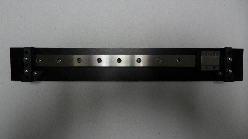
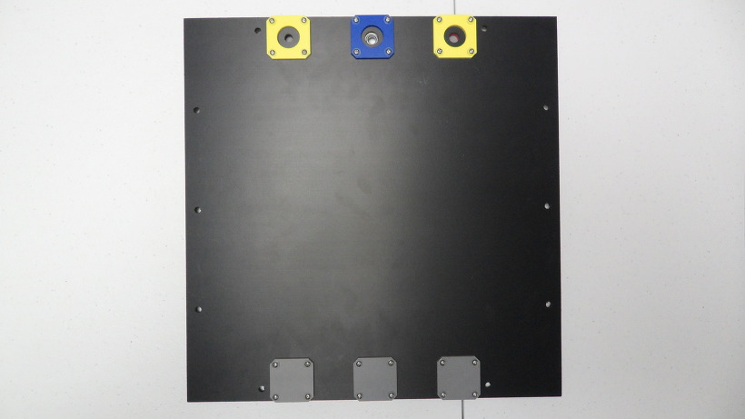
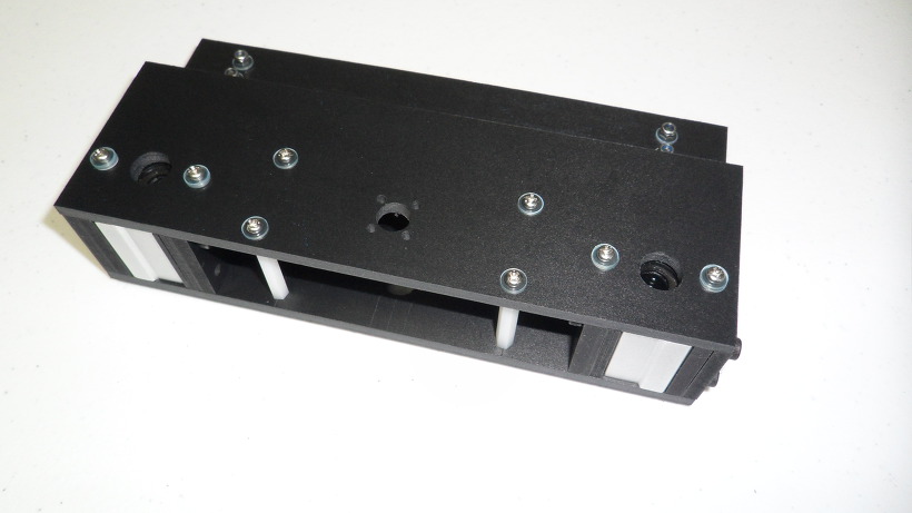
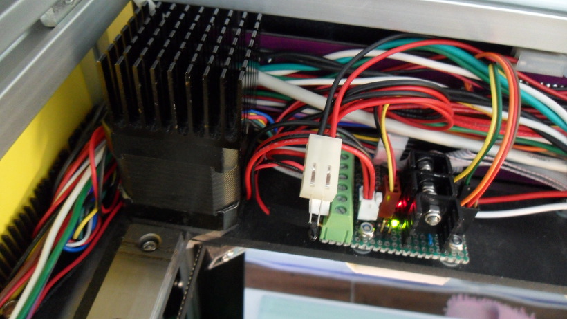
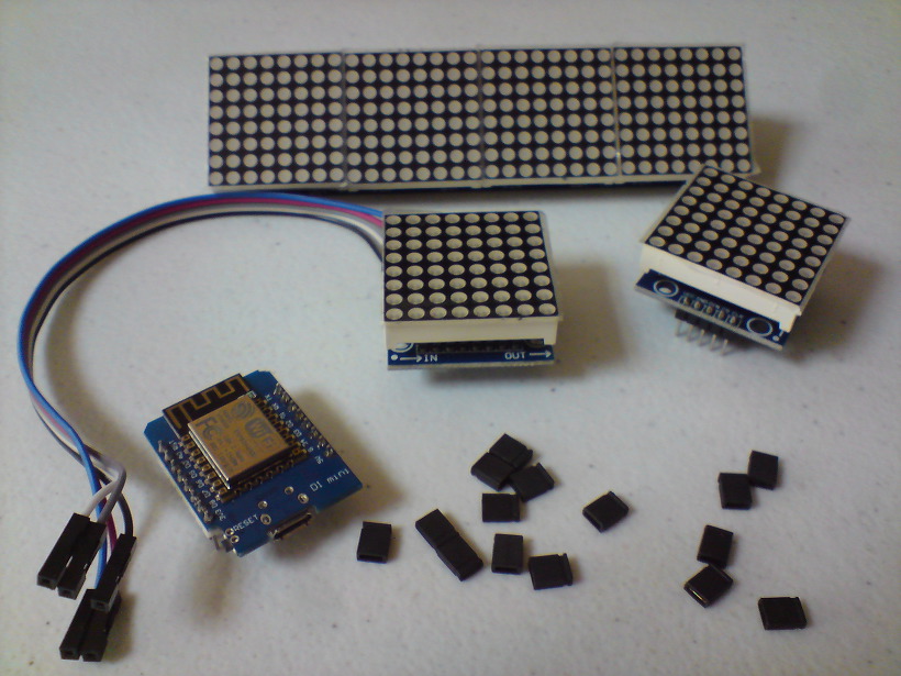
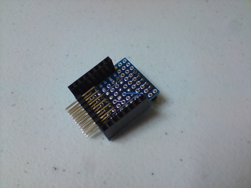
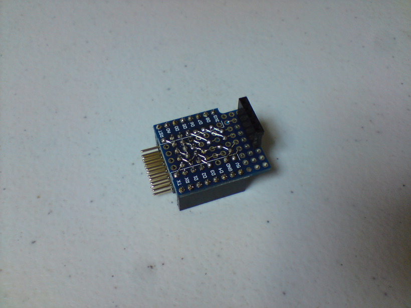
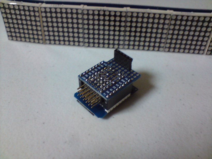
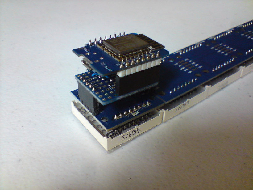
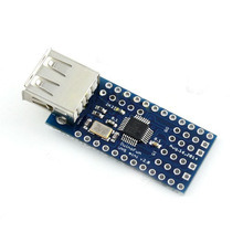
USB Host를 적용하여 Bluetooth로 직접 연결하는 방식이기 때문에 구성은 매우 간단합니다.

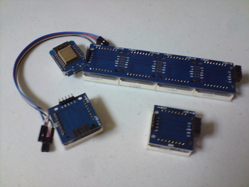
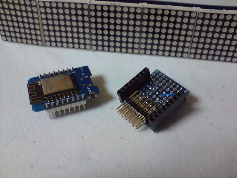
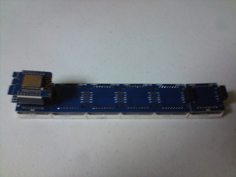
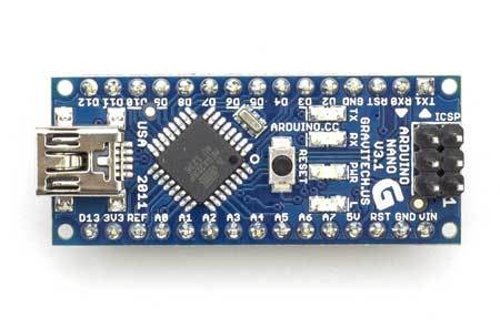
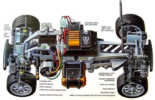
Arduino는 Nano를 사용하였고 USB Host Shield와 연결하기 위해 Mother Board를 하나 꾸며보았습니다.
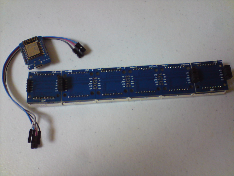
기능도 조금 추가했습니다.

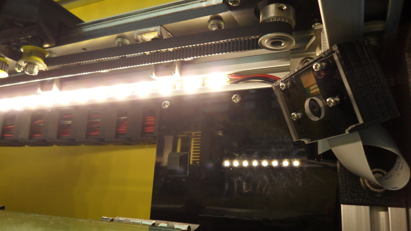
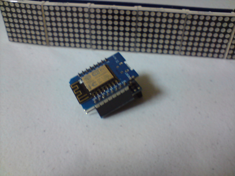
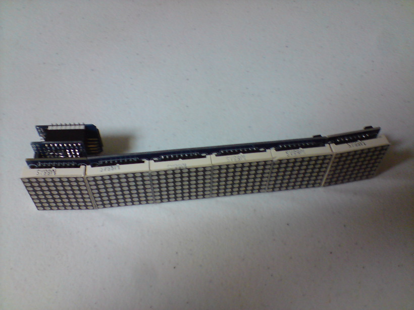
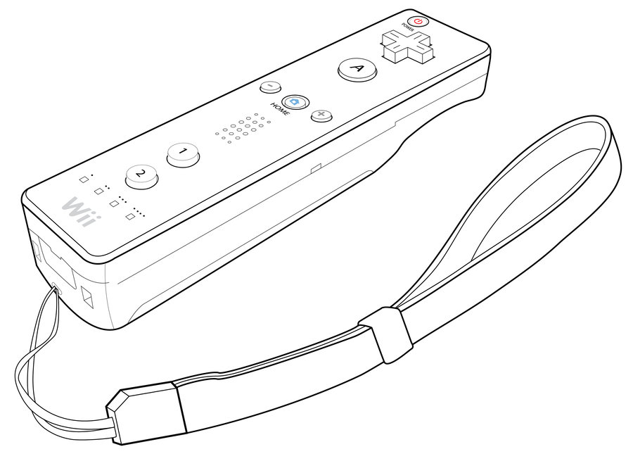
바나나를 던지거나 하지는 못하지만 “A” 버튼을 누르면 레이저가 발사되듯이 Fire LED가 켜지도록 하였고 “+” 버튼은 Head Light, “-” 버튼은 Back Light로 사용할 수 있도록 하였습니다.

그리고 좌우방향 버튼으로도 Steering이 가능하도록 하였습니다.

 Arrow Up  Left steering
 Arrow Down  Right steering
 Arrow Left  Gear Down
 Arrow Right  Gear Up
 A  Fire & Shutting
 B  –
 +  Head Light
 –  Back Light
 1  Backward
 2  Forward
 Home  Throttle mode change

하드웨어 (Hardware)

송신기 (Transmitter)

  • Wii 리모컨 (Wiimote)

수신기 (Reciver)

  • Arduino Nano

  • USB Host Shield
  • Bluetooth USB 어댑터 (Dongle)

  • DIY Mother Board


통신 거리는 Bluetooth 특성상 대략 10m 정도 밖에 안될 거라고 예상합니다만 그 이상도 충분합니다.


RC Car

  • Tamiya M-03

소프트웨어 (Software)

Arduino 용 라이브러리와 스케치를 포함한 파일은 github 에 있습니다.
이 라이브러리는 Richard Ibbotson이 만든 코드 wiiblue.pde 을 기반으로하고 있습니다.

샘플 스케치 (Sketch)

TwoWheelSterringWii.ino

#include “WiiRemote.h”

#include <MemoryFree.h>

#include <Servo.h>

#define PIN_STEERING_SIGNAL        2

#define PIN_ESC_SIGNAL             4

#define PIN_HEAD_LIGHT_SIGNAL     14

#define PIN_BACK_LIGHT_SIGNAL     15

#define PIN_FIRE_SIGNAL           17

#define PIN_STEERING_SELECT       16

#define SERIAL_DEBUG               0    // 0: active mode, 1: serial debug mode

enum eAngle

{

STEERING_ANGLE_MAX           = 165,   // to right

STEERING_ANGLE_CENTER        = 90,

STEERING_ANGLE_MIN           = 15,    // to left

STEERING_ANGLE_STEP          = 5,

STEERING_ANGLE_MAX_INVERT    = 165,   // to right

STEERING_ANGLE_CENTER_INVERT = 90,

STEERING_ANGLE_MIN_INVERT    = 15,    // to left

THROTTLE_ANGLE_MAX           = 160,   // 80,

THROTTLE_ANGLE_CENTER        = 90,

THROTTLE_ANGLE_MIN           = 10,

};

enum eServoPulse

{

SERVO_PULSE_MAX              = 2400,  // to left

SERVO_PULSE_NEUTRAL          = 1550,  // 1500 Futaba compatible, 1.55msec

SERVO_PULSE_MIN              = 600,   // to right

SERVO_PULSE_MAX_INVERT       = 600,   // to right

SERVO_PULSE_NEUTRAL_INVERT   = 1450,  // 1460 Futaba compatible, 1.55msec

SERVO_PULSE_MIN_INVERT       = 2400,  // to left

};

enum eESCPulse

{

/*

*  Futaba timing

*

*  0us     1072us         1522us          1922us

*   +———*————+-*-+————-*

*   |   n/a   |   forwad   |d|d|   Reverse   |

*   +———*————+-*-+————-*

*          Max Forwad     Neutral         Max Reverse

*

*   d: dead zone, +10us and -10us

*/

ESC_PULSE_NEUTRAL     = 1522,

ESC_PULSE_BRAKE       = 1600,

ESC_PULSE_FWD_MAX     = 800,   //1200, // 1072

ESC_PULSE_FWD_MIN     = 1510,

ESC_PULSE_FWD_3RD     = (ESC_PULSE_FWD_MIN – 240),

ESC_PULSE_FWD_2ND     = (ESC_PULSE_FWD_MIN – 160),

ESC_PULSE_FWD_1ST     = (ESC_PULSE_FWD_MIN – 80),

ESC_PULSE_REV_MAX     = 1700,  // 1922

ESC_PULSE_REV_FIX     = 1650,

ESC_PULSE_REV_MIN     = 1600,

};

enum eGear

{

GEAR_1ST = 1,

GEAR_2ND = 2,

GEAR_3RD = 3,

};

WiiRemote wiiremote;

Servo SteeringServo;

Servo ESC;

void setup()

{

#if SERIAL_DEBUG

Serial.begin(115200);

Serial.print(“\r\nfreeMemory() reports: “);

Serial.print(freeMemory(), DEC);

Serial.println(“Serial connect…”);

#endif

SteeringServo.attach(PIN_STEERING_SIGNAL);

SteeringServo.writeMicroseconds(SERVO_PULSE_NEUTRAL);

ESC.attach(PIN_ESC_SIGNAL);

ESC.writeMicroseconds(ESC_PULSE_NEUTRAL);

pinMode(PIN_HEAD_LIGHT_SIGNAL, OUTPUT);

pinMode(PIN_BACK_LIGHT_SIGNAL, OUTPUT);

digitalWrite(PIN_HEAD_LIGHT_SIGNAL, LOW);

digitalWrite(PIN_BACK_LIGHT_SIGNAL, LOW);

pinMode(PIN_FIRE_SIGNAL, OUTPUT);

digitalWrite(PIN_FIRE_SIGNAL, LOW);

pinMode(PIN_STEERING_SELECT, INPUT);

digitalWrite(PIN_STEERING_SELECT, LOW);

wiiremote.init();

/*

unsigned char wiiremote_bdaddr[6] = {0x00, 0x1e, 0x35, 0xda, 0x48, 0xbc};

wiiremote.setBDAddress(wiiremote_bdaddr, 6);

wiiremote.setBDAddressMode(BD_ADDR_FIXED);

*/

#if SERIAL_DEBUG

Serial.println(“Wiimote connecting…”);

Serial.println(“Please press 1 button and 2 button simultaneously”);

#endif

}

void loop()

{

wiiremote.task(&myapp);

}

int steering_angle          = STEERING_ANGLE_CENTER;

int steering_angle_invert   = STEERING_ANGLE_CENTER_INVERT;

int old_steering_angle      = STEERING_ANGLE_CENTER;

bool analog_throttle        = false;  // false = use “One” button as throttle

int throttle_angle          = THROTTLE_ANGLE_CENTER;

int gear                    = GEAR_1ST;

int pulse_steering;

int pulse_esc;

bool fire                   = false;                  // fire

bool head_light             = false;                  // head light

bool back_light             = false;                  // back light

void myapp(void)

{

#if SERIAL_DEBUG

Serial.print(“\r\n”);

#endif

/* Steering */

steering_angle = getSteeringAngle();

steering_angle_invert = getSteeringAngleInvert();

if (digitalRead(PIN_STEERING_SELECT) == HIGH) {

pulse_steering = map(steering_angle,

STEERING_ANGLE_MIN, STEERING_ANGLE_MAX,

SERVO_PULSE_MAX, SERVO_PULSE_MIN);

SteeringServo.writeMicroseconds(pulse_steering);

} else {

pulse_steering = map(steering_angle_invert,

STEERING_ANGLE_MIN_INVERT, STEERING_ANGLE_MAX_INVERT,

SERVO_PULSE_MAX_INVERT, SERVO_PULSE_MIN_INVERT);

SteeringServo.writeMicroseconds(pulse_steering);

}

if (wiiremote.buttonPressed(WIIREMOTE_UP)) {

steering_angle = STEERING_ANGLE_MIN;

steering_angle_invert = STEERING_ANGLE_MIN_INVERT;

if (digitalRead(PIN_STEERING_SELECT) == HIGH) {

pulse_steering = map(steering_angle, STEERING_ANGLE_MIN, STEERING_ANGLE_MAX, SERVO_PULSE_MAX, SERVO_PULSE_MIN);

SteeringServo.writeMicroseconds(pulse_steering);

} else {

pulse_steering = map(steering_angle_invert, STEERING_ANGLE_MIN_INVERT, STEERING_ANGLE_MAX_INVERT, SERVO_PULSE_MAX_INVERT, SERVO_PULSE_MIN_INVERT);

SteeringServo.writeMicroseconds(pulse_steering);

}

} else if (wiiremote.buttonPressed(WIIREMOTE_DOWN)) {

steering_angle = STEERING_ANGLE_MAX;

steering_angle_invert = STEERING_ANGLE_MAX_INVERT;

if (digitalRead(PIN_STEERING_SELECT) == HIGH) {

pulse_steering = map(steering_angle, STEERING_ANGLE_MIN, STEERING_ANGLE_MAX, SERVO_PULSE_MAX, SERVO_PULSE_MIN);

SteeringServo.writeMicroseconds(pulse_steering);

} else {

pulse_steering = map(steering_angle_invert, STEERING_ANGLE_MIN_INVERT, STEERING_ANGLE_MAX_INVERT, SERVO_PULSE_MAX_INVERT, SERVO_PULSE_MIN_INVERT);

SteeringServo.writeMicroseconds(pulse_steering);

}

}

#if SERIAL_DEBUG

Serial.print(“\tServo=”);

Serial.print(pulse_steering);

#endif

/* Brake and Throttle */

if (wiiremote.buttonPressed(WIIREMOTE_ONE)) {

if (pulse_esc < ESC_PULSE_NEUTRAL) {

// moving forward before press “One”

brake();

pulse_esc = ESC_PULSE_NEUTRAL;

} else {

// while stopping or moving backward, keep moving backward

pulse_esc = ESC_PULSE_REV_FIX;

}

} else {

if (analog_throttle) {

throttle_angle = getThrottleAngle();

pulse_esc = map(throttle_angle,

THROTTLE_ANGLE_MIN, THROTTLE_ANGLE_MAX,

ESC_PULSE_FWD_MIN, ESC_PULSE_FWD_MAX);

} else if (wiiremote.buttonPressed(WIIREMOTE_TWO)) {

switch (gear) {

case GEAR_1ST:

pulse_esc = ESC_PULSE_FWD_1ST;

break;

case GEAR_2ND:

pulse_esc = ESC_PULSE_FWD_2ND;

break;

case GEAR_3RD:

pulse_esc = ESC_PULSE_FWD_3RD;

break;

default:

pulse_esc = ESC_PULSE_NEUTRAL;

break;

}

} else {

pulse_esc = ESC_PULSE_NEUTRAL;

}

}

ESC.writeMicroseconds(pulse_esc);

//delay(15);

#if SERIAL_DEBUG

Serial.print(“\tESC=”);

Serial.print(pulse_esc);

#endif

/* Throttle mode */

if (wiiremote.buttonClicked(WIIREMOTE_HOME)) {

analog_throttle = !analog_throttle;

if (analog_throttle) {

wiiremote.setLED(WIIREMOTE_LED4); // analog mode

} else {

wiiremote.setLED(WIIREMOTE_LED1); // fixed mode, 1st gear

gear = GEAR_1ST;

}

}

/* Shift up or down */

if (!analog_throttle) {

if (wiiremote.buttonClicked(WIIREMOTE_RIGHT)) {

shiftUp();

} else if (wiiremote.buttonClicked(WIIREMOTE_LEFT)) {

shiftDown();

}

}

/* Fire */

if (wiiremote.buttonPressed(WIIREMOTE_A)) {

digitalWrite(PIN_FIRE_SIGNAL, HIGH);

} else {

digitalWrite(PIN_FIRE_SIGNAL, LOW);

}

/* Head light LED */

if (wiiremote.buttonClicked(WIIREMOTE_PLUS)) {

head_light = !head_light;

if (head_light) {

digitalWrite(PIN_HEAD_LIGHT_SIGNAL, HIGH);

} else {

digitalWrite(PIN_HEAD_LIGHT_SIGNAL, LOW);

}

}

/* Back light LED */

if (wiiremote.buttonClicked(WIIREMOTE_MINUS)) {

back_light = !back_light;

if (back_light) {

digitalWrite(PIN_BACK_LIGHT_SIGNAL, HIGH);

} else {

digitalWrite(PIN_BACK_LIGHT_SIGNAL, LOW);

}

}

} // myapp

int getSteeringAngle(void)

{

double rad;

int deg;

rad = acos((double) wiiremote.Report.Accel.Y);

deg = (int) (rad * 180.0 / PI);

/* clipping */

if (deg > STEERING_ANGLE_MAX) { deg = STEERING_ANGLE_MAX; }

if (deg < STEERING_ANGLE_MIN) { deg = STEERING_ANGLE_MIN; }

return deg;

}

int getSteeringAngleInvert(void)

{

double rad;

int deg;

rad = acos((double) wiiremote.Report.Accel.Y);

deg = (int) (rad * 180.0 / PI);

/* clipping */

if (deg > STEERING_ANGLE_MAX_INVERT) { deg = STEERING_ANGLE_MAX_INVERT; }

if (deg < STEERING_ANGLE_MIN_INVERT) { deg = STEERING_ANGLE_MIN_INVERT; }

return deg;

}

int getThrottleAngle(void)

{

double rad;

double compensate_z;

int deg;

rad = asin((double) wiiremote.Report.Accel.Y);

compensate_z = (double) wiiremote.Report.Accel.Z / cos(rad);

rad = asin(compensate_z);

deg = (int) (rad * 180.0 / PI);

/* clipping */

if (deg > THROTTLE_ANGLE_MAX) { deg = THROTTLE_ANGLE_MAX; }

if (deg < THROTTLE_ANGLE_MIN) { deg = THROTTLE_ANGLE_MIN; }

return deg;

}

inline void brake(void)

{

ESC.writeMicroseconds(ESC_PULSE_BRAKE);

delay(15);

ESC.writeMicroseconds(ESC_PULSE_NEUTRAL);

delay(15);

}

inline void shiftUp(void)

{

if (gear < GEAR_3RD) {

gear++;

wiiremote.setLED( (WIIREMOTE_LED1 << (gear – GEAR_1ST)) );

}

}

inline void shiftDown(void)

{

if (gear > GEAR_1ST) {

gear–;

wiiremote.setLED( (WIIREMOTE_LED1 << (gear – GEAR_1ST)) );

}

}