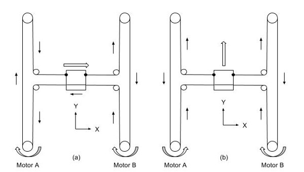
There is a family of 2 axis mechanisms called H-Bots. They use 2 motors on a single belt to generate motion in 2 axes. The most basic type is the classic H-Bot. ‘H’ comes from the outline of the belts.
Image from Galil Motion Control
The motors turn the same direction for motion in one axis. They turn opposite directions for motion on the other axis. If only one motor turns both axis will move evenly (like 45°, etc). All other angles are possible with the right drive ratios.
CoreXY
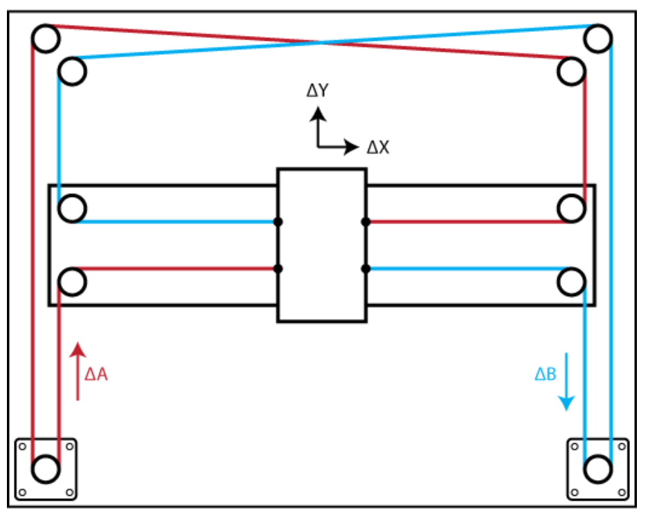
The H-Bot is simple, but imparts some twisting forces on the mechanism under some loads that work against accuracy. For example, look at left diagram in the image above. The belt is pulling down on the left side of the ‘H’ and up on the right side. This tries to twist the gantry if there is a resistance to the carriage movement in X. CoreXY addresses this by crossing the belts at one end. A longer belt does increase belt stretch issues though.
Image from CoreXY.com
T-Bots
T Bots are the simplest variety and work well with light loads.
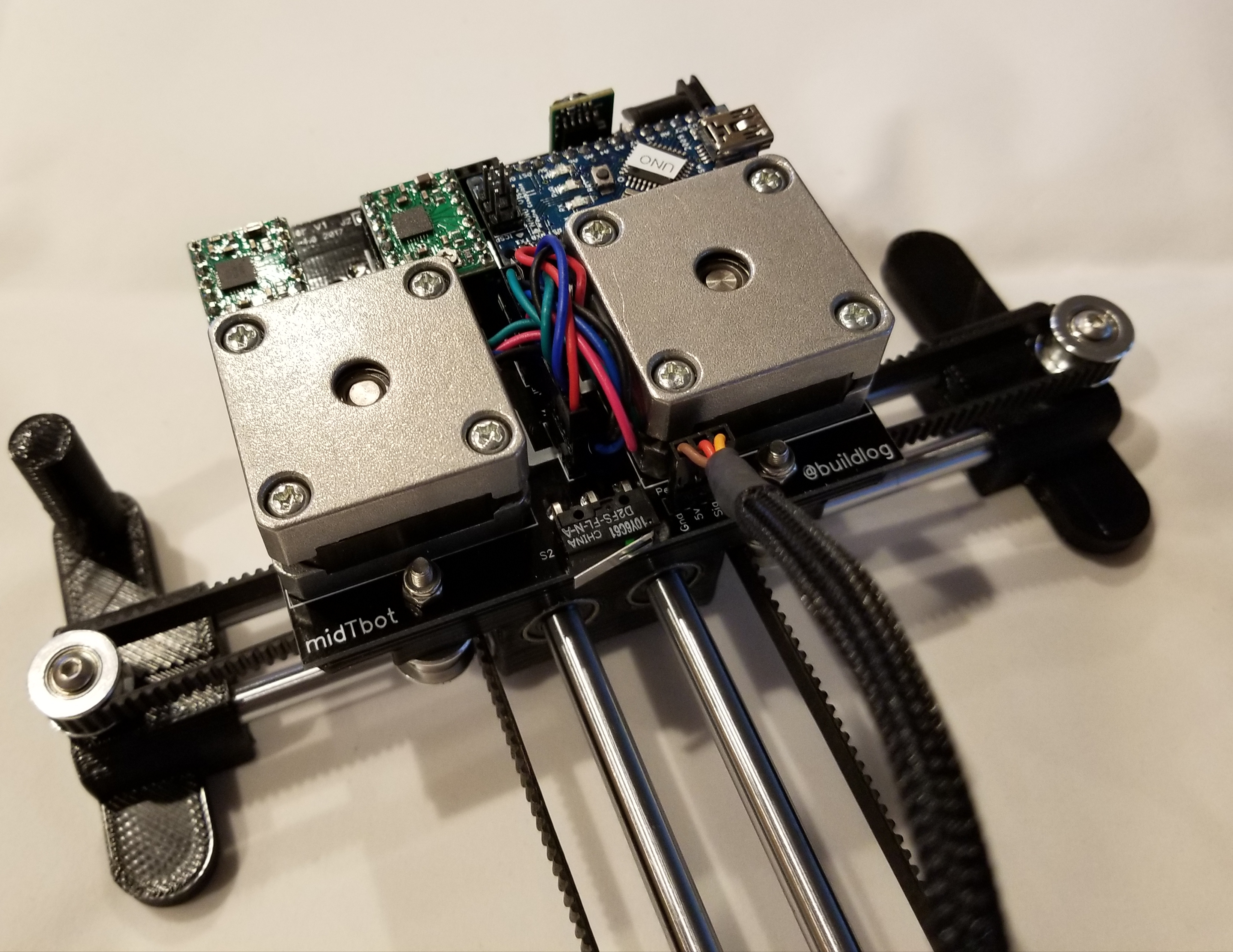
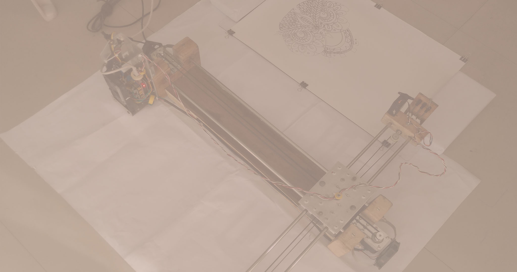
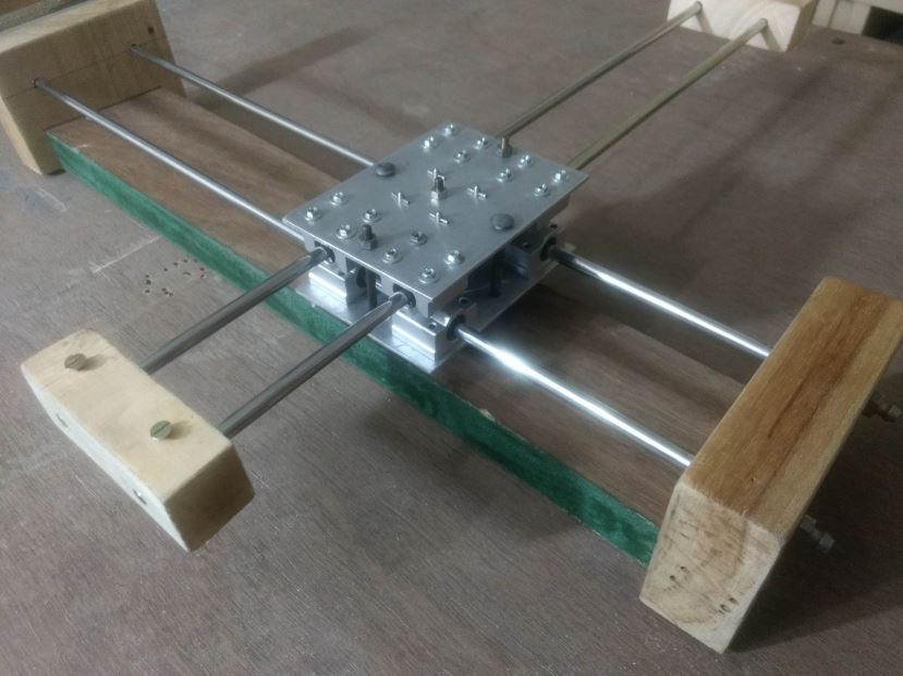
I was trying to make the smallest and simplest drawing machine with a reasonable work area. T-Bots are pretty simple, but the motors on the ends seemed to waste space. I also wanted integrated electronics. Moving the motors to the middle carriage seemed to solve a lot of these problems. It does add the motors to the mass of the moving parts, but only on one axis and they are directly over the linear bearings. It really has an elegant and smooth look to it. The midTbot name comes from middle mounted motors on a T bot. Here is an image of just the XY mechanism running.
Electronics
The ideal place for the electronics is right by the motors. This will reduce the wiring as much as possible. Putting the homing switches on the middle carriage would further clean up the wiring.
I designed a modular controller that mounts to the top of the middle carriage and under the motors.
The controller will soon be available on Tindie.
Scalability
It is very scalable because you only need to change the rod and belt lengths. No wiring needs to change. The middle mounted motors makes the platform very stable, but if allow the pen carriage to go too far forward, it could tip forward. I think you would need to extend the feet a little forward to counteract that.
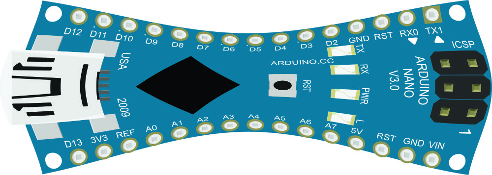
I recently compiled Grbl with the COREXY features enabled. To my surprise, the upload to my Nano failed because it did not have enough program space. I was surprised because the Nano and Arduino UNO use the same ATmega328p microcontroller. A little researched showed that they use different bootloaders.
Normally you a special programmer to program microcontrollers like Arduinos. You plug the programmer into the ICSP (In Circuit Serial Programming) pins on the microcontroller.
Bootloaders eliminate the need for this by putting the programmer right on the microcontroller. When you start (boot) the microcontroller, the bootloader runs first. It looks for someone trying to load a program. If it does not see that it switches to running the last uploaded program in another part of memory. The only penalty to this is that the bootloader needs to use a small amount of memory and it delays the start of your program a little. The total amount of memory available to the users is the flash memory size (32k for the …328P chip) minus the bootloader. The Nano and UNO use different bootloaders. The Nano uses a 2k bootloader and the UNO uses a 0.5k bootloader.
To get more memory of the Nano we have two options. We can use an ICSP programmer to use all of the memory. This removes the bootloader. The other option is to use a programmer to put the smaller UNO bootloader on the Nano.
Changing the Bootloader
You will need a programmer. you can get any of a dozen types of dedicated programmers, but you can also use another Arduino with a special sketch loaded on it.
How to use an UNO to Program a Nano
Use the Arduino IDE to upload the Arduino ISP (In-System Programmer) sketch to the UNO.
You will need 6 jumper wires. It is helpful to have a few colors to make it easy to verify the connections. They should have male pins on the UNO side and typically female sockets on the Nano side. These ribbon style jumpers are nice because you can peel off what you need and they have a lot of colors.
Arduino Uno (the programmer)
Nano I/O (the target)
Nano ICSP (the target)
5V
5V
5V
Gnd
Gnd
Gnd
D13
Reset
Reset
D11
D11
MOSI
D12
D12
MISO
D13
D13
SCK
Using I/O pins
Or using the ICSP Header
Install the Bootloader.
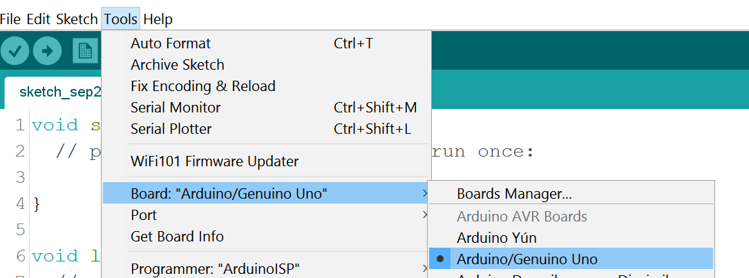
Be sure UNO is selected in the boards menu. This will make sure the UNO bootloader is used.
Change the programmer to Arduino ISP in the programmer menu. Remember to return it to current setting, typically AVR ISP, after you are done installing the bootloader.
Now select the Burn Bootloader menu. This will now install the UNO bootloader onto the Nano using the Arduino UNO as a programmer.
Using the Nano.
The Nano should now have the smaller UNO bootloader. When programming from now on, be sure to select UNO in the boards menu. The IDE will no longer be able program it as a Nano. You might want to mark the Nano so you remember this.
Extra Reading…..
How does the USB cable reboot the microcontroller?
In order to program the microcontroller via USB it needs to restart (boot). It does this using a special trick. Arduinos show up as a serial port (COM port). The Arduino only uses the Tx and Rx signals to transmit data. The USB adapter supports other RS232 signals. The DTR (Data Terminal Ready) signal is used to reset the Arduino. The DTR signal can be controlled by the program uploading the firmware.
Not shown in the schematic is a 1K pull up resistor on the reset pin near the ATmega328p. To reset the microcontroller you pull the reset pin to ground. The uploader program pulls the DTR signal low. The cap passes this change through, causing a reset, but the 1k pull up returns the reset back to the high (run) state. Remember: Capacitors pass changes (AC), but block a steady voltage (DC).
Why do they use different bootloaders?
I do not know the answer, but it probably due to the fact that they use different USB chips.
A cheap and easy to make CNC based DIY drawing robot
Introduction
Hi. Thank you for showing Interest in this project. This Project was my engineering’s final year capstone project. It took me a month to make this Project and I had fun building it. Below I am writing a step by step DIY guide to help you build your own CNC Drawing Robot. The guide is quite long with both text and video. I have given most details so that you will not feel any problem if you are new to making projects of this kind.
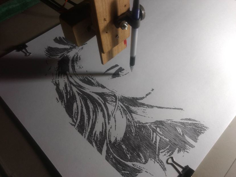
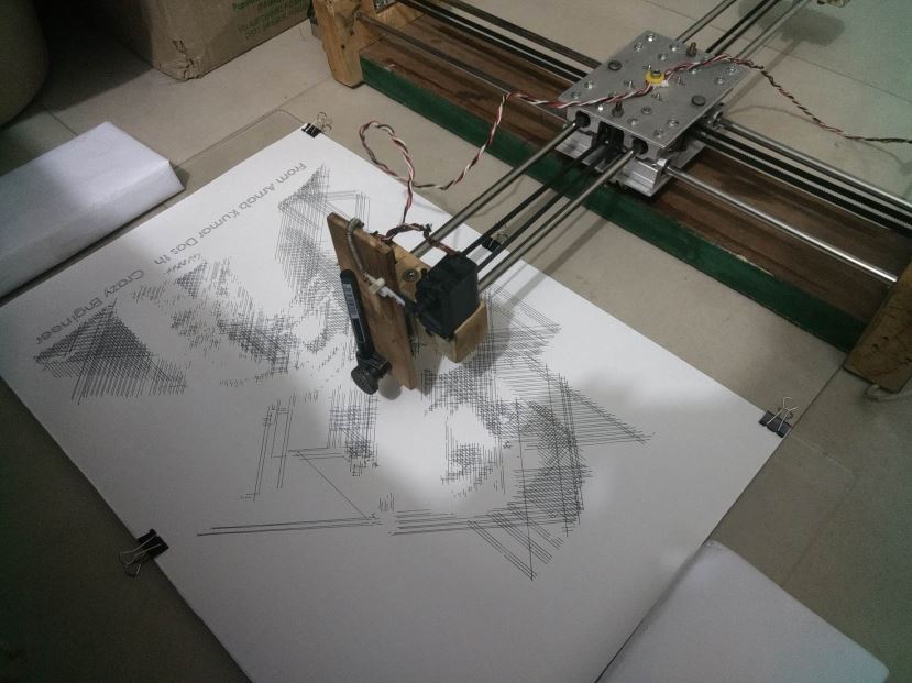
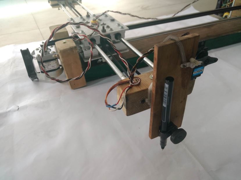
The Crazy Engineer’s Drawing Robot or Arduino GRBL CoreXY Servo Drawbot is a CNC based drawing robot. It is open source and open hardware based project. It uses Arduino UNO (Atmega328p) as the brain of the robot and a special GRBL firmware for G-Code Interpretation and motion control. It also uses a core [X, Y] Cartesian movement to control both X and Y axis. The Z axis is controlled by a servo motor to lift pen up and down.
Crazy Engineer’s Drawing Robot is a simple CNC Drawing Robot, capable of writing or drawing on almost any flat surface. It can write with gel pens, permanent markers, and a variety of other writing implements to handle an endless number of applications. Its writing head extends beyond the machine, making it possible to draw on objects bigger than the machine itself.
Suggested applications include:
• Decoration Drawing
• Computer artwork
• Technical drawing
• Notes and cards
• Writing signatures
• Signing diplomas and other certificates
• “Hand-written” lists
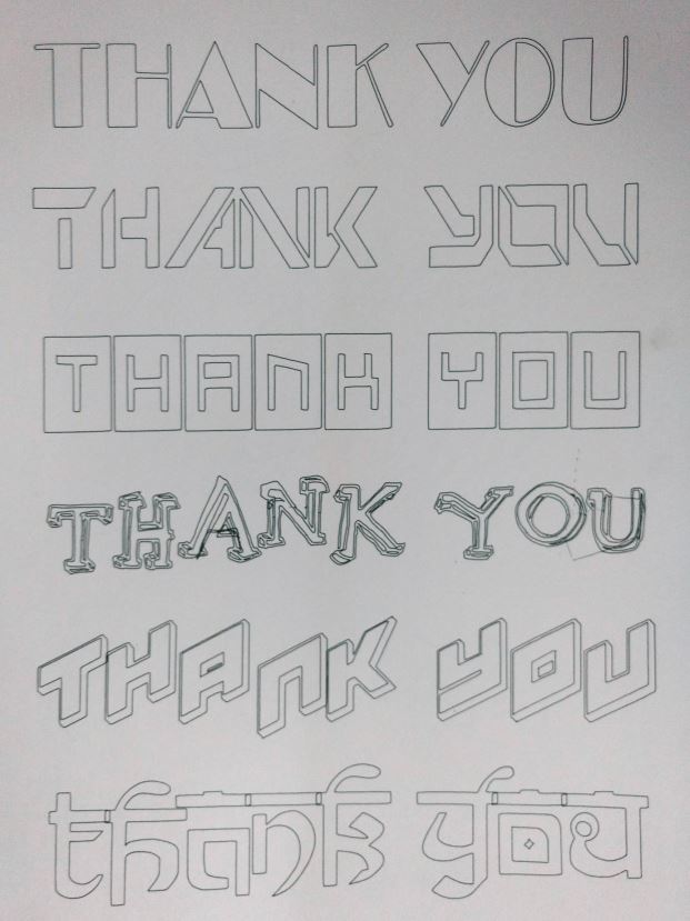
Vector Text
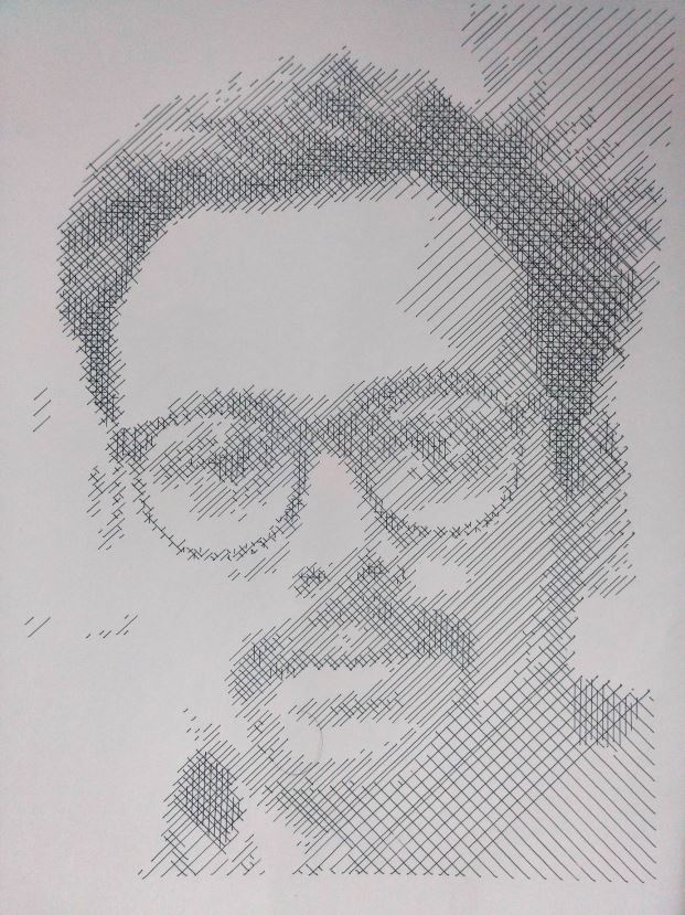
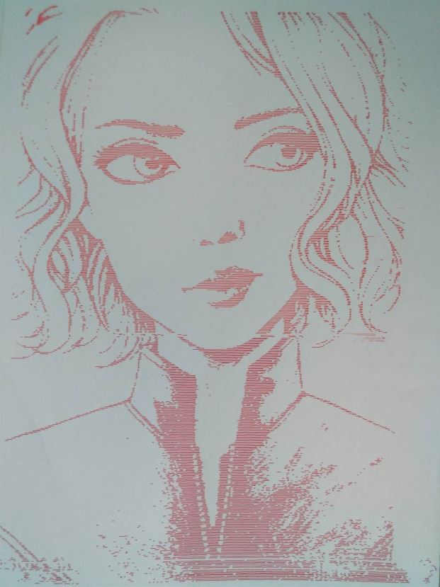
Raster Drawing
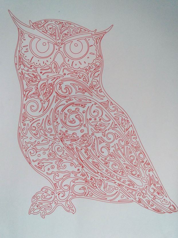
Vector Drawing
Vector Drawing
Project Motivation
When I was in my 2nd year of my engineering I did some research and came across the term CNC and I got fascinated by that. That time I came across a brand called Inventables that manufactures Desktop CNCs for Makers and low volume manufacturing. My early research was on CNC milling and drilling but making a CNC milling or drilling machine requires good investment and that is what I was lacking. Finally, I thought to make a CNC Drawing Robot that required relatively only a fraction of the cost of the CNC Milling machine.
If you Google DRAWBOT you will come across few interesting projects and product out of which :
Collectively I studied all of these and found it cool. But they were mostly using A4 paper so I made one for myself with the largest work area of all above. My Crazy Drawing Robot can handle paper as big as ARCH B.
The dreams of yesterday are the hopes of today and the reality of tomorrow. Science has not yet mastered prophecy. We predict too much for the next year and yet far too little for the next ten.
Project Comparison with AxiDraw
Crazy Engineer’s Drawbot is similar as well as different from AxiDraw:
• Crazy Engineer’s Drawbot is a Cartesian CoreXY movement (H-bot I think) similar to AxiDraw.
• Crazy Engineer’s Drawbot is based on Arduino, while AxiDraw is based on the EBB Driver board
• Crazy Engineer’s Drawbot has a large working area (45×38), like an ARCH B paper bigger than A3, while AxiDraw has a normal working area (30×20), like an A4 paper.
• Crazy Engineer’s Drawbot is Made of Wood to reduce cost, while AxiDraw is in metal (? this is not very clear watching the pictures)
• AxiDraw can write with a fountain pen, Crazy Engineer’s Drawbot not (yet)
• 2 x NEMA 17 Steppers 1.8 Degree Step 12v Torque more than 5kg/cm
• 4 x 8mm smooth rods (I used 8mm, will Suggest you to use 10mm/12mm) 600mm Long
• 8 x SC8UU (Will suggest u to use SC10UU/SC12UU)
• 2 x 20-Tooth GT2 pulleys
• 10 x F623ZZ Bearings (I used Plastic Pulleys to reduce cost)
• 1 x Micro Servo SG90 (Later I Used a Bigger Servo for Quality)
• 1 x Arduino UNO
• 1 x CNC Shield V3
• 2 x Pololu Step Sticks A4988 Stepper Driver
• 1 x GT2 Belt (3 meters long)
• 1 x Hard Wood 1mx20cmx4cm
• 8 x 30mm M3 screws with nuts
• 3 x BLDC Fan (Not Necessary if you are not in tropical climate)
• 1 x Aluminium Sheet 3mm
• 20 x 1 Inch Screw m4
• 20 x 3 Inch Screw M4
• 1 x Inch Screw m3
• 1 x Wire 5m
• 1 x SMPS 12v 5A
• 20 x Washers M4
• 6 x 4 Inch Screw M3
• 1 x Soldering Wire
• 1 x Solder
• 1 x Jig Saw
• 1 x Jig Saw Blade for wood cutting
• 1 x USB Wire
• 4 x Special Liquid ink PEN of multiple colour
• 5x Ferrite Core
• Miscellaneous Tools and Components
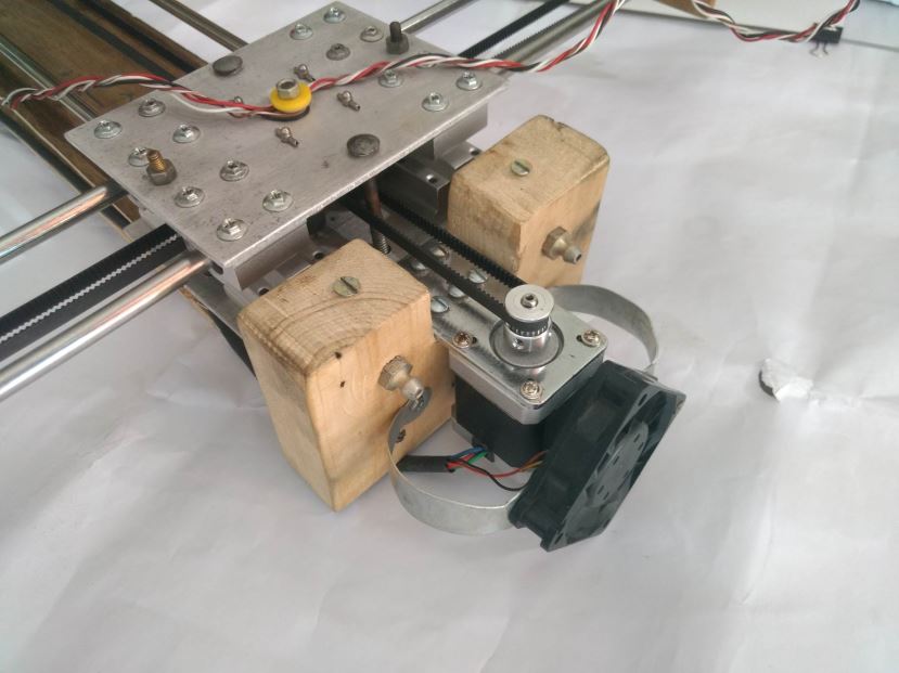
Core[X,Y]
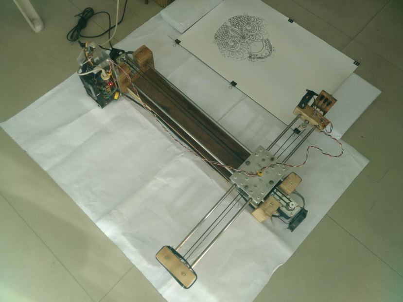
Core[X,Y] makes things easy and have added advantage in my build. CoreXY is a technique of motion control in 2D axis using a single continuous belt for both the axes. Design Advantage: The Design of the Drawing Robot is Compact as the Y axis motor as well as X axis motor is also on the main chassis, which keeps the centre of gravity closer to the chassis. So reduces machine weight as you can now use lighter rods and mechanism on the X axis as now it doesn’t have to carry the heavy stepper motor. Fast: CoreXY believe in speed. CoreXY’s (mostly) parallel kinematics mean that the motors, typically the largest source of inertia on a DIY-grade stage, are stationary. This permits rapid accelerations. Simple: CoreXY can be implemented with only three structural plates, all of which can nest during fabrication. Flexible: Whether your medium is fabric or aluminium, the principle behind CoreXY permits motion stages to be rendered in a variety of materials and a wide range of sizes.
CoreXY Working
Building The CNC’s Body
Build Process
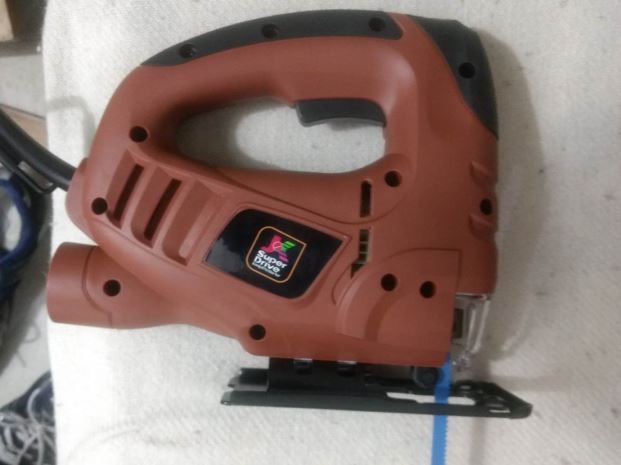
JK Super Drive Jig Saw Used for All Cutting
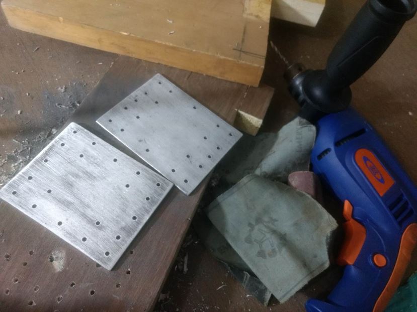
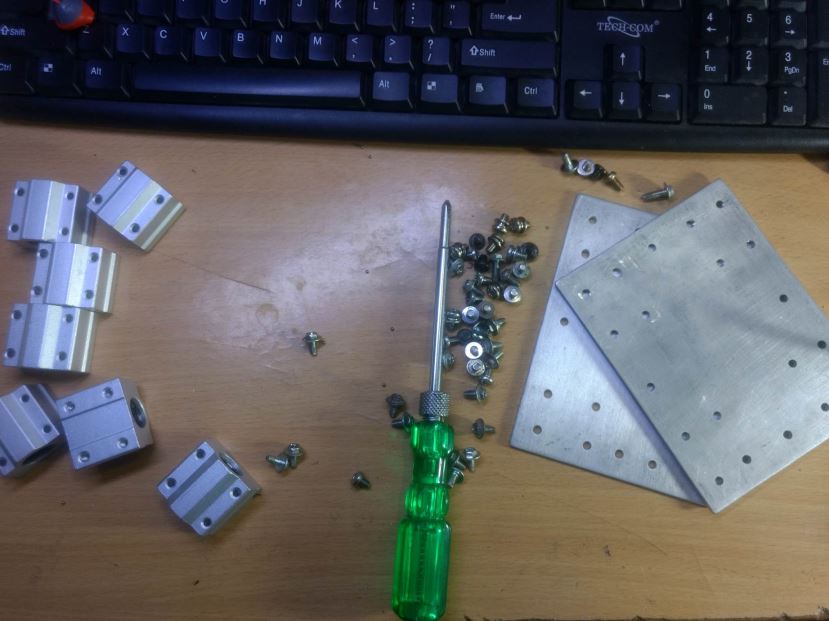
JK 13mm Drill with Al Plates
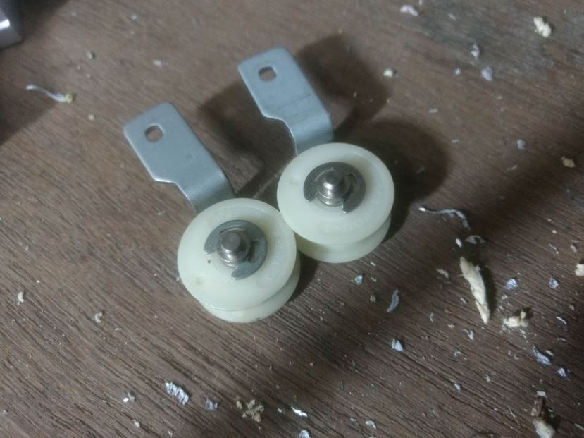
Plastic Pulleys
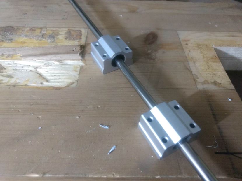
Linear Bearings with Shaft
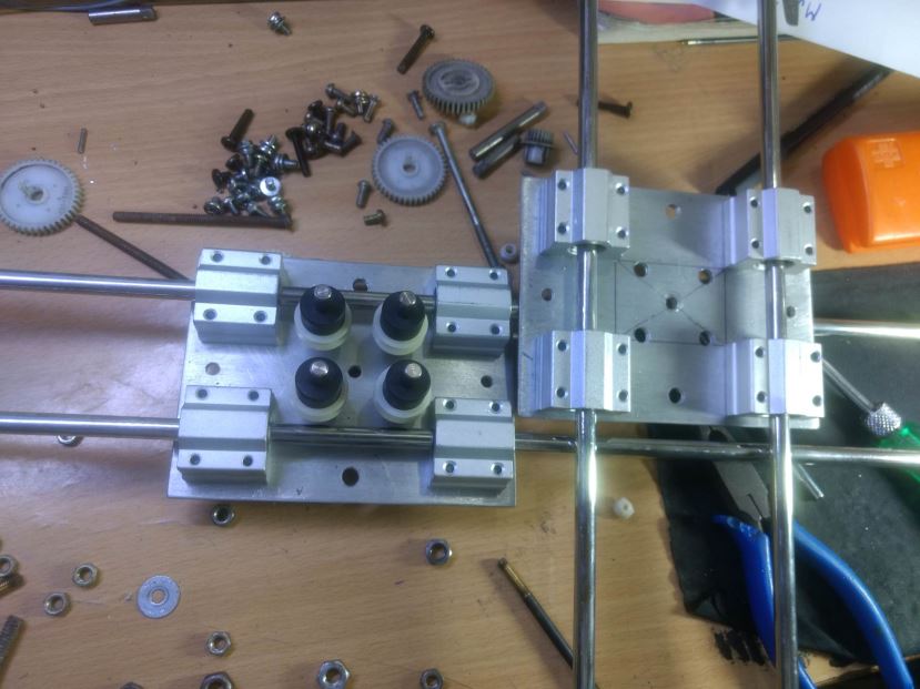
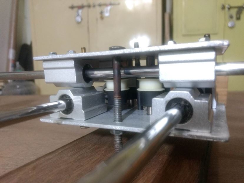
Assembling the bearings
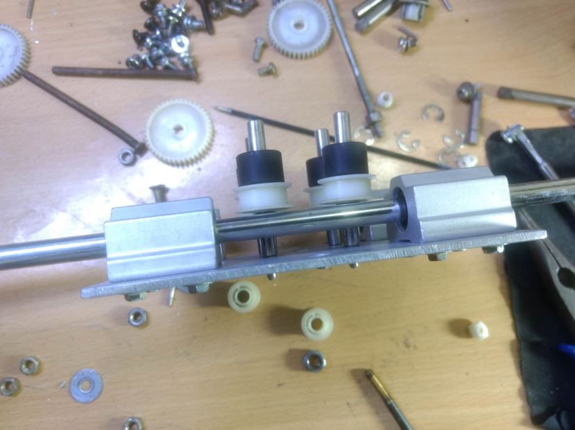
Pulleys in Central Carriage Assembly
Pulleys in Central Carriage Assembly
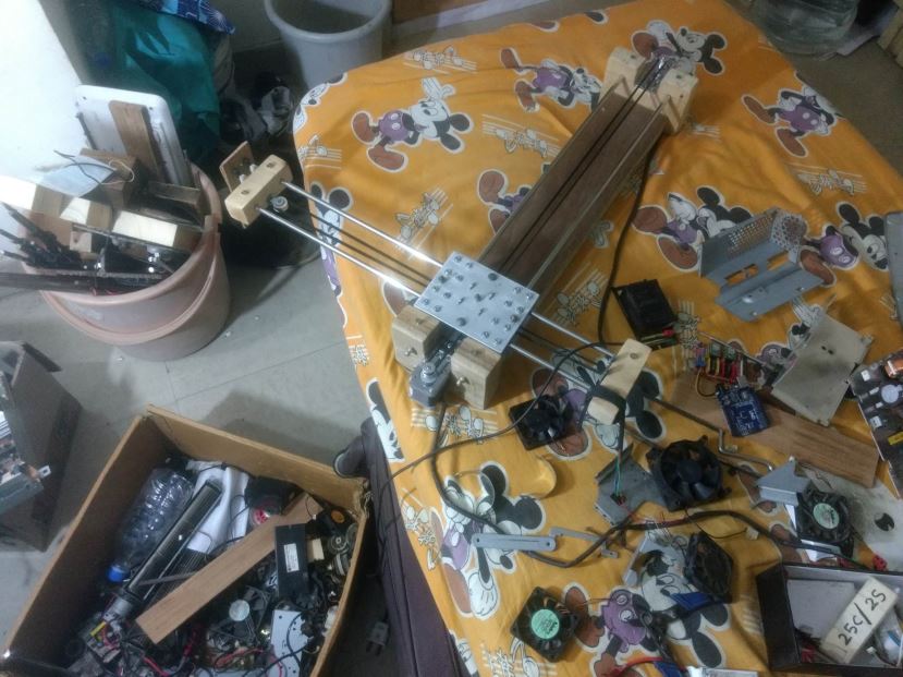
X and Y Axis Before Mounting on Chassis
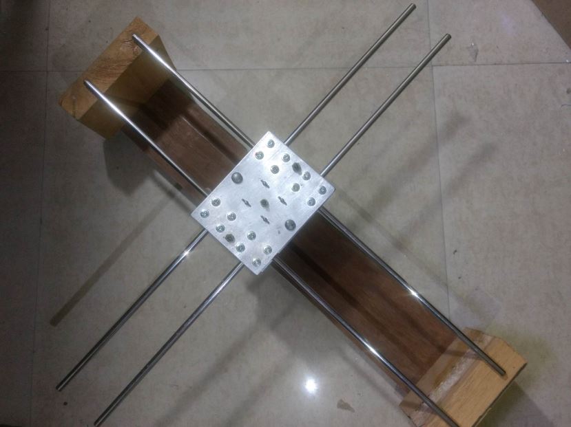
X and Y Axis After Mounting on Chassis
X and Y Axis After Mounting on Chassis
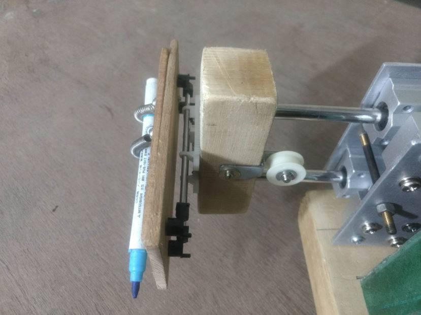
Pen Holder Bottom View
Pen Holder Components
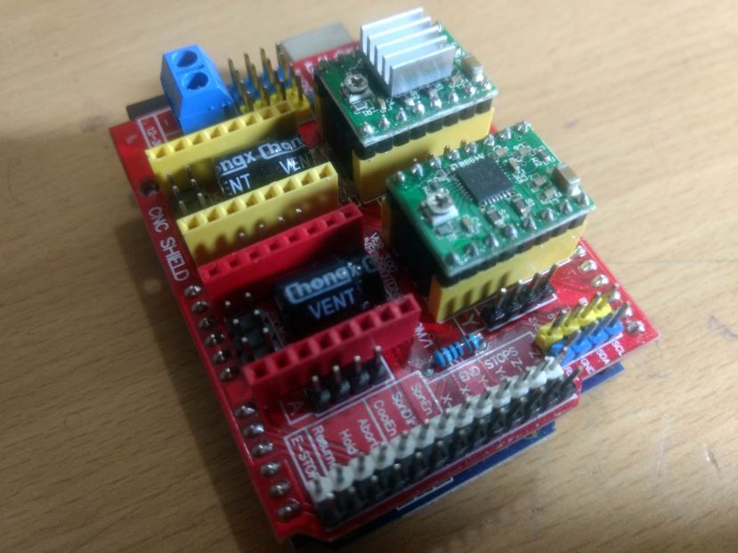
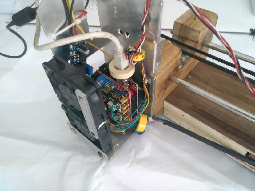
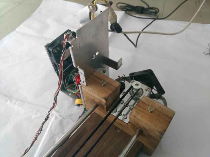
Arduino With CNC Shield
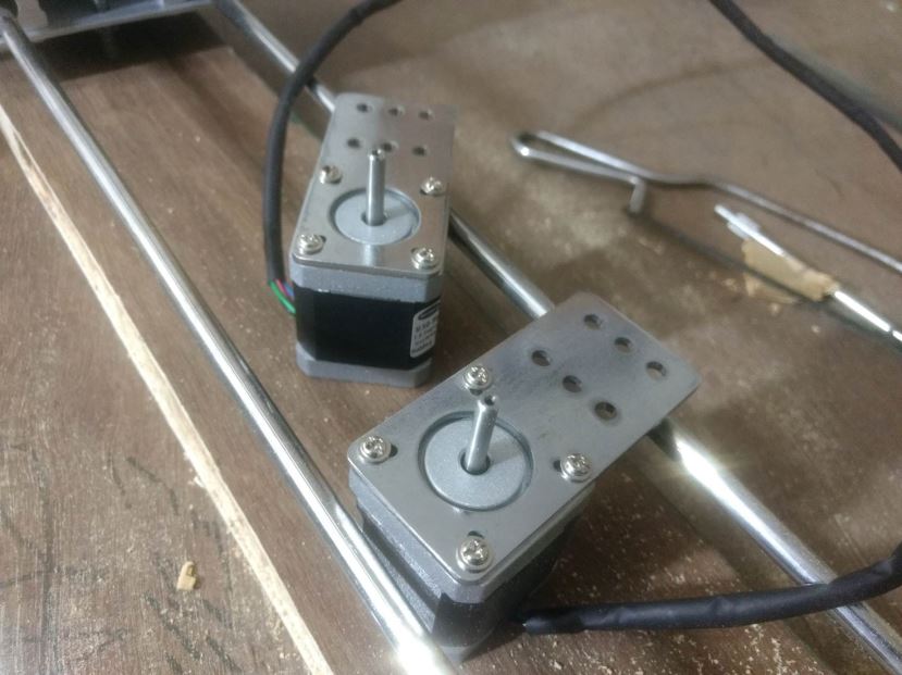
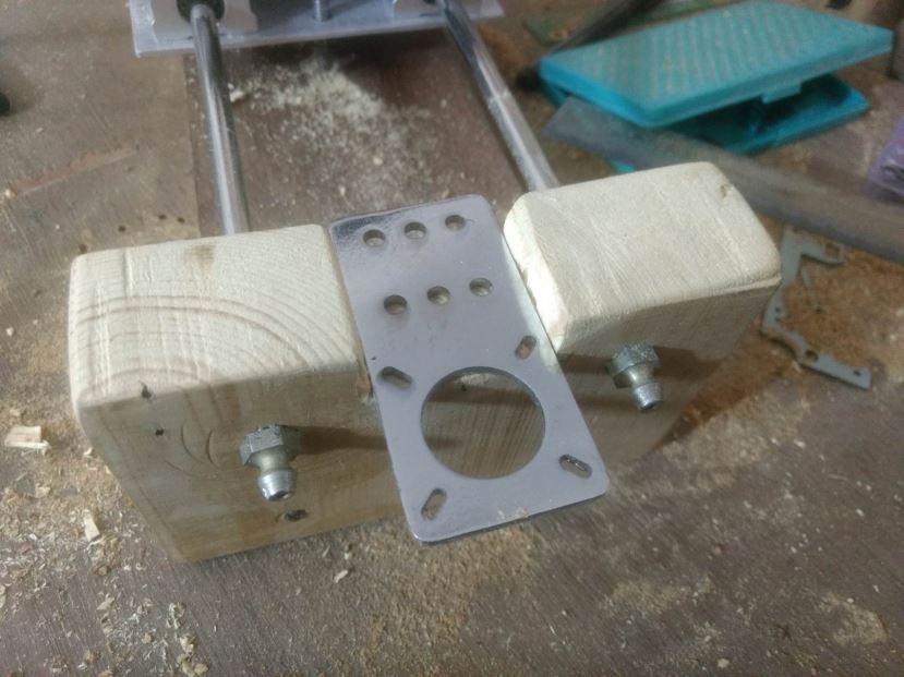
5.5Kgcm Stepper with Clamps
Stepper being Mounted on Chassis
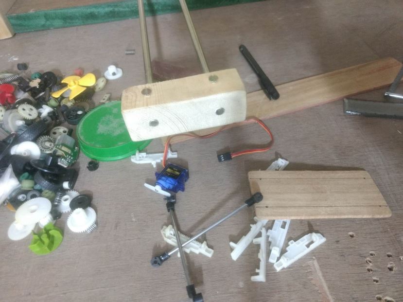
Mess During the Project Making
Raster Drawing Drawing Crazy Engineer’s Drawbot
Vector Drawing Crazy Engineer’s Drawbot
After Drawing Completion
Arduino UNO With BLDC Fans and Stepper Driver
Stepper Motor With BLDC Fan
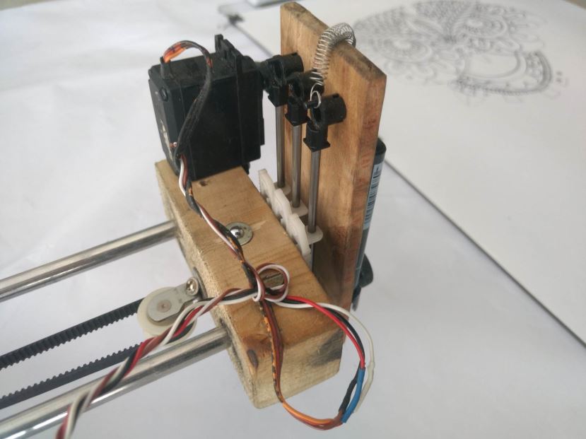
Pen Holder
Pen Holder WIth Servo Motor
Back Side of Heat Sink
Arduino Firmware Installation
This project is using a modified version of GRBL 0.9i Firmware that is . I have modified to enable CoreXY configuration and also enabled servo motor operation on pin D11. The servo motor will raise and lower the pen using Machine Code M03 and M05. (Will explain later in detail). So in Z axis no Stepper Motor is required to pull the pen.
Grbl-coreXY-servo is a no-compromise, high performance, low cost alternative to parallel-port-based motion control for CNC milling. It will run on a vanilla Arduino (Duemillanove/Uno) as long as it sports an Atmega 328p.
The controller is written in highly optimized C utilizing every clever feature of the AVR-chips to achieve precise timing and asynchronous operation. It is able to maintain up to 30kHz of stable, jitter free control pulses.
It accepts standards-compliant G-Code and has been tested with the output of several CAM tools with no problems. Arcs, circles and helical motion are fully supported, as well as, all other primary G-Code commands. Macro functions, variables, and most canned cycles are not supported, but we think GUIs can do a much better job at translating them into straight G-Code anyhow.
Grbl-coreXY-servo includes full acceleration management with look ahead. That means the controller will look up to 18 motions into the future and plan its velocities ahead to deliver smooth acceleration and jerk-free cornering.
• Licensing: Grbl is free software, released under the GPLv3 license.
After downloading you have to flash the Arduino Uno with the firmware.
Here are the Steps:
NOTE: Before starting, delete prior Grbl library installations from the Arduino IDE. Otherwise, you’ll have compiling issues! On a Mac, Arduino libraries are located in ~/Documents/Arduino/libraries/. On Windows, it’s in My Documents\Arduino\libraries.
2. Launch the Arduino IDE
• Make sure you are using the most recent version of the Arduino IDE!
3. Load Grbl into the Arduino IDE as a Library
• Click the Sketch drop-down menu, navigate to Include Library and select Add .ZIP Library.
• IMPORTANT: Select the Grbl folder inside the grbl-coreXY-servo-master folder, which only contains the source files and an example directory.
• If you accidentally select the .zip file or the wrong folder, you will need to navigate to your Arduino library, delete the mistake, and re-do Step 3.
4. Open the GrblUpload Arduino example
• Click the File down-down menu, navigate to Examples->Grbl, and select GrblUpload.
5. Compile and upload Grbl-coreXY-servo to your Arduino
• Connect your Arduino Uno to your computer.
• Make sure your board is set to the Arduino Uno in the Tool->Board menu and the serial port is selected correctly in Tool->Serial Port.
• Click the Upload, and Grbl-coreXY-servo should compile and flash to your Arduino! (Flashing with a programmer also works by using the Upload Using Programmer menu command.)
Software Tools Installation
We need multiple software and plugins for generating art-work, editing and sending G-Code to the CNC using Serial COM Port. I will be discussing installation in Windows platform but you can find all the software for Linux platform too. So the software we will be using are:
>>> Inkscape
[ Will be used to edit vector graphics and also to generate vector graphics (.svg) from .jpg, .png and .dxf formats ]
• Download the latest stable 32bit/64bit version according to your OS from Inkscape.org
• Installation is pretty simple and straight forward in Windows. In Linux you need to type some easy commands.
• Just do a Next Next and software will be installed.
>>> JTP Laser Tool Inkscape Plugin
[This Inkscape plugin will convert paths/drawing to G-Code for Vector Printing]
• Download the plugin from JTP Website
• Extract it using any good unzipping software.
• Put the contents of this .zip folder into the “inkscape\share\extensions” folder in installation directory.
• Once it is there it will show up under the “extensions” tab in Inkscape.
>>> Raster 2 Laser G-Code Generator
[This Inkscape plugin will convert paths/drawing to G-Code for Raster Printing]
• Download the plugin from my Git Hub Repository Raster 2 Laser
• Extract it using any good unzipping software.
• Put the contents of this .zip folder into the “Inkscape\share\extensions” folder in installation directory.
• Once it is there it will show up under the “extensions” tab in Inkscape.
>>> UGS Platform / UniversalGcodeSender
[ Will send G-Codes from laptop to Arduino UNO via USB Serial Port]
• Download and install the version of Java listed on the download page according to your OS and system configuration. Requires Java 8. Download Here
• Download UGS Platform UGS Download
• Extract it using any good unzipping software.
• In the extracted folders locate bin in the ugsplatform directory.
• On Windows run ugsplatform.exe or ugsplatform64.exe, on Linux or Mac OSX run ugsplatform.
• No need of any installation or build.
>>> Camotics
[ Will be used for visualizing G-Codes and simulation purpose]
• Download the latest version from Camotics
• Simple and fluid installation.
>>> Makelangelo Software
[Will be used to generate monochrome pattern art work from jpg, png and other formats that can be printed by single colour pen by CNC Drawing Machine]
• Download the Makelangelo Software from my Git Hub Repository Makelangelo-Software
• Extract it using any good unzipping software.
• Open the extracted folder and find Makelangelo10.jar file.
• Run the .jar file using Java 8 you have installed in previous steps.
>>> Inkscape Template File
[This template will be used according to the paper feeded to the Drawing Machine and will help in G-Code generation with exact dimension]
• Download the template from my Git Hub Repository Inkscape-Template
• Extract it using any good unzipping software.
• Open the extracted folder and find Makelangelo10.jar file.
Processing from Existing JPG/PNG Image in Inkscape
• Open Inkscape.
• Open the template you have downloaded in previous step according to your paper size.
• Click on File -> Import then select the JPG or PNG file from your drive and click open.
• Resize and position the image according to your page size.
• Image must be inside the boundaries of the page or G-code will not be generated properly.
• Right Click on the image and select Trace Bitmap.
• Select any of the Three Option [ Experiment and You will know the working] Brightness Cutoff, Edge Detection, Colour Quantization.
• Change the threshold according to the details you want in the drawing.
• Click on Update.
• Click OK and close the window.
• The Vector Bitmap will be overlapping the original picture.
• Drag out the original picture and delete it. You are ready to generate G-code.
• Now See G-code Generation Step.
Processing from Custom Drawing in Inkscape
• Open Inkscape.
• Open the template you have downloaded in previous step according to your paper size.
• Start drawing or writing text inside the work area.
• Select all the objects by Ctrl+A shortcut.
• Group then together by Object -> Group from menu or by Ctrl+G shortcut.
• Then you have to convert object to path from menu Path -> Object To Path or by shortcut Shift+Ctrl+C. [ Important Step]
• Now See G-code Generation Step.
Generating Art Work from Image in Makelangelo Software
• Open Makelangelo Software running the .jar file.
• Click Open File and select the JPG/PNG file from your drive.
• Select the Conversion Style from the drop down menu. [ My fav is Crosshatch]
• Click ok.
• Click Save to file/SD Card and go to the location where you want to save.
• Put your file name and select DXF R12 File Format .DXF.
• Now run Inkscape and open the saved .DXF file with default settings.
• Resize it according to your need.
• Now See G-code Generation Step.
Raster G-code Generation
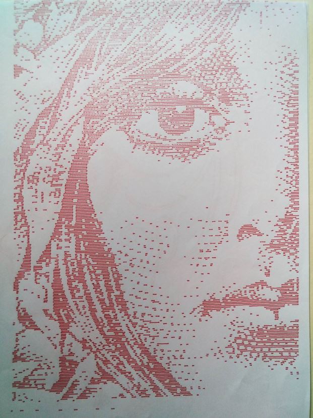
• In raster mode the machine will scan the whole drawing area from [0,0] till the end line by line. [Raster mode is slow and takes more time]. See the videos [Raster Drawing Girl’s Face Video 1] [Raster Drawing Girl’s Face Video 2]
• After converting all objects to path from previous step you are ready to generate your G-code.
• Now select all the paths that are inside the work area or use Ctrl+A.
• Click Extensions -> 305 Engineering -> Raster 2 Laser G-code Generator.
• Give Export Directory Path.
• Give File Name.
• Enable Numeric Suffix.
• Resolution means number of lines per mm, increasing will increase drawing time.
• Play with the options below like the RGB threshold.
• Set Engraving speed to 1500 or above.
• Select No Homing.
• Edit Laser ON to M03 S255.
• Edit Laser OFF to M05 S0.
• Deselect Preview, if selected no G-code will be generated.
• Click Apply. Wait and Enjoy. You are Ready to print now.
Vector G-code Generation
• In vector mode the machine will scan the only the drawing area where lines are there. [Vector mode drawing takes less time]. See the video [Vector Drawing PowerPuff Girls Video ]
• After converting all objects to path from previous step you are ready to generate your G-code.
• Now select all the paths that are inside the work area or use Ctrl+A.
• Click Extensions -> Generate laser G-code -> J Tech Photonics Laser Tool.
• Give Export Directory Path.
• Give File Name.
• Enable Numeric Suffix.
• Set All Units to mm.
• Set Laser speed to 1500 or above.
• Set Travel speed to 3000 or above.
• Select No Homing.
• Edit Laser ON to M03.
• Edit Laser OFF to M05.
• Deselect Preview
• Click Apply. Wait and Enjoy. You are ready to Print now.
GRBL Configuration and Setting Up Your Machine for the First Time
First, connect to Grbl using the serial terminal of your choice.
Set the baud rate to 115200 as 8-N-1 (8-bits, no parity, and 1-stop bit.)
Once connected you should get the Grbl-prompt, which looks like this:
Grbl 0.9i [‘$’ for help]
Type $ and press enter to have Grbl print a help message. You should not see any local echo of the $ and enter. Grbl should respond with:
The ‘$’-commands are Grbl system commands used to tweak the settings, view or change Grbl’s states and running modes, and start a homing cycle. The last four non-‘$’ commands are realtime control commands that can be sent at anytime, no matter what Grbl is doing. These either immediately change Grbl’s running behavior or immediately print a report of the important realtime data like current position (aka DRO).
$$ – View Grbl settings
To view the settings, type $$ and press enter after connecting to Grbl. Grbl should respond with a list of the current system settings, as shown in the example below. All of these settings are persistent and kept in EEPROM, so if you power down, these will be loaded back up the next time you power up your Arduino.
$x=val – Save Grbl setting
The $x=val command saves or alters a Grbl setting, which can be done manually by sending this command when connected to Grbl through a serial terminal program, but most Grbl GUIs will do this for you as a user-friendly feature.
To manually change e.g. the microseconds step pulse option to 10us you would type this, followed by an enter:
$0=10
If everything went well, Grbl will respond with an ‘ok’ and this setting is stored in EEPROM and will be retained forever or until you change them. You can check if Grbl has received and stored your setting correctly by typing $$ to view the system settings again.
Grbl’s default configuration is intentionally very generic to help ensure users can see successful motion without having to tweak settings. Generally, the first thing you’ll want to do is get your stepper motors running, usually without it connected to the CNC. Wire Grbl to your stepper drivers and stepper motors according to your manufacturer guidelines. Connect to Grbl through a serial terminal or one of many Grbl GUIs. Send some G1 or G0 commands to Grbl. You should see your stepper motor rotating. If you are having trouble with your stepper motors, try the following:
• Ensure everything is wired and powered correctly per your stepper driver manufacturer guidelines.
• If your steppers are mounted in your CNC already, ensure your axes move freely and don’t obviously bind. If you can’t easily tell, try removing your steppers and check if they run under no load.
• Ensure your stepper motors and axes linear mechanisms are all tight and secure. Small set screws on drivetrain components becoming loose is a very common problem. Re-tighten and try applying some non-permenant thread locker (Loctite blue) if it continually loosens.
• For more difficult issues, try the process of elimination to quickly isolate the problem. Start by disconnecting everything from the Arduino. Test if Grbl is operating ok by itself. Then, add one thing at a time and test.
• If your steppers are powered and making a grinding noise when trying to move, try lowering the ‘$’ acceleration and max rate settings. This sound is a sign that your steppers is losing steps and not able to keep up due too much torque load or going too fast.
• Grbl’s default step pulse settings cover the vast majority of stepper drivers on the market. While very uncommon, check these settings if you are still experiencing problems or have a unusual setup.
Next, you will need to make sure your machine is moving in the correct directions according to a Cartesian(XYZ) coordinate frame. Mount your stepper motors into your CNC, if you haven’t already done so. Send Grbl some motion commands, such as G91 G0 X1 or G91 G0 X-1, which will move the x-axis +1mm and -1mm, respectively. Check all axes. If an axis is not moving correctly, alter the $3 direction port mask setting to invert the direction.
If you are unfamiliar with how coordinate frames are setup on CNC machines, see this great diagram by LinuxCNC. Just keep in mind that motions are relative to the tool. So on a typical CNC gantry router, the tool will move rather than the fixed table. If the x-axis is aligned positive to the right, a positive motion command will move the tool to the right. Whereas, a moving table with a fixed tool will move the table to the left for the same command, because the tool is moving to the right relative to the table.
Finally, tune your settings to get close to your desired or max performance. Start by ensuring your $100,$101, and $102 axes step/mm settings are correct for your setup. This is dependent on your stepper increments, micro steps on your driver, and mechanical parameters. There are multiple resources online to show you how to compute this for your particular machine, if your machine manufacturer has not supplied this for you. Tweak your $11x acceleration and $12x max rate settings to improve performance. Set to no greater than 80% of absolute max to account for inertia and cutting forces. Set your $13x max travel settings if you plan on using homing or soft limits. It’s recommended to enter something approximately close to actual travel now to avoid problems in the future.
At this point, you’re pretty much ready to get going! Grbl can now move your CNC machine and run g-code jobs. If you need to add more features, such as limit switches for homing or hard limits or spindle/laser control. There are other Wiki pages to help you that. Good luck and have fun!
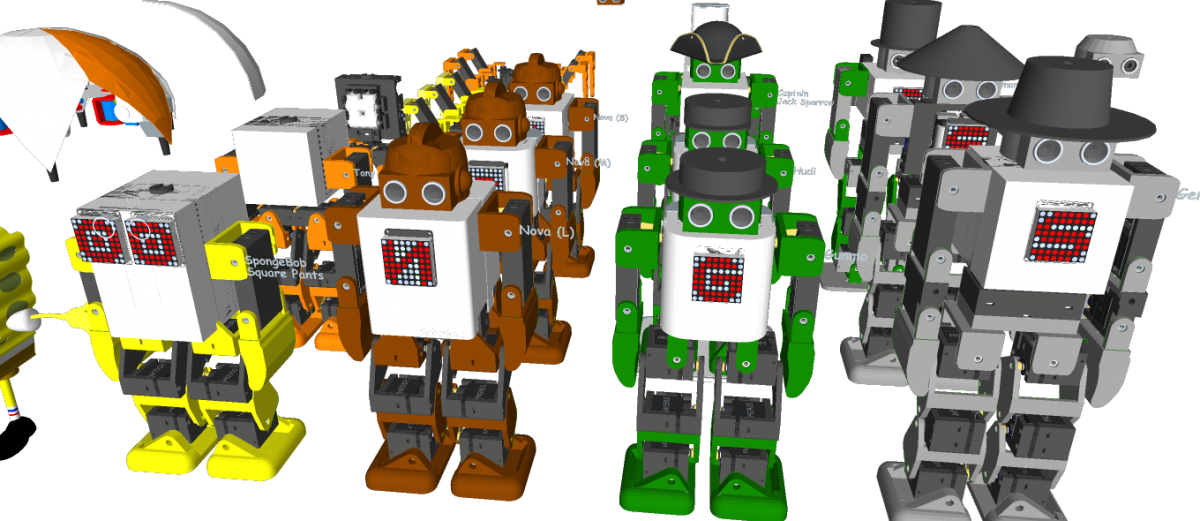
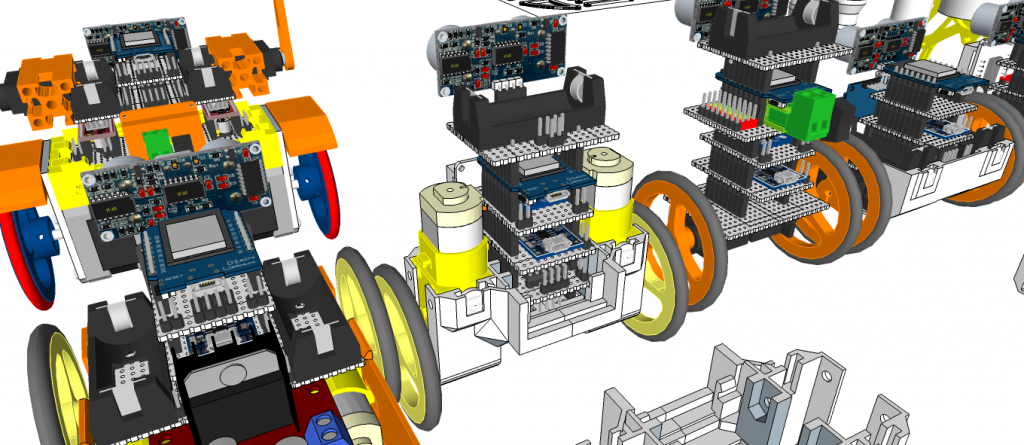
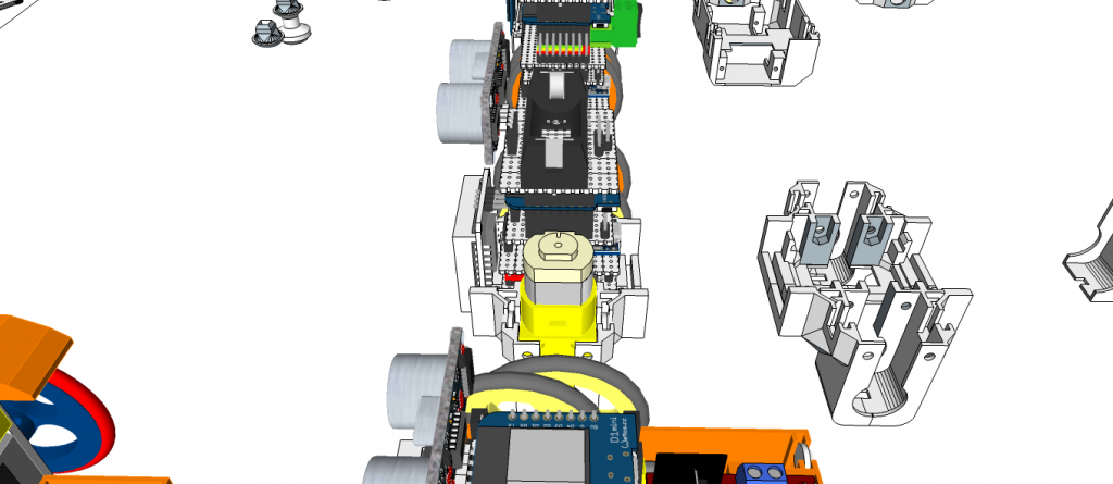
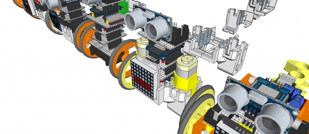
Robonoid is small sized bipedal walking robot The robot has 17 or 19, 24 freely moveable joints and servomotor in order to provide for a range of action and stable movements. Since it’s small in size, Robonoid can balance well and cope with basic movements such as walking and getting up. Also, intricate movements like roller skating and skateboarding are possible.
Robonoid is a wireless controllable robot You can control it by WiFi protocol through your PC and Smartphones. App for android and iOS are an especially intelligible UI. By using it, complicated operations can be controlled more easily.
Robonoid is a friendly robot Robonoid was named indicates a “simply shaped robot” that everyone imagines. Robonoid was designed by pursuing a simple appearance and simple functionality.
PSY – 135.7mm(W) x 258.39mm(H) x 100mm(D) – 17DOF
Jack – 135.7mm(W) x 305.62mm(H) x – 92,48mm(D) – 22DOF
Gentleman – 135.7mm(W) x 341.22mm(H) x – 78.5mm(D) – 22DOF
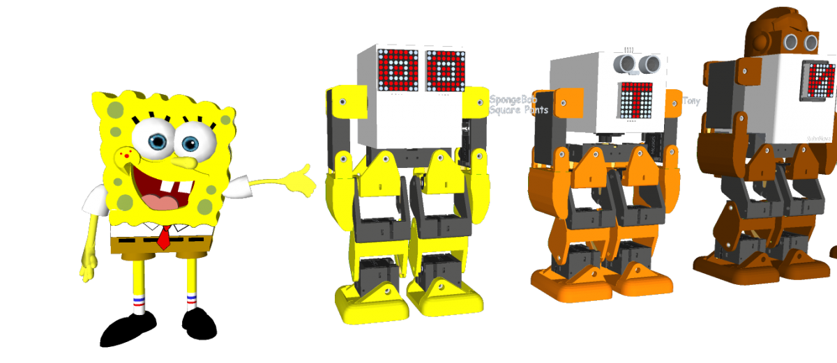
Tony – 135.7mm(W) x 265.5mm(H) x – 100mm(D) – 18DOF
SpongwBob – 135.7mm(W) x 230.0mm(H) x 100mm(D) – 16DOF
Hudi – 135.7mm(W) x 251.4mm(H) x 87mm(D) – 19DOF
Gunmo – 135.7mm(W) x 259.3mm(H) x 78.5mm(D) – 19DOF – https://youtu.be/qIZJZDcRpVw
Nova – 135.7mm(W) x 282.8mm(H) x 100mm(D) – 17DOF – https://youtu.be/kzfyKRzp_9I
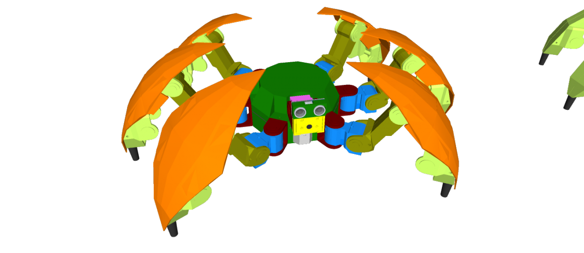
Hexapod S1 – DOM 352.83mm(WD) x 193.16mm(H) – 20DOF
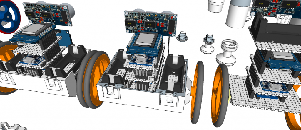
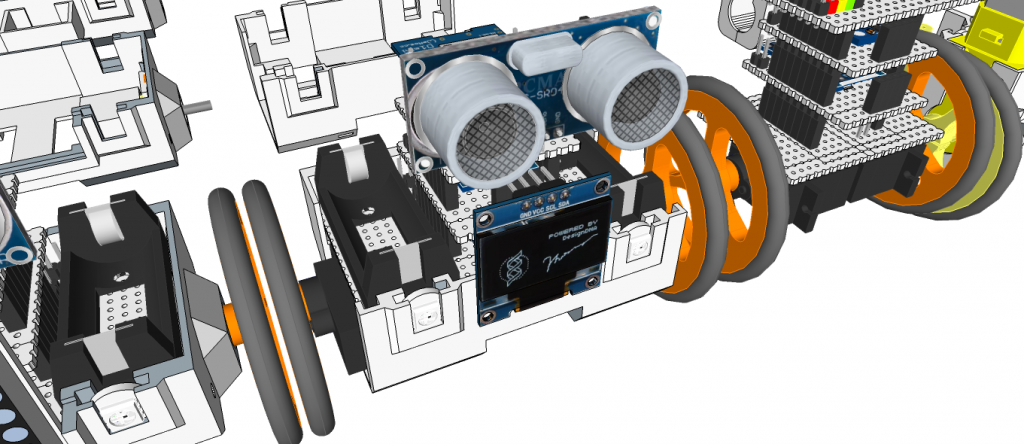
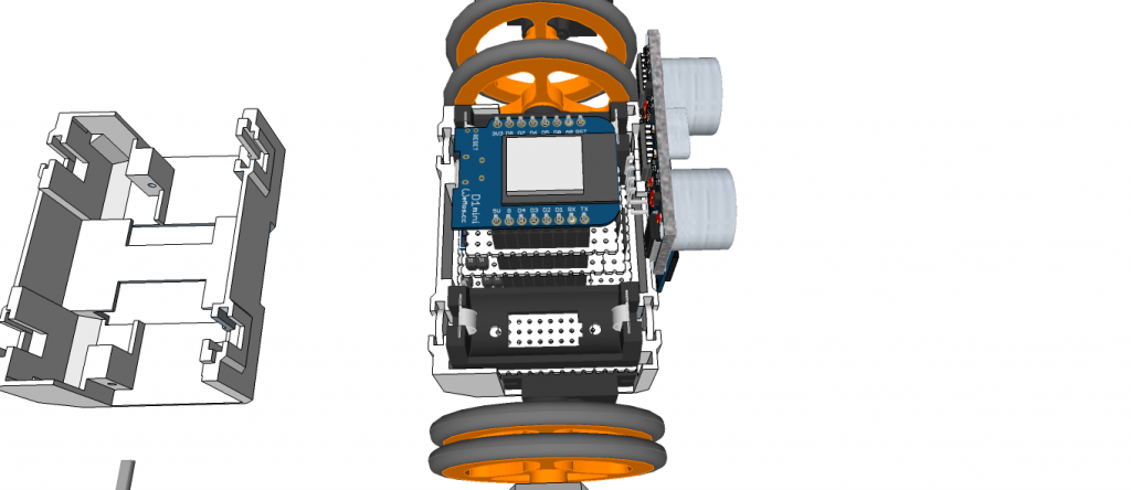
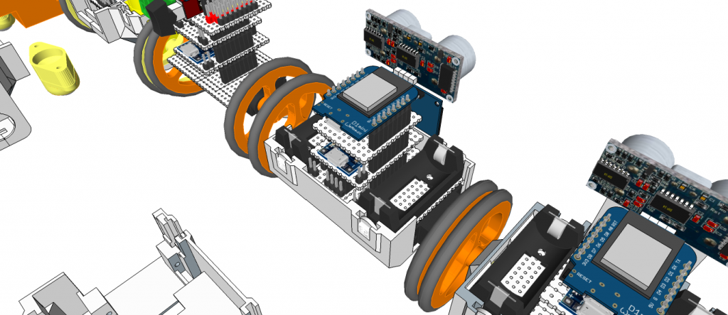
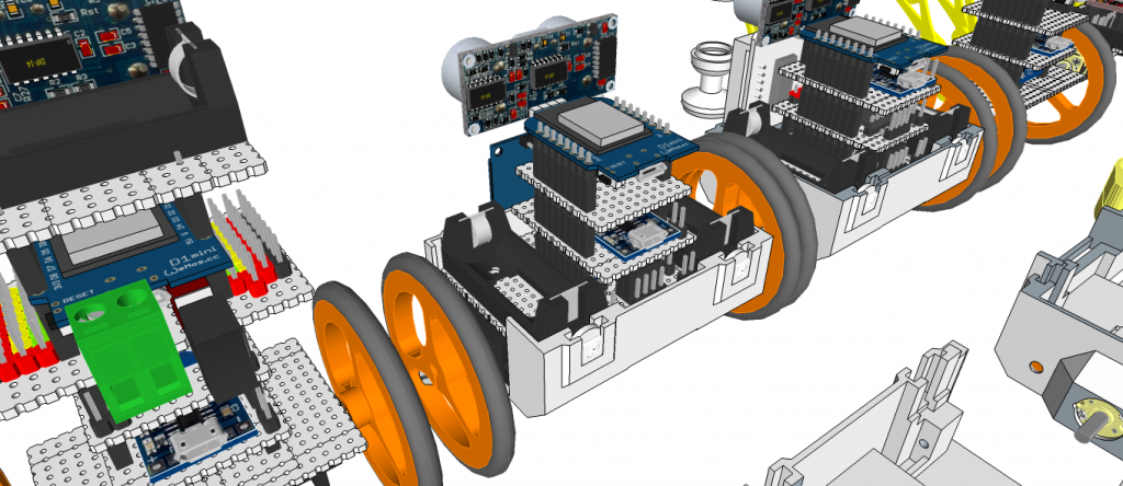
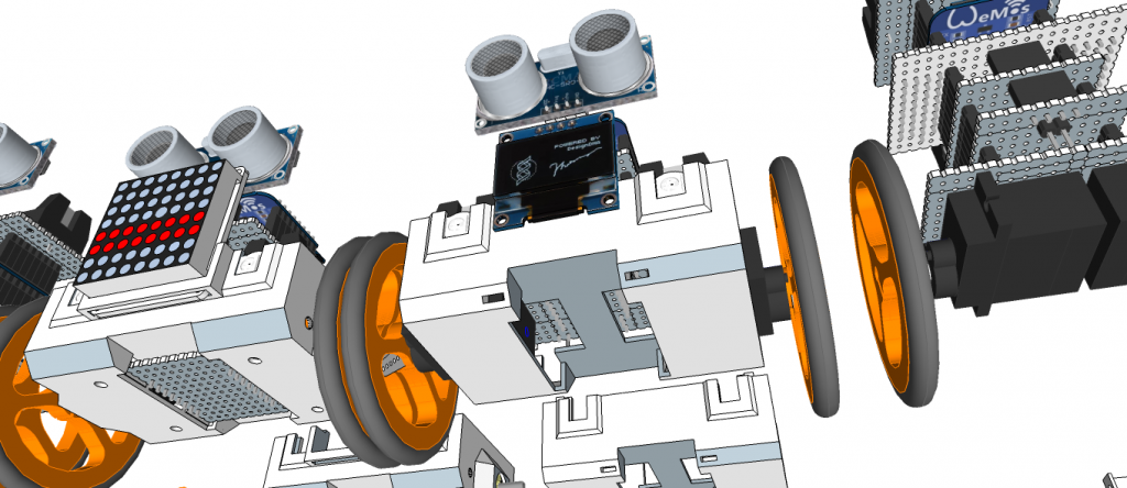
Robonoid is a Plen/mini-Plan/RoboHero robot derivative designed at Zalophus DesignHouse. We love the Plen2 robot but its want to new design. This is our take on a new lower cost version of the Plen2 robot using MG90S/ES08MA-II/SG90 servo’s.
The 3D printing parts were inspired by the Plen2 components, but they were redrawn from SketchUp to use the inexpensive MG90S servo motors.
Electronic Parts
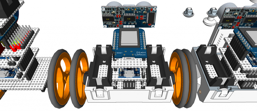
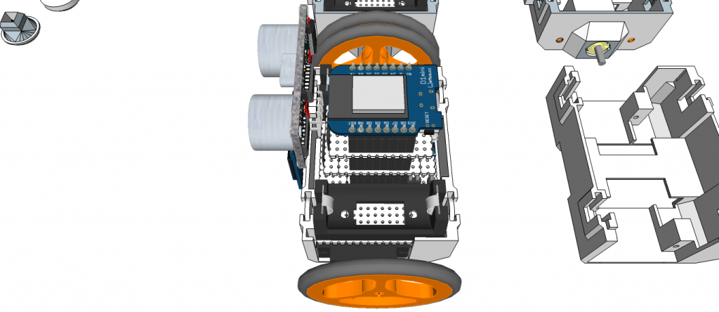
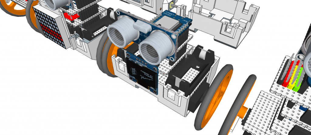
1 x WeMos D1 mini ESP8266 ESP-12
1 x PCA9685 16-channel, 12-bit PWM Fm+ I2C-bus Servo controller
1 x Shield Robonoid-20CH-R0a
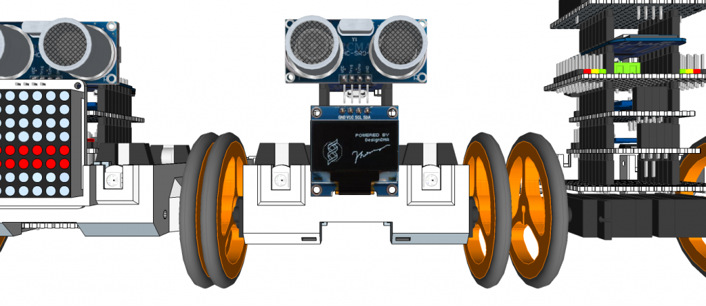
1 x HC-SR04 Ultrasonic Distance Measurement Sensor
2 x 16340 or 18650 Battery Holder
1 x 2S 7.4V Lithium Battery Charger Protection Board
2 x 16340 or 18650 Batteries
2 x Snap-In Single ‘A’-‘AA’ Battery Contacts 209 [KEYSTONE ELECTRONICS CORP.]
2 x Snap-In Single ‘A’-‘AA’ Battery Contacts 228 [KEYSTONE ELECTRONICS CORP.]
1 x DC Jack and Battery Harness Cable
17/19 x MG90S Metal Gear Servo Motors
The open source Humanoid Robot – Robonoid hardware and software is free and made with love. Please show your level of support with a voluntary donation.
Robonoid is small sized bipedal walking robot
The robot has 20 freely moveable joints and servomotor in order to provide for a range of action and stable movements. Since it’s small in size, Robonoid can balance well and cope with basic movements such as walking and getting up. Also, intricate movements like roller skating and skateboarding are possible.
Robonoid is a wireless controllable robot
You can control it by WiFi protocol through your PC and Smartphones. App for android and iOS are an especially intelligible UI. By using it, complicated operations can be controlled more easily.
Robonoid is a friendly robot
Robonoid was named indicates a “simply shaped robot” that everyone imagines. Robonoid was designed by pursuing a simple appearance and simple functionality.
Robonoid Lineup
– Papi – 28DOF
– S6 – 20DOF
– S4 – 14DOF
– PSY – 135.7mm(W) x 258.39mm(H) x 100mm(D) – 17DOF
– Jack – 135.7mm(W) x 305.62mm(H) x – 92,48mm(D) – 22DOF
– Gentleman – 135.7mm(W) x 341.22mm(H) x – 78.5mm(D) – 22DOF
– Tony – 135.7mm(W) x 265.5mm(H) x – 100mm(D) – 18DOF
– SpongwBob – 135.7mm(W) x 230.0mm(H) x 100mm(D) – 16DOF
– Hudi – 135.7mm(W) x 251.4mm(H) x 87mm(D) – 19DOF
– Gunmo – 135.7mm(W) x 259.3mm(H) x 78.5mm(D) – 19DOF
– Nova – 135.7mm(W) x 282.8mm(H) x 100mm(D) – 17DOF
– M1 – 180.7mm(W) x 350.74mm(H) x 110mm(D) – 24DOF
– Hexapod H1 – DOM 352.83mm(WD) x 193.16mm(H) – 20DOF
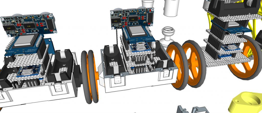
Robonoid is a Plen/mini-Plan/RoboHero robot derivative designed at Zalophus DesignHouse. We love the Plen2 robot but its want to new design. This is our take on a new lower cost version of the Plen2 robot using ES08MA-II/SG90 servo’s.
The 3D printing parts were inspired by the Plen2 components, but they were redrawn from SketchUp to use the inexpensive MG90S servo motors.
Electronic Parts
– 1 x WeMos D1 mini ESP8266 ESP-12
– 1 x PCA9685 16-channel, 12-bit PWM Fm+ I2C-bus Servo controller
– 1 x Robonoid-20CH-R0a Shield
– 1 x HC-SR04 Ultrasonic Distance Measurement Sensor
– 2 x 16340 Battery Holder
– 1 x 2S 7.4V Lithium Battery Charger Protection Board
– 2 x 16340 Batteries
– 1 x DC Jack and Battery Harness Cable
– 20 x ES08MA-II Metal Gear Servo Motors
The open source Humanoid Robot – Robonoid hardware and software is free and made with love. Please show your level of support with a voluntary donation.
Robonoid is small sized bipedal walking robot The robot has 17 or 19, 24 freely moveable joints and servomotor in order to provide for a range of action and stable movements. Since it’s small in size, Robonoid can balance well and cope with basic movements such as walking and getting up. Also, intricate movements like roller skating and skateboarding are possible.
Robonoid is a wireless controllable robot You can control it by WiFi protocol through your PC and Smartphones. App for android and iOS are an especially intelligible UI. By using it, complicated operations can be controlled more easily.
Robonoid is a friendly robot Robonoid was named indicates a “simply shaped robot” that everyone imagines. Robonoid was designed by pursuing a simple appearance and simple functionality.
PSY – 135.7mm(W) x 258.39mm(H) x 100mm(D) – 17DOF
Jack – 135.7mm(W) x 305.62mm(H) x – 92,48mm(D) – 22DOF
Gentleman – 135.7mm(W) x 341.22mm(H) x – 78.5mm(D) – 22DOF
Tony – 135.7mm(W) x 265.5mm(H) x – 100mm(D) – 18DOF
SpongwBob – 135.7mm(W) x 230.0mm(H) x 100mm(D) – 16DOF
Hudi – 135.7mm(W) x 251.4mm(H) x 87mm(D) – 19DOF
Gunmo – 135.7mm(W) x 259.3mm(H) x 78.5mm(D) – 19DOF – https://youtu.be/qIZJZDcRpVw
Nova – 135.7mm(W) x 282.8mm(H) x 100mm(D) – 17DOF – https://youtu.be/kzfyKRzp_9I
Hexapod S1 – DOM 352.83mm(WD) x 193.16mm(H) – 20DOF
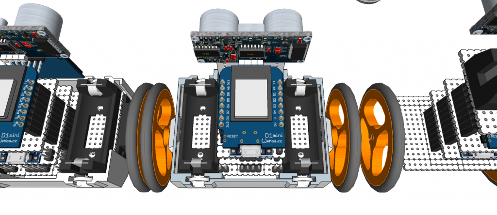
Robonoid is a Plen/mini-Plan/RoboHero robot derivative designed at Zalophus DesignHouse. We love the Plen2 robot but its want to new design. This is our take on a new lower cost version of the Plen2 robot using MG90S/ES08MA-II/SG90 servo’s.
The 3D printing parts were inspired by the Plen2 components, but they were redrawn from SketchUp to use the inexpensive MG90S servo motors.
Electronic Parts
1 x WeMos D1 mini ESP8266 ESP-12
1 x PCA9685 16-channel, 12-bit PWM Fm+ I2C-bus Servo controller
1 x Shield Robonoid-20CH-R0a
1 x HC-SR04 Ultrasonic Distance Measurement Sensor
2 x 16340 or 18650 Battery Holder
1 x 2S 7.4V Lithium Battery Charger Protection Board
2 x 16340 or 18650 Batteries
2 x Snap-In Single ‘A’-‘AA’ Battery Contacts 209 [KEYSTONE ELECTRONICS CORP.]
2 x Snap-In Single ‘A’-‘AA’ Battery Contacts 228 [KEYSTONE ELECTRONICS CORP.]
1 x DC Jack and Battery Harness Cable
17/19 x MG90S Metal Gear Servo Motors
The open source Humanoid Robot – Robonoid hardware and software is free and made with love. Please show your level of support with a voluntary donation.
The following instructions relate to installation on the standard Raspberry Pi Operating System (OS) Raspbian. Following the principals shown here, it should be possible to apply these same modifications to other Raspberry OS’s.
The Arduino processor on the Sleepy Pi can be programmed directly from the Arduino IDE running on the Raspberry Pi.
The first step is to load the Arduino environment onto the Raspberry Pi. If you haven’t already done so, it’s a good idea to ensure that your Raspbian is up to date by opening up an LXTerminal window and executing the following:
1
2
$sudo apt–get update
$sudo apt–get dist–upgrade
Note the dist-upgrade will ensure that you have the latest versions of RPi.GPIO which will be required later.
Now install the Arduino IDE with:
1
$sudo apt–get install arduino
(click Y to any dependencies)
Setting up the Serial Pins
The Arduino processor on the Sleepy Pi can be programmed directly from the Raspberry Pi using the serial GPIO lines on the RPi and another GPIO line to reset the the Arduino to allow automatic code upload. These pins are:
GPIO 14: TXD
GPIO 15: RXD
GPIO 22: Reset (see next section)
By default Raspbian has exclusive access to the serial pins to output status, debug data and logging in. We need to change that using the following steps.
Step 1: Disable Serial login
Wheezy
Raspbian allows you to login using the serial port. To use the Sleepy Pi we need to disable this. To do this, we need to edit /etc/inittab.
In an LXTerminal window type:
1
$sudo nano/etc/inittab
Scroll down the bottom and you will find the lines:
1
2
#Spawn a getty on Raspberry Pi Serial line
T0:23:respawn:/sbin/getty–LttyAMA0115200vt100
You need to comment the last line out (i.e. disabling it) with a “#” and save it, so that it results in:
Raspbian Jessie no longer has the /etc/inittab file and replaces it instead with a mechanism called systemd and you use a tool called systemctl to enable / disable services.
In a terminal type the following commands, for all Raspberry Pi’s except Raspberry Pi 3:
On Jessie, you also need to enable the serial port in either rasp-config of in /boot/config.txt with:
1
$sudo nano/boot/config.txt
and add the line:
1
enable_uart=1
Step 2. Disable Boot info
When Raspbian boots up it outputs boot information to the serial port and hence streams it to the Sleepy Pi (which is not particularly interested in it). To disable this we need to edit the /boot/cmdline.txt in LXTerminal:
NOTE: For Raspberry Pi 3 Omit Step 3 – /dev/ttyS0 is the default mapping not /dev/ttyAMA0 which is used for the Bluetooth.
The Arduino IDE wants to use the /dev/ttyS0 serial port, but we need to use the /dev/ttyAMA0 which is linked to the GPIO. In order to do this we need to create a permanent link that maps AMA0 to S0. To this we need to create a small file. We can do this in LXTerminal by the following sequence:
1
$sudo nano
In the new file that it creates type the following:
The Sleepy Pi Arduino processor reset line in connected to GPIO 22. To automatically upload code from the Arduino IDE we need to pulse this line low to rest the Arduino and enter bootload mode.
On a normal Arduino system connected to a computer via a USB / serial cable the reset line is connected to the DTR line. To replicate this behavior on the Raspberry Pi we need to hack the AVRDude programming software. Dean Mao has detailed a great hack for this. He’s produced a modified version of Avrdude (avrdude-autoreset) and written a piece of python code (autoreset) that runs in the background and pulses the GPIO line when required.
Download the avrdude-rpi files from Github . Select “Download ZIP” file which will download the file into your /home/pidirectory.
NOTE: this is a subtly modified version of the original Dean Mao version so only use this version.
Open up a File Manager window from the bottom toolbar, locate the ZIP file in your /home/Pi directory and right-click and select xarchiver to extract the files to a folder in /home/Pi. These will extract into a folder named “avrdude-rpi-master“.
If you are using a terminal rather than the GUI, you can use the following from the command lines to download and unzip :
Then link the new avrdude-autoreset to avrdude with the ‘ln” command so that when something calls for avrdude, the new version runs instead.
Adding the Sleepy Pi to the Arduino environment
To enable the Sleepy Pi to be selected from the IDE you need to add a folder and file to your sketchbook. If it is a fresh install and you haven’t yet run the Arduino environment you’ll need to create a sketchbook folder (skip this step if it already exists).
In LXTerminal type:
1
2
3
$mkdir/home/pi/sketchbook
$mkdir/home/pi/sketchbook/hardware
$mkdir/home/pi/sketchbook/hardware/Sleepy_pi
to create folders “hardware” and “sleepy pi” in your Arduino sketchbook.
Download and copy the boards.txt file to the Sleepy Pi folder.


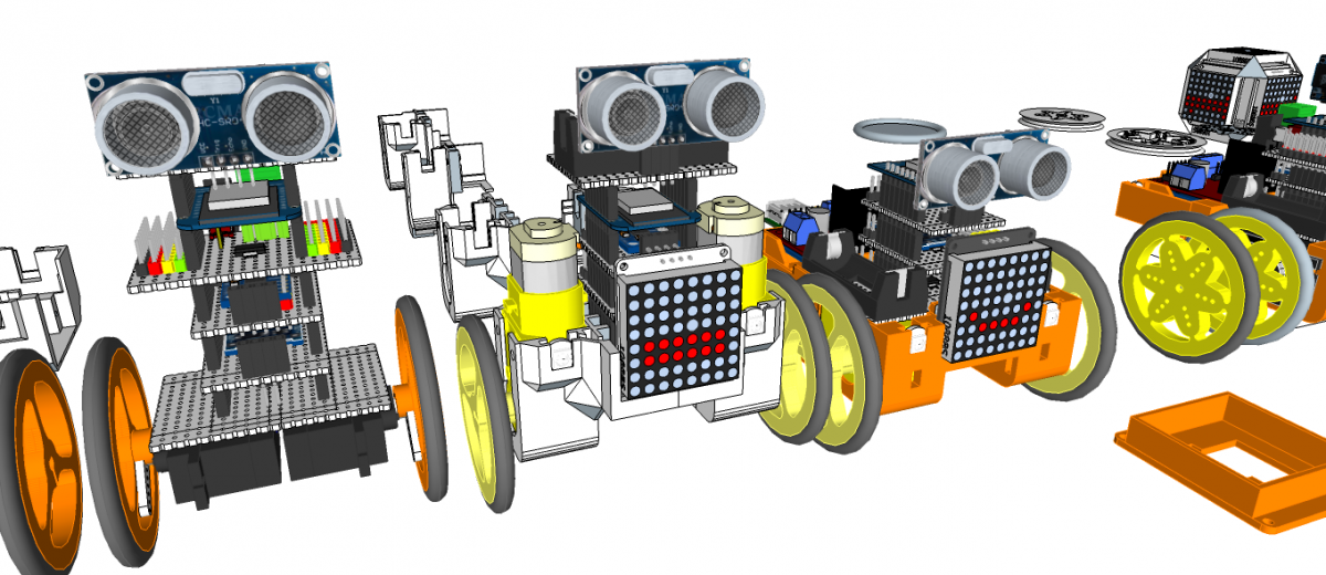
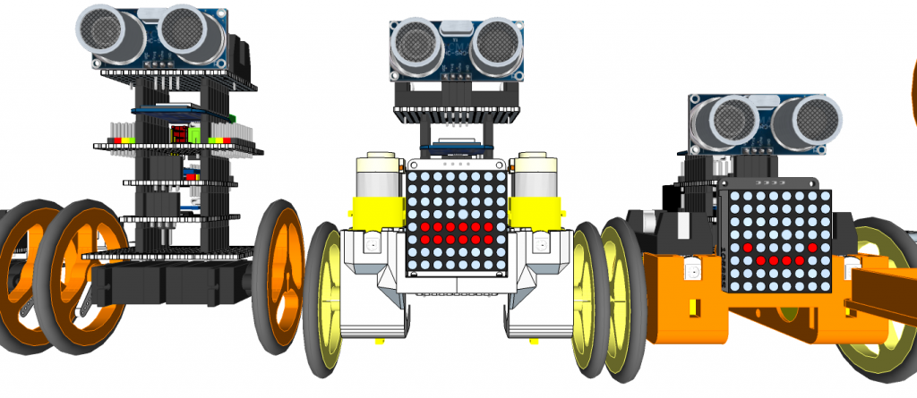
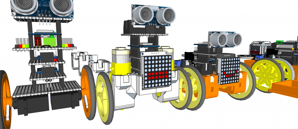
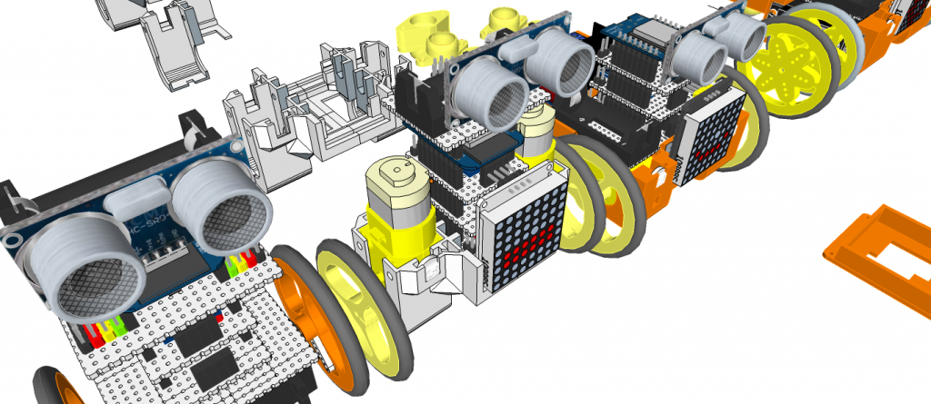
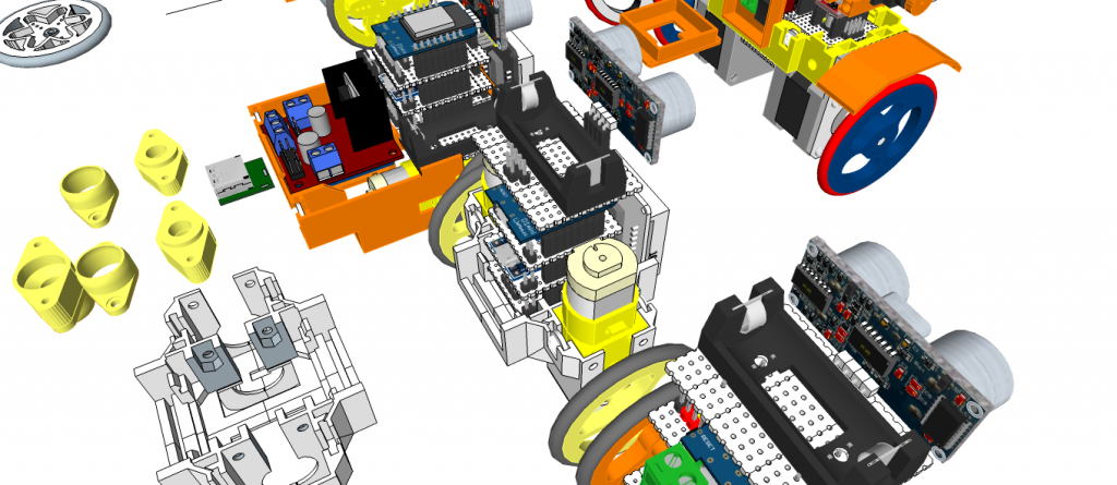
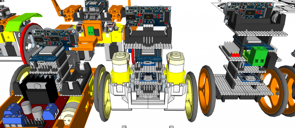
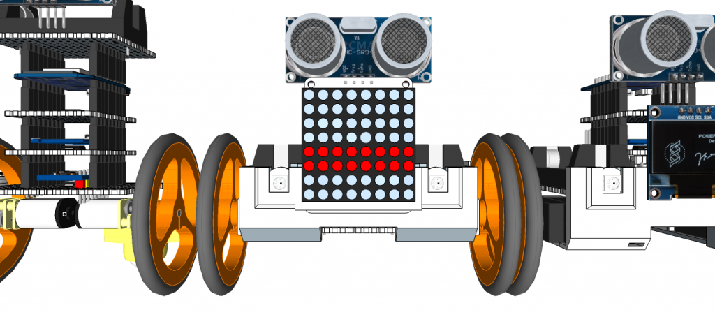
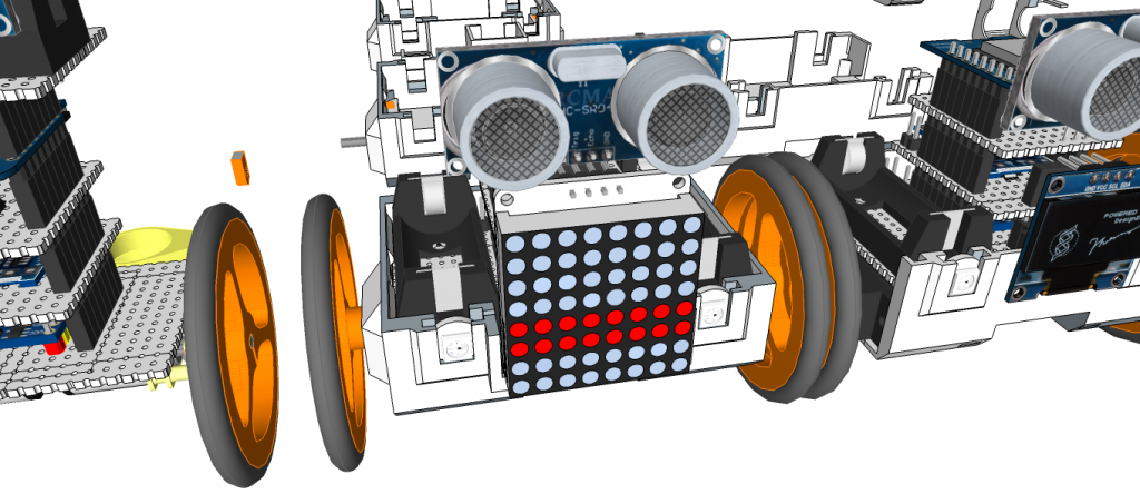
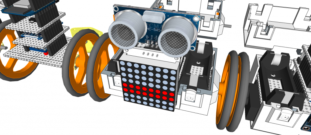
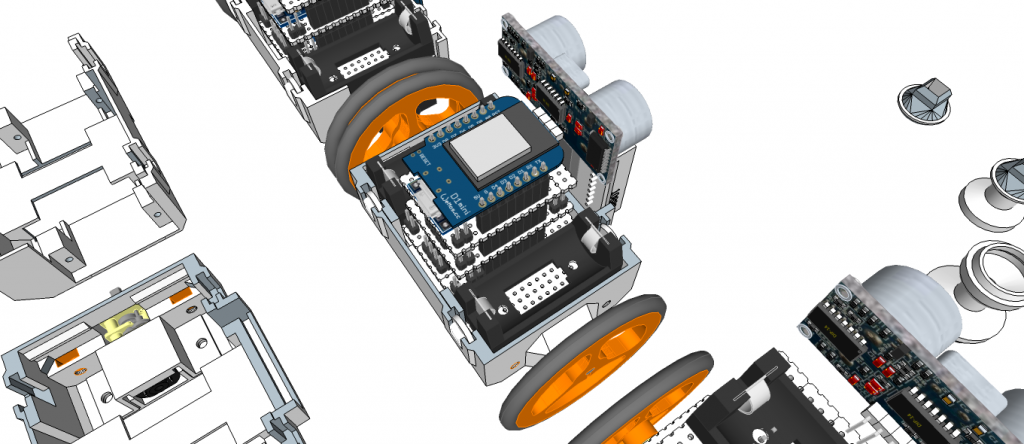
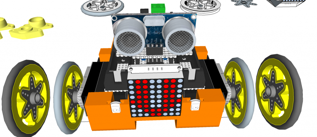
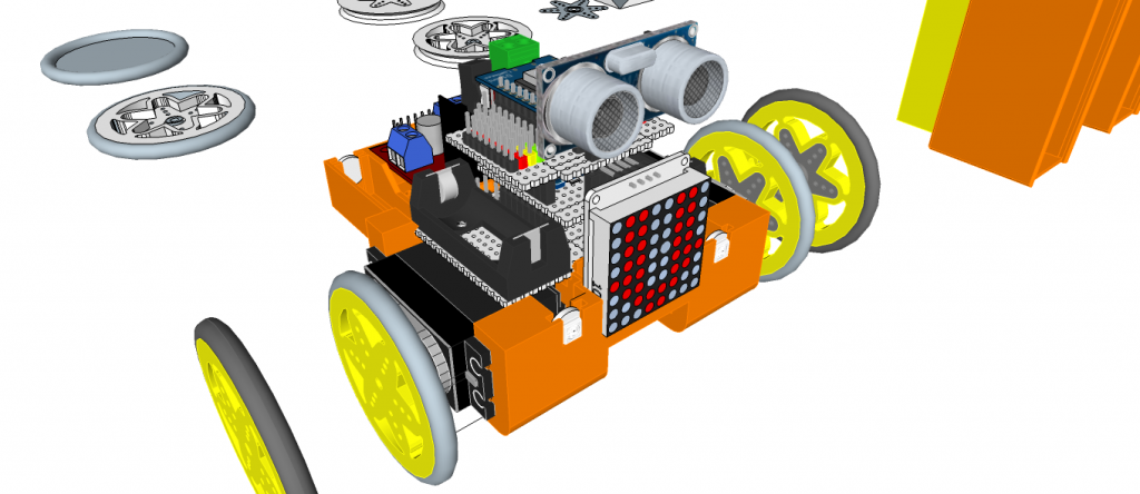
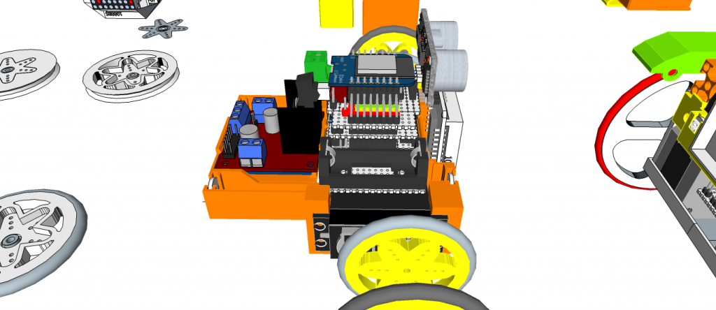
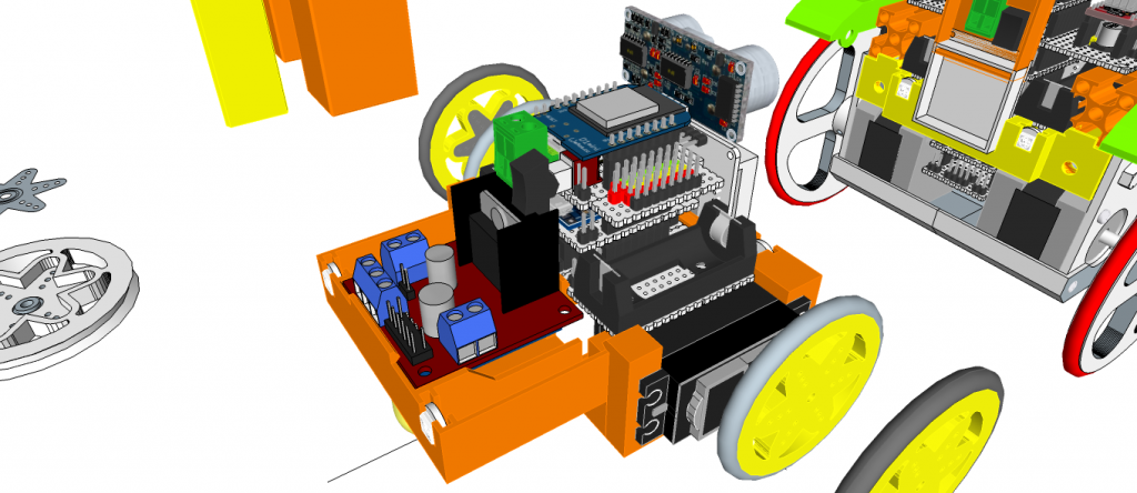
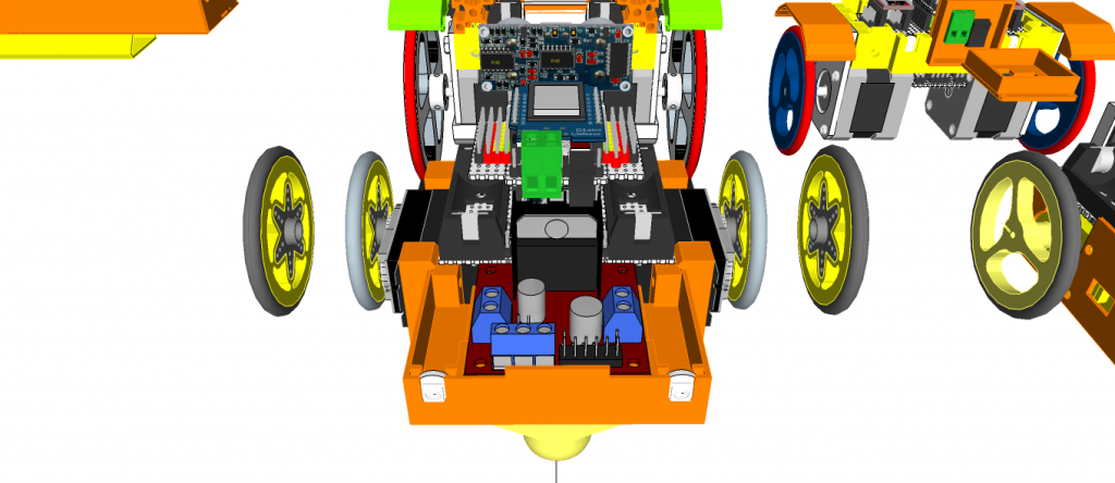
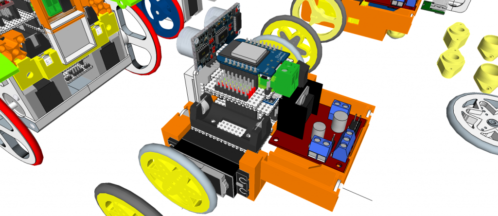
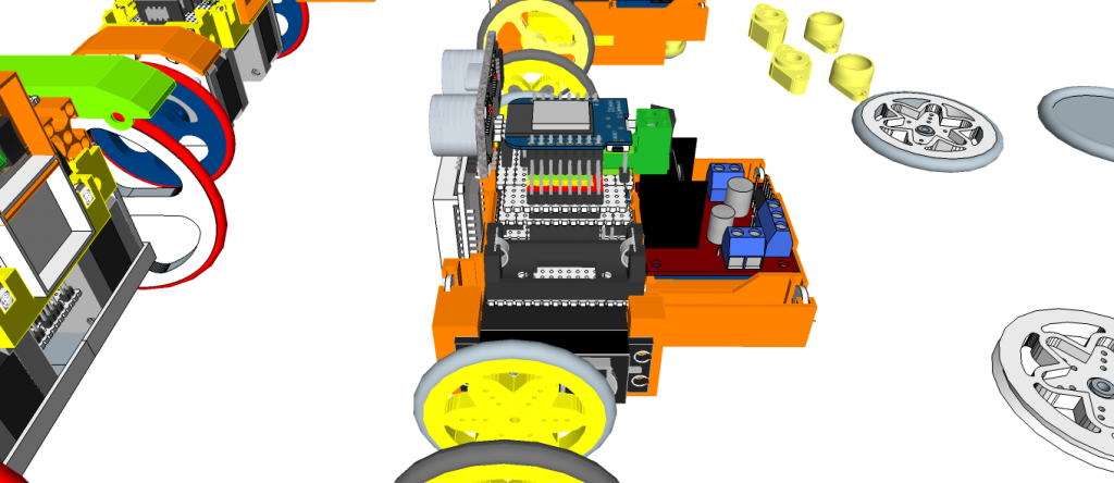
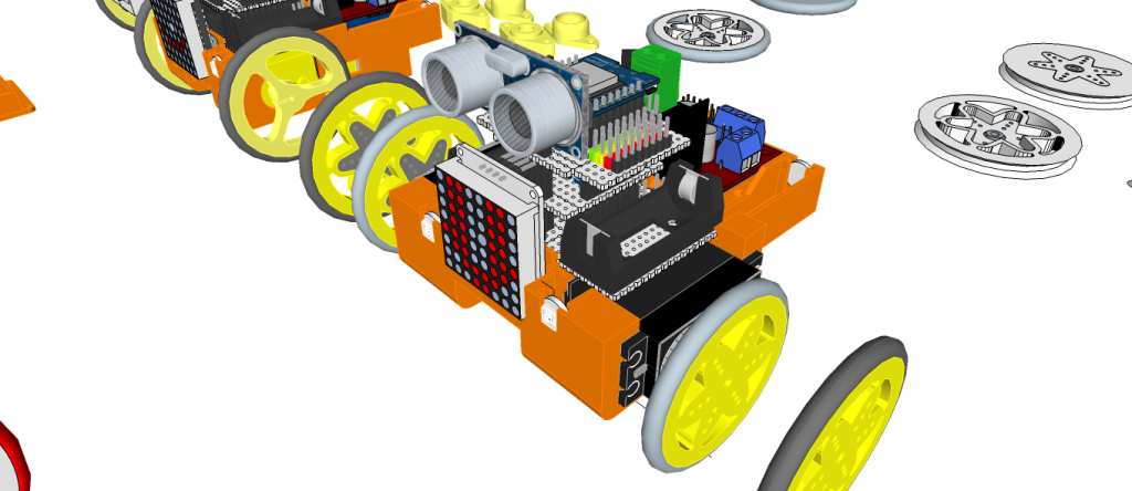
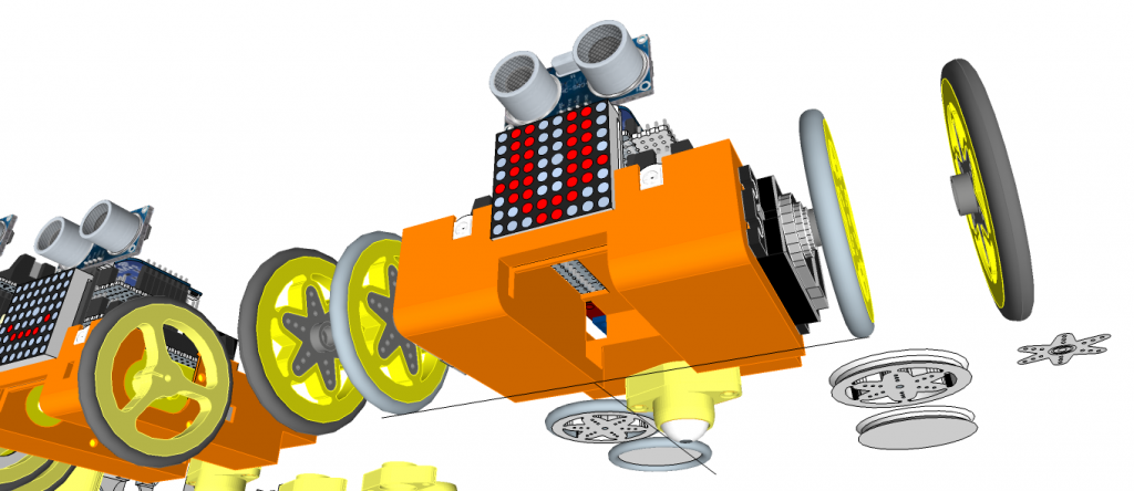
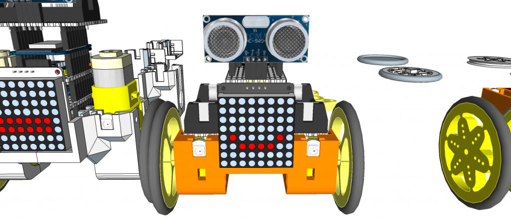
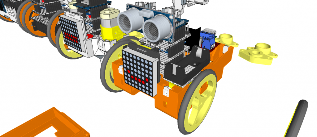
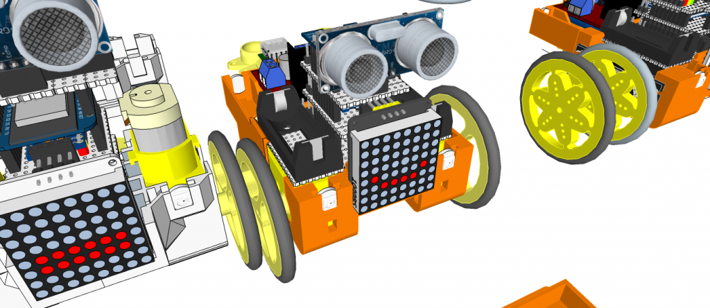
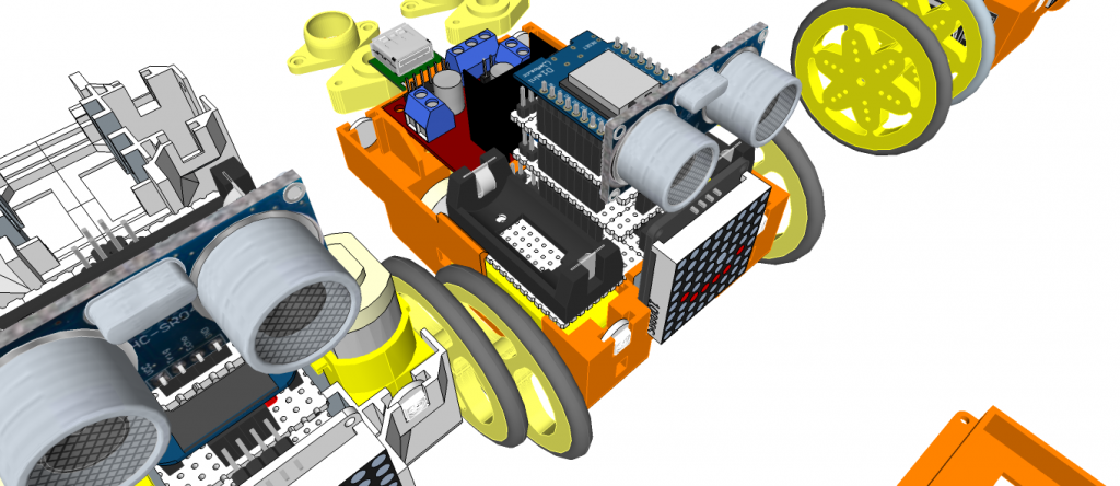
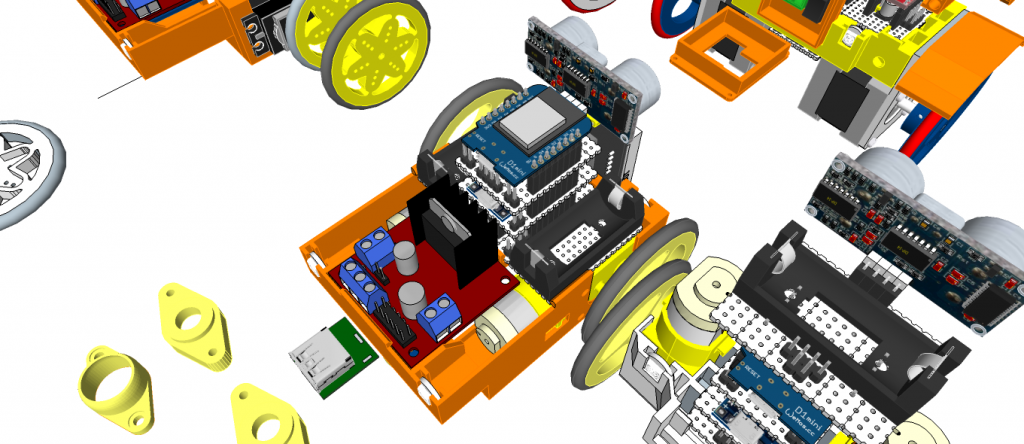
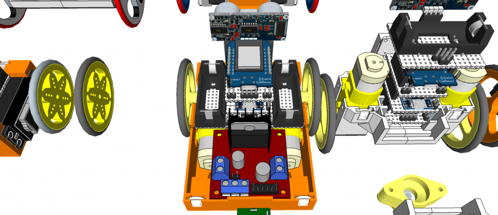
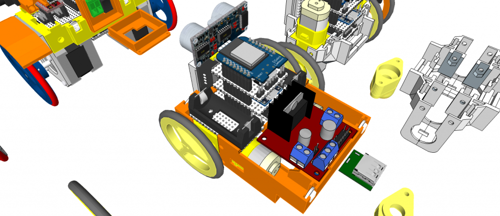
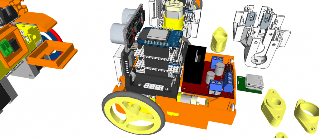
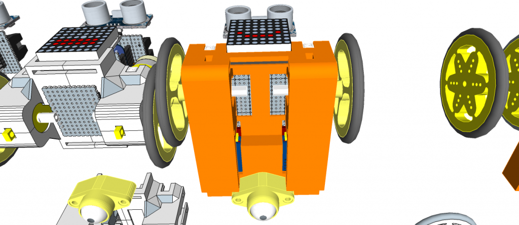
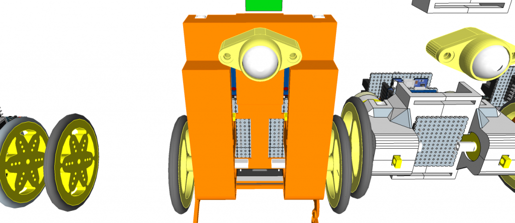
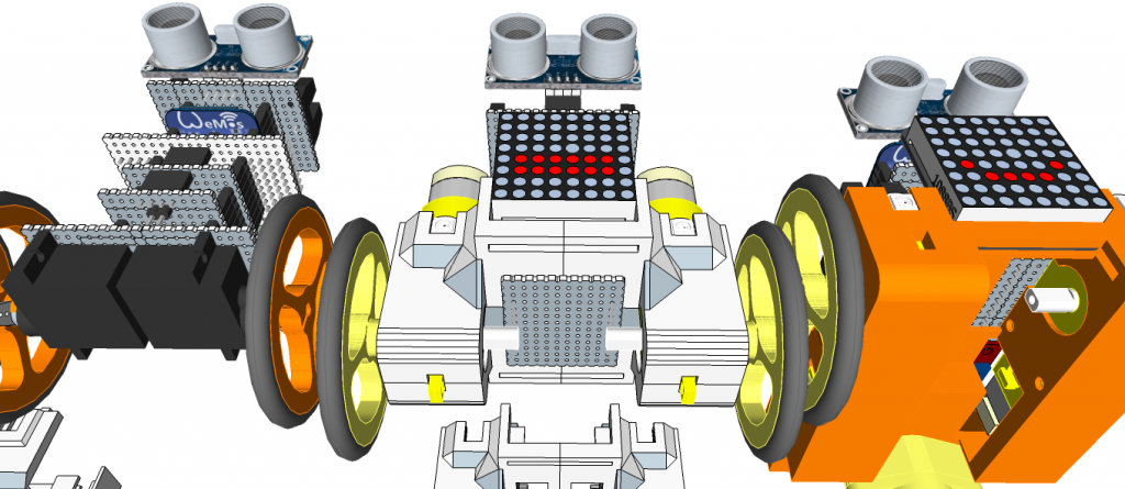 miniMe-BB: N20 motor type