
Tag: Remote Control
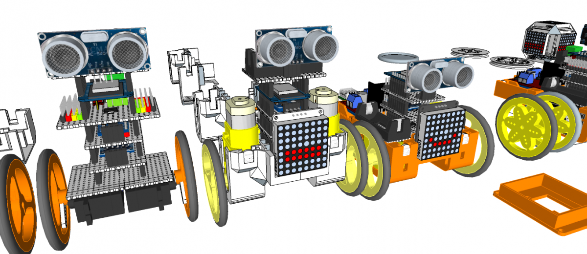
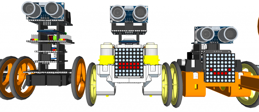
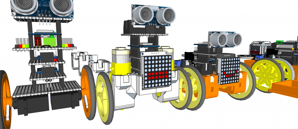
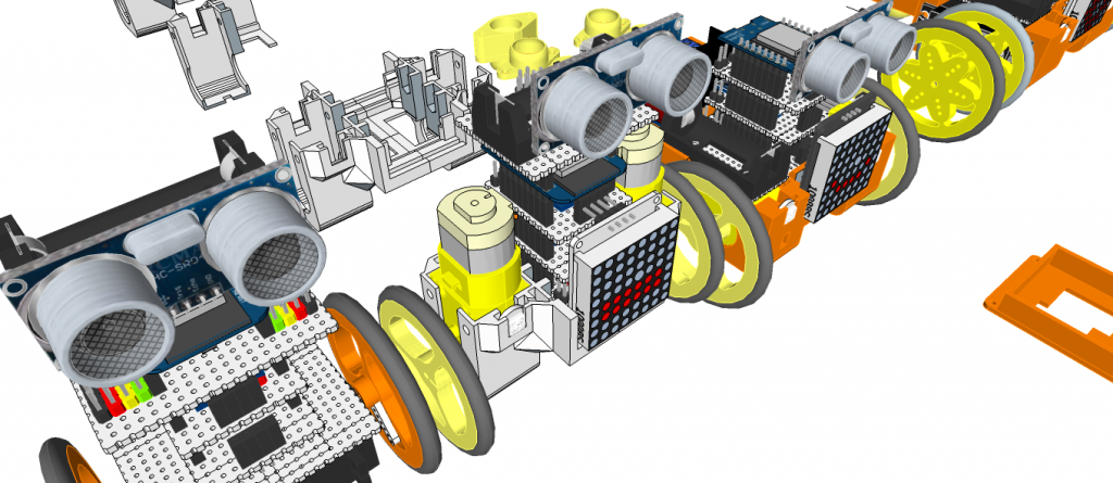
3D Printed Humanoid Robot – Robonoid – LineUp – 20180621
[20190107] Upload Links
[20181101] Printing
[20180621] Update Design concept
[20180619] Update Design concept
[20180607] Update Design concept
[20180604] Update Design concept
[20180430] Design concept
Humanoid Robot – Robonoid – Design concept – https://youtu.be/n-flpiyNw-M
3D Design Tool: SketchUp Pro
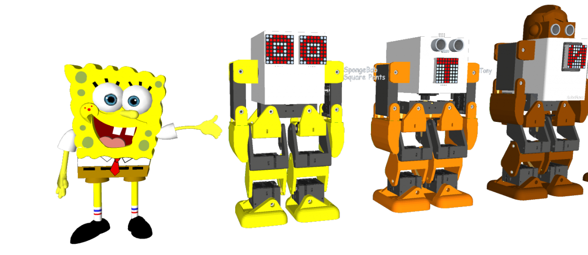
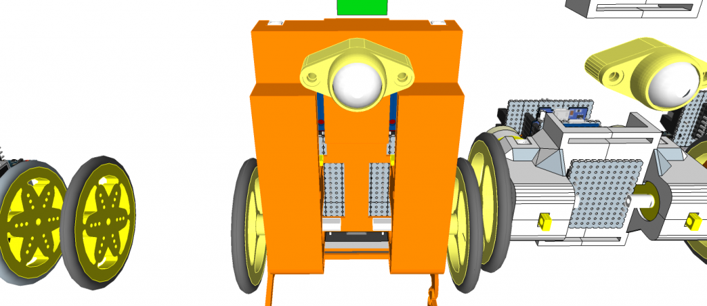
Robonoid is small sized bipedal walking robot The robot has 17 or 19, 24 freely moveable joints and servomotor in order to provide for a range of action and stable movements. Since it’s small in size, Robonoid can balance well and cope with basic movements such as walking and getting up. Also, intricate movements like roller skating and skateboarding are possible.
Robonoid is a wireless controllable robot You can control it by WiFi protocol through your PC and Smartphones. App for android and iOS are an especially intelligible UI. By using it, complicated operations can be controlled more easily.
Robonoid is a friendly robot Robonoid was named indicates a “simply shaped robot” that everyone imagines. Robonoid was designed by pursuing a simple appearance and simple functionality.
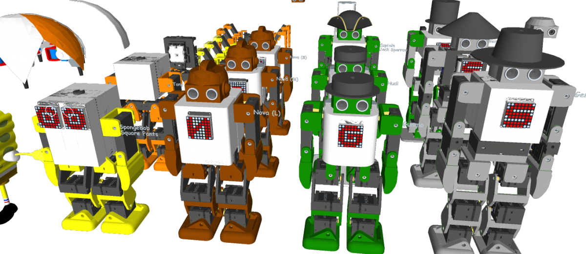
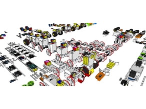
Robonoid Lineup
PSY – 135.7mm(W) x 258.39mm(H) x 100mm(D) – 17DOF
Jack – 135.7mm(W) x 305.62mm(H) x – 92,48mm(D) – 22DOF
Gentleman – 135.7mm(W) x 341.22mm(H) x – 78.5mm(D) – 22DOF
Tony – 135.7mm(W) x 265.5mm(H) x – 100mm(D) – 18DOF
SpongwBob – 135.7mm(W) x 230.0mm(H) x 100mm(D) – 16DOF
Hudi – 135.7mm(W) x 251.4mm(H) x 87mm(D) – 19DOF
Gunmo – 135.7mm(W) x 259.3mm(H) x 78.5mm(D) – 19DOF – https://youtu.be/qIZJZDcRpVw
Nova – 135.7mm(W) x 282.8mm(H) x 100mm(D) – 17DOF – https://youtu.be/kzfyKRzp_9I
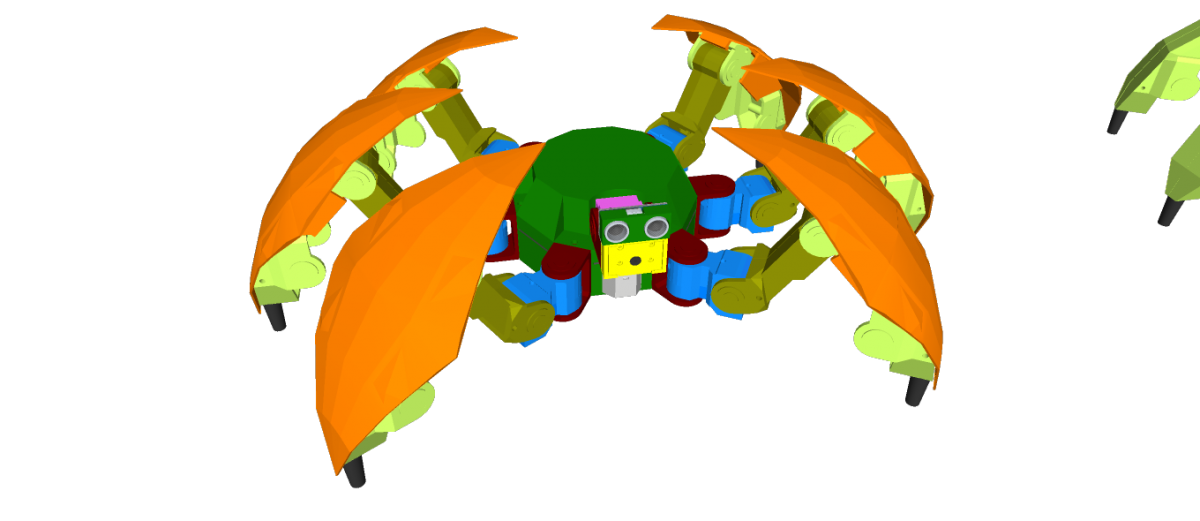
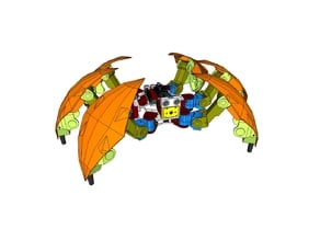
Hexapod S1 – DOM 352.83mm(WD) x 193.16mm(H) – 20DOF
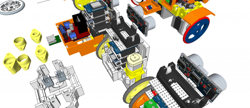
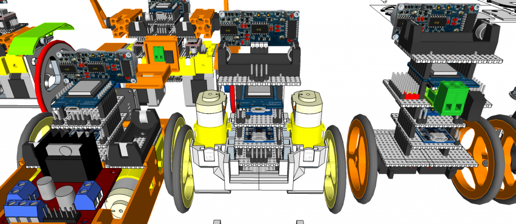
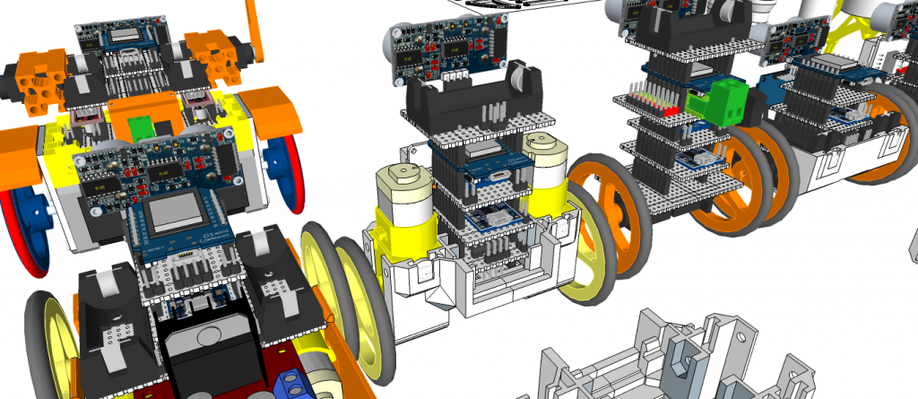
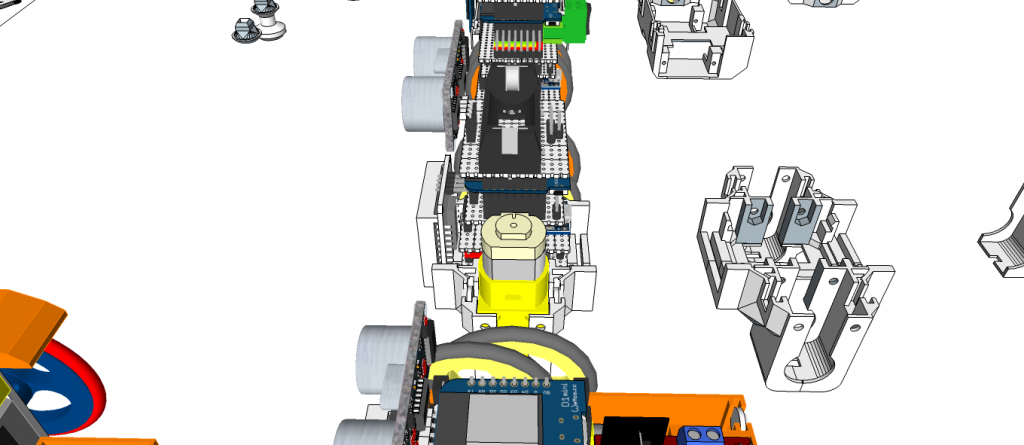
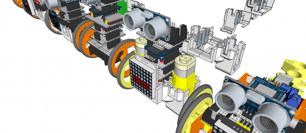
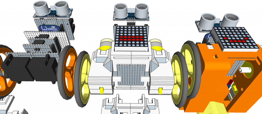
Robonoid is a Plen/mini-Plan/RoboHero robot derivative designed at Zalophus DesignHouse. We love the Plen2 robot but its want to new design. This is our take on a new lower cost version of the Plen2 robot using MG90S/ES08MA-II/SG90 servo’s.
The 3D printing parts were inspired by the Plen2 components, but they were redrawn from SketchUp to use the inexpensive MG90S servo motors.
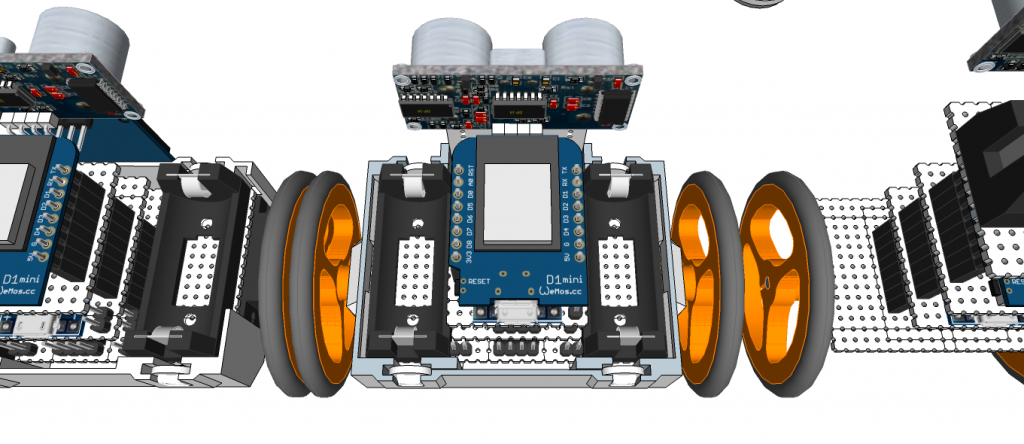
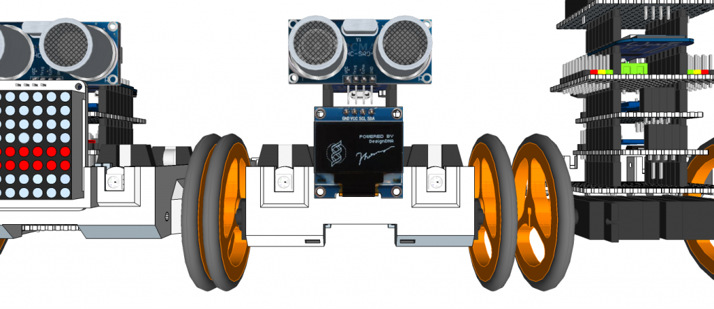
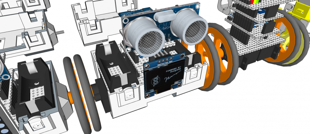
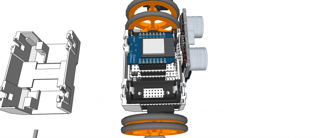
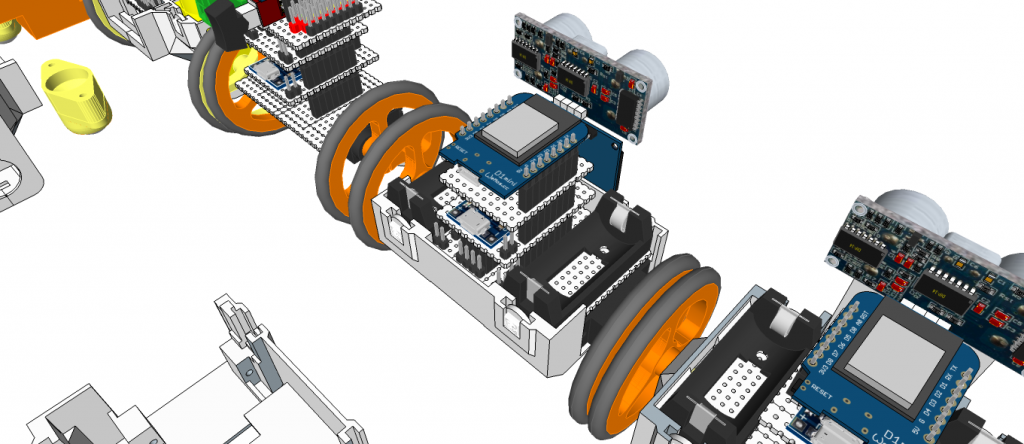
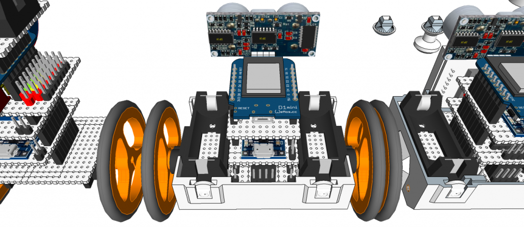
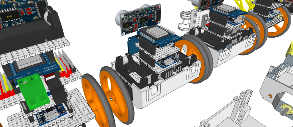
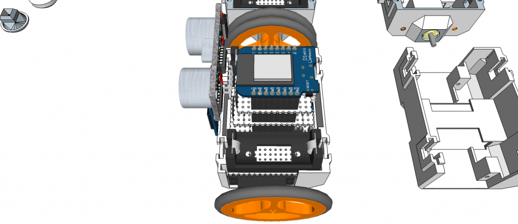
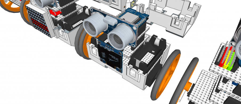
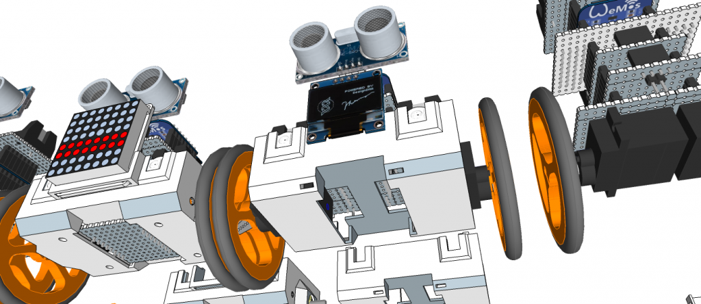
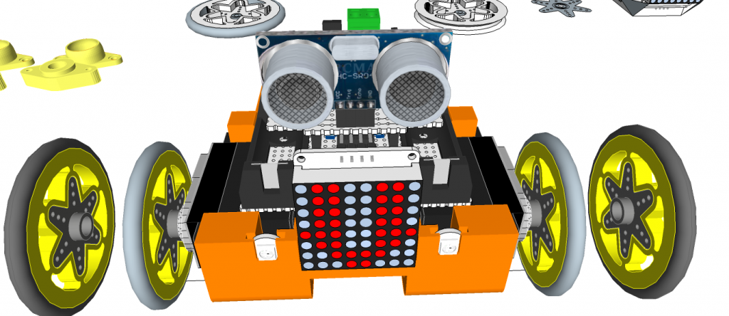
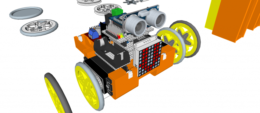
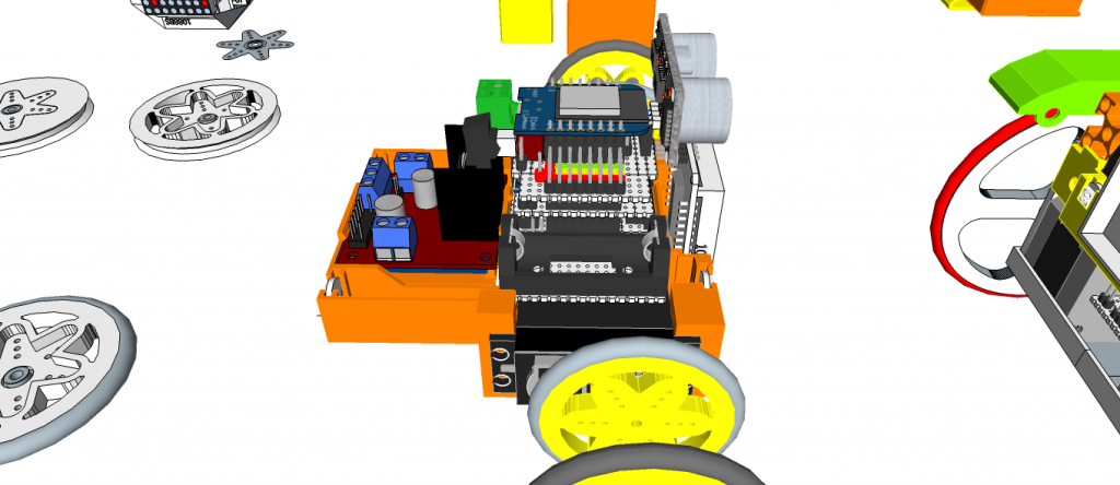
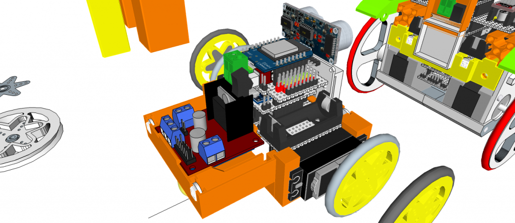
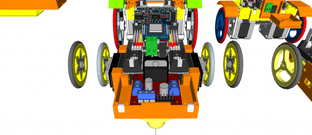
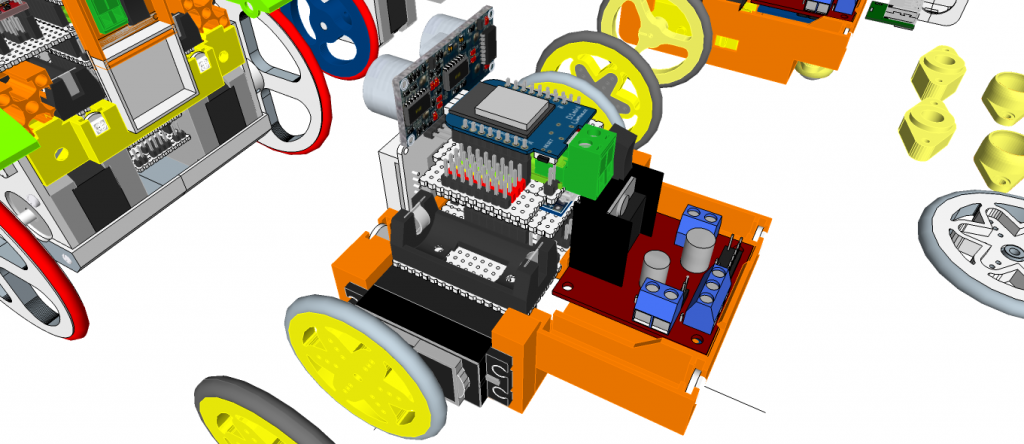
Electronic Parts
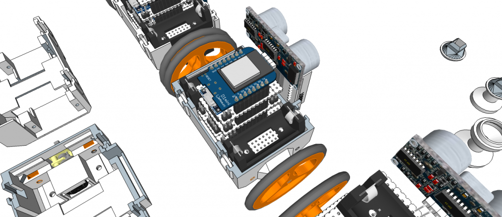
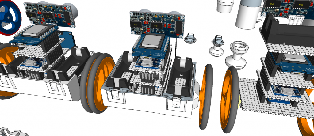
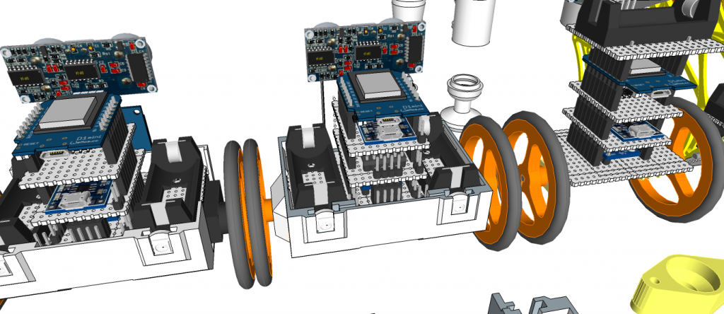
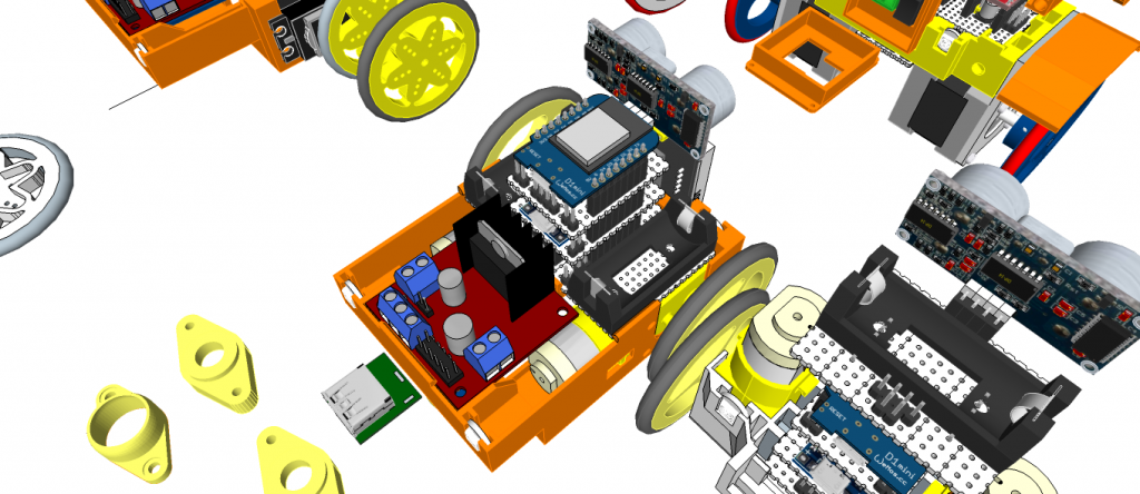
1 x WeMos D1 mini ESP8266 ESP-12
1 x PCA9685 16-channel, 12-bit PWM Fm+ I2C-bus Servo controller
1 x Shield Robonoid-20CH-R0a
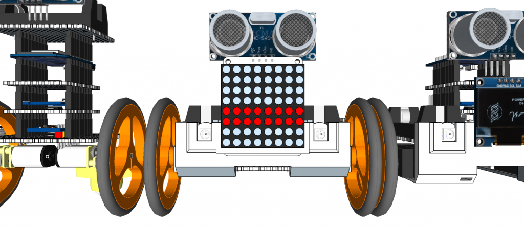
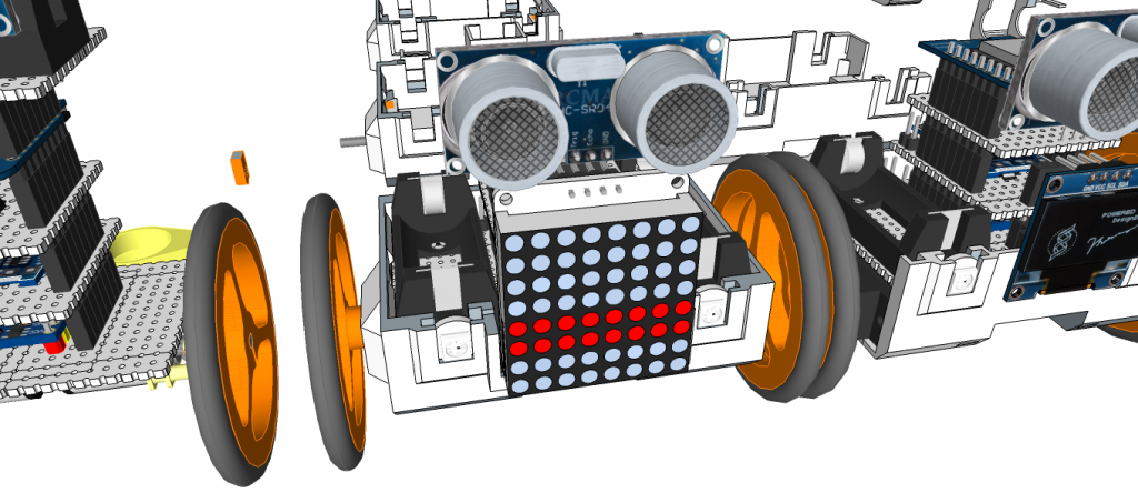
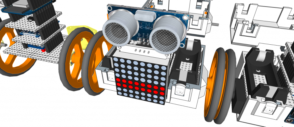
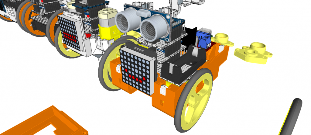
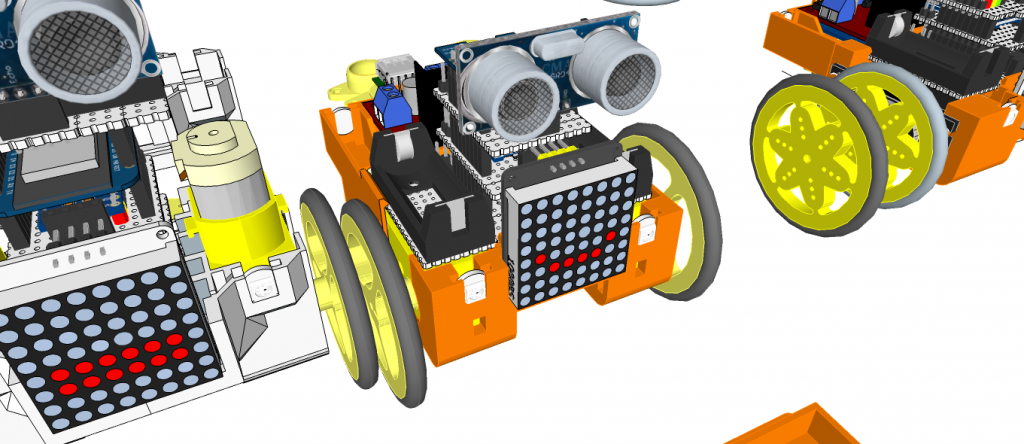
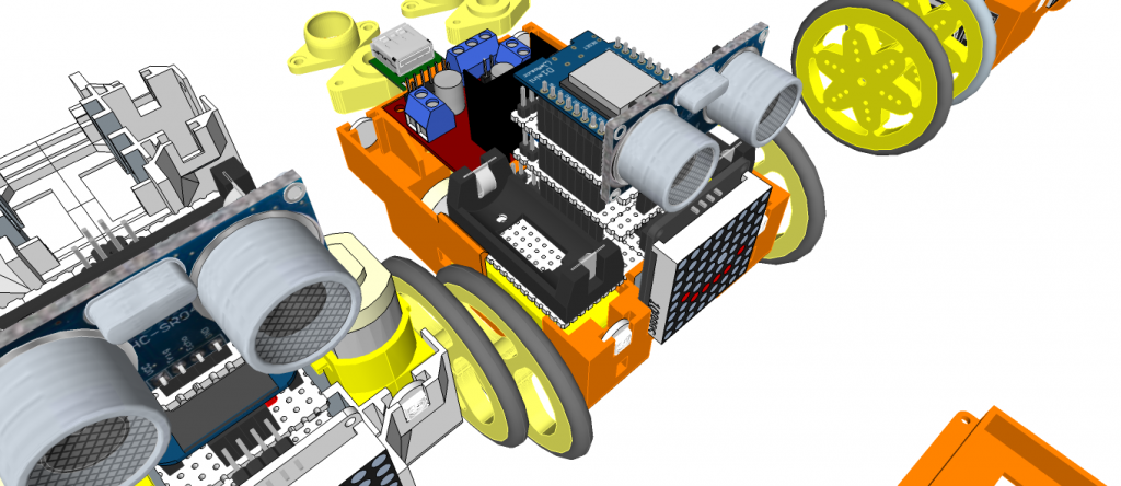
1 x HC-SR04 Ultrasonic Distance Measurement Sensor
2 x 16340 or 18650 Battery Holder
1 x 2S 7.4V Lithium Battery Charger Protection Board
2 x 16340 or 18650 Batteries
2 x Snap-In Single ‘A’-‘AA’ Battery Contacts 209 [KEYSTONE ELECTRONICS CORP.]
2 x Snap-In Single ‘A’-‘AA’ Battery Contacts 228 [KEYSTONE ELECTRONICS CORP.]
1 x DC Jack and Battery Harness Cable
17/19 x MG90S Metal Gear Servo Motors
3D Printing Parts
- Robonoid_BatteryBracket16340.stl ……https://pinshape.com/items/49080
- Robonoid_BatteryHolder18650.stl …..https://pinshape.com/items/49082
- Robonoid_BodyGentleman.stl ……..https://pinshape.com/items/49105
- Robonoid_BodyGunmo.stl …….https://pinshape.com/items/49100
- Robonoid_BodyHudi.stl ……https://pinshape.com/items/49098
- Robonoid_BodyNovaL.stl …….https://pinshape.com/items/49101
- Robonoid_BodySpongeBob.stl ……………”
- Robonoid_BodyNovaS.stl …..https://pinshape.com/items/49103
- Robonoid_BodyTony.stl …….https://pinshape.com/items/49102
- Robonoid_BodyTonyPants.stl ……”
- Robonoid_BodyTonyServoBracket.stl ……”
Robonoid_CapBaseball.stl ……https://pinshape.com/items/49095 - Robonoid_CapHudi.stl ………………..”
Robonoid_eYeLED5.stl ……….https://pinshape.com/items/49106
Robonoid_eYeWS2812.stl …….https://pinshape.com/items/49107
Robonoid_HatBoaterGunmo.stl ……https://pinshape.com/items/49093 - Robonoid_HatConical.stl ……………….”
- Robonoid_HatFes.stl ……………………..”
- Robonoid_HatTC.stl ……………………..”
- Robonoid_HatTop.stl …………………….”
Robonoid_Head.stl ……https://pinshape.com/items/49091
Robonoid_HeadNova.stl …….https://pinshape.com/items/49000
Robonoid_ElbowShoulderRol_Leftl.stl …….https://pinshape.com/items/49071
Robonoid_Foot_Left.stl …….https://pinshape.com/items/49057
Robonoid_FootSlim_Left.stl …….https://pinshape.com/items/49057
Robonoid_FootSimple_Left.stl ……..https://pinshape.com/items/49057
Robonoid_FootRollPitch_Left.stl …….https://pinshape.com/items/49063
Robonoid_Hand_Left.stl ……..https://pinshape.com/items/49070
Robonoid_HandWristShoulderPitchThighYawFoot_Left.stl ….https://pinshape.com/items/49072
Robonoid_Knee_Left.stl ……https://pinshape.com/items/49064
Robonoid_KneePitch_Left.stl ……..https://pinshape.com/items/49067
Robonoid_ShoulderPitch_Left.stl ……..https://pinshape.com/items/49072
Robonoid_ThighPitchHipRollNova_Left.stl ……..https://pinshape.com/items/49068
Robonoid_ThighPitchRoll_Left.stl ……https://pinshape.com/items/49063
Robonoid_Pants.stl …….https://pinshape.com/items/49105
Robonoid_PantsBottom.stl ……………”
WANT TO SUPPORT Zalophus’s DesignHouse?
The open source Humanoid Robot – Robonoid hardware and software is free and made with love. Please show your level of support with a voluntary donation.
Donate: https://www.paypal.com/cgi-bin/webscr?cmd=_s-xclick&hosted_button_id=RDN7ZGAVFS5UE
3D Printed Hexapod Robot – Robonoid – H1 – Design concept – Update – 20180621
___
Hexapod Robot – Robonoid – H1 -Design concept
___
Update design concept 20180621]
– Parts Update: pinshape: https://pinshape.com/items/26844
Update design concept 20170418]
– Parts Upload: pinshape: https://pinshape.com/items/26844
[ Upload design concept 20161001]
___
3D Printer: PANDORA DXs – DIY Desktop 3D Printer
3D Design Tool: SketchUp Pro
Robonoid is small sized bipedal walking robot
The robot has 20 freely moveable joints and servomotor in order to provide for a range of action and stable movements. Since it’s small in size, Robonoid can balance well and cope with basic movements such as walking and getting up. Also, intricate movements like roller skating and skateboarding are possible.
Robonoid is a wireless controllable robot
You can control it by WiFi protocol through your PC and Smartphones. App for android and iOS are an especially intelligible UI. By using it, complicated operations can be controlled more easily.
Robonoid is a friendly robot
Robonoid was named indicates a “simply shaped robot” that everyone imagines. Robonoid was designed by pursuing a simple appearance and simple functionality.
Robonoid Lineup
– Papi – 28DOF
– S6 – 20DOF
– S4 – 14DOF
– PSY – 135.7mm(W) x 258.39mm(H) x 100mm(D) – 17DOF
– Jack – 135.7mm(W) x 305.62mm(H) x – 92,48mm(D) – 22DOF
– Gentleman – 135.7mm(W) x 341.22mm(H) x – 78.5mm(D) – 22DOF
– Tony – 135.7mm(W) x 265.5mm(H) x – 100mm(D) – 18DOF
– SpongwBob – 135.7mm(W) x 230.0mm(H) x 100mm(D) – 16DOF
– Hudi – 135.7mm(W) x 251.4mm(H) x 87mm(D) – 19DOF
– Gunmo – 135.7mm(W) x 259.3mm(H) x 78.5mm(D) – 19DOF
– Nova – 135.7mm(W) x 282.8mm(H) x 100mm(D) – 17DOF
– M1 – 180.7mm(W) x 350.74mm(H) x 110mm(D) – 24DOF
– Hexapod H1 – DOM 352.83mm(WD) x 193.16mm(H) – 20DOF
Robonoid is a Plen/mini-Plan/RoboHero robot derivative designed at Zalophus DesignHouse. We love the Plen2 robot but its want to new design. This is our take on a new lower cost version of the Plen2 robot using ES08MA-II/SG90 servo’s.
The 3D printing parts were inspired by the Plen2 components, but they were redrawn from SketchUp to use the inexpensive MG90S servo motors.
Electronic Parts
– 1 x WeMos D1 mini ESP8266 ESP-12
– 1 x PCA9685 16-channel, 12-bit PWM Fm+ I2C-bus Servo controller
– 1 x Robonoid-20CH-R0a Shield
– 1 x HC-SR04 Ultrasonic Distance Measurement Sensor
– 2 x 16340 Battery Holder
– 1 x 2S 7.4V Lithium Battery Charger Protection Board
– 2 x 16340 Batteries
– 1 x DC Jack and Battery Harness Cable
– 20 x ES08MA-II Metal Gear Servo Motors
3D Printing Parts
– Coxa: https://pinshape.com/items/34560
– 3 x Left
– 3 x Right
– Femur: https://pinshape.com/items/34559
– 3 x Left Top
– 3 x Left Bottom
– 3 x Right Top
– 3 x Right Bottom
– Patella: https://pinshape.com/items/34558
– 3 x Left Top
– 3 x Left Bottom
– 3 x Right Top
– 3 x Right Bottom
– Tibia: https://pinshape.com/items/34556
– 3 x Left Top
– 3 x Left Bottom
– 3 x Right Top
– 3 x Right Bottom
– 6 x Tarsus: https://pinshape.com/items/34557
– Shield: https://pinshape.com/items/34561
– 6 x Top
– 6 x Bottom
– 6 x Clip Center
– 12 x Clip Side
– Body: ……………………..Working….
– 1 x Top Plate
– 1 x Bottom Plate
The open source Humanoid Robot – Robonoid hardware and software is free and made with love. Please show your level of support with a voluntary donation.
Donate:
https://www.paypal.com/cgi-bin/webscr?cmd=_s-xclick&hosted_button_id=RDN7ZGAVFS5UE
3D Printed Humanoid Robot – Robonoid – Design concept – 20180619
[20190107] Upload Links
[20181101] Printing
[20180621] Update Design concept
[20180619] Update Design concept
[20180607] Update Design concept
[20180604] Update Design concept
[20180430] Design concept
Humanoid Robot – Robonoid – Design concept – https://youtu.be/n-flpiyNw-M
3D Design Tool: SketchUp Pro
Robonoid is small sized bipedal walking robot The robot has 17 or 19, 24 freely moveable joints and servomotor in order to provide for a range of action and stable movements. Since it’s small in size, Robonoid can balance well and cope with basic movements such as walking and getting up. Also, intricate movements like roller skating and skateboarding are possible.
Robonoid is a wireless controllable robot You can control it by WiFi protocol through your PC and Smartphones. App for android and iOS are an especially intelligible UI. By using it, complicated operations can be controlled more easily.
Robonoid is a friendly robot Robonoid was named indicates a “simply shaped robot” that everyone imagines. Robonoid was designed by pursuing a simple appearance and simple functionality.
Robonoid Lineup
PSY – 135.7mm(W) x 258.39mm(H) x 100mm(D) – 17DOF
Jack – 135.7mm(W) x 305.62mm(H) x – 92,48mm(D) – 22DOF
Gentleman – 135.7mm(W) x 341.22mm(H) x – 78.5mm(D) – 22DOF
Tony – 135.7mm(W) x 265.5mm(H) x – 100mm(D) – 18DOF
SpongwBob – 135.7mm(W) x 230.0mm(H) x 100mm(D) – 16DOF
Hudi – 135.7mm(W) x 251.4mm(H) x 87mm(D) – 19DOF
Gunmo – 135.7mm(W) x 259.3mm(H) x 78.5mm(D) – 19DOF – https://youtu.be/qIZJZDcRpVw
Nova – 135.7mm(W) x 282.8mm(H) x 100mm(D) – 17DOF – https://youtu.be/kzfyKRzp_9I
Hexapod S1 – DOM 352.83mm(WD) x 193.16mm(H) – 20DOF
Robonoid is a Plen/mini-Plan/RoboHero robot derivative designed at Zalophus DesignHouse. We love the Plen2 robot but its want to new design. This is our take on a new lower cost version of the Plen2 robot using MG90S/ES08MA-II/SG90 servo’s.
The 3D printing parts were inspired by the Plen2 components, but they were redrawn from SketchUp to use the inexpensive MG90S servo motors.
Electronic Parts
1 x WeMos D1 mini ESP8266 ESP-12
1 x PCA9685 16-channel, 12-bit PWM Fm+ I2C-bus Servo controller
1 x Shield Robonoid-20CH-R0a
1 x HC-SR04 Ultrasonic Distance Measurement Sensor
2 x 16340 or 18650 Battery Holder
1 x 2S 7.4V Lithium Battery Charger Protection Board
2 x 16340 or 18650 Batteries
2 x Snap-In Single ‘A’-‘AA’ Battery Contacts 209 [KEYSTONE ELECTRONICS CORP.]
2 x Snap-In Single ‘A’-‘AA’ Battery Contacts 228 [KEYSTONE ELECTRONICS CORP.]
1 x DC Jack and Battery Harness Cable
17/19 x MG90S Metal Gear Servo Motors
3D Printing Parts
- Robonoid_BatteryBracket16340.stl ……https://pinshape.com/items/49080
- Robonoid_BatteryHolder18650.stl …..https://pinshape.com/items/49082
- Robonoid_BodyGentleman.stl ……..https://pinshape.com/items/49105
- Robonoid_BodyGunmo.stl …….https://pinshape.com/items/49100
- Robonoid_BodyHudi.stl ……https://pinshape.com/items/49098
- Robonoid_BodyNovaL.stl …….https://pinshape.com/items/49101
- Robonoid_BodySpongeBob.stl ……………”
- Robonoid_BodyNovaS.stl …..https://pinshape.com/items/49103
- Robonoid_BodyTony.stl …….https://pinshape.com/items/49102
- Robonoid_BodyTonyPants.stl ……”
- Robonoid_BodyTonyServoBracket.stl ……”
Robonoid_CapBaseball.stl ……https://pinshape.com/items/49095 - Robonoid_CapHudi.stl ………………..”
Robonoid_eYeLED5.stl ……….https://pinshape.com/items/49106
Robonoid_eYeWS2812.stl …….https://pinshape.com/items/49107
Robonoid_HatBoaterGunmo.stl ……https://pinshape.com/items/49093 - Robonoid_HatConical.stl ……………….”
- Robonoid_HatFes.stl ……………………..”
- Robonoid_HatTC.stl ……………………..”
- Robonoid_HatTop.stl …………………….”
Robonoid_Head.stl ……https://pinshape.com/items/49091
Robonoid_HeadNova.stl …….https://pinshape.com/items/49000
Robonoid_ElbowShoulderRol_Leftl.stl …….https://pinshape.com/items/49071
Robonoid_Foot_Left.stl …….https://pinshape.com/items/49057
Robonoid_FootSlim_Left.stl …….https://pinshape.com/items/49057
Robonoid_FootSimple_Left.stl ……..https://pinshape.com/items/49057
Robonoid_FootRollPitch_Left.stl …….https://pinshape.com/items/49063
Robonoid_Hand_Left.stl ……..https://pinshape.com/items/49070
Robonoid_HandWristShoulderPitchThighYawFoot_Left.stl ….https://pinshape.com/items/49072
Robonoid_Knee_Left.stl ……https://pinshape.com/items/49064
Robonoid_KneePitch_Left.stl ……..https://pinshape.com/items/49067
Robonoid_ShoulderPitch_Left.stl ……..https://pinshape.com/items/49072
Robonoid_ThighPitchHipRollNova_Left.stl ……..https://pinshape.com/items/49068
Robonoid_ThighPitchRoll_Left.stl ……https://pinshape.com/items/49063
Robonoid_Pants.stl …….https://pinshape.com/items/49105
Robonoid_PantsBottom.stl ……………”
WANT TO SUPPORT Zalophus’s DesignHouse?
The open source Humanoid Robot – Robonoid hardware and software is free and made with love. Please show your level of support with a voluntary donation.
Donate: https://www.paypal.com/cgi-bin/webscr?cmd=_s-xclick&hosted_button_id=RDN7ZGAVFS5UE
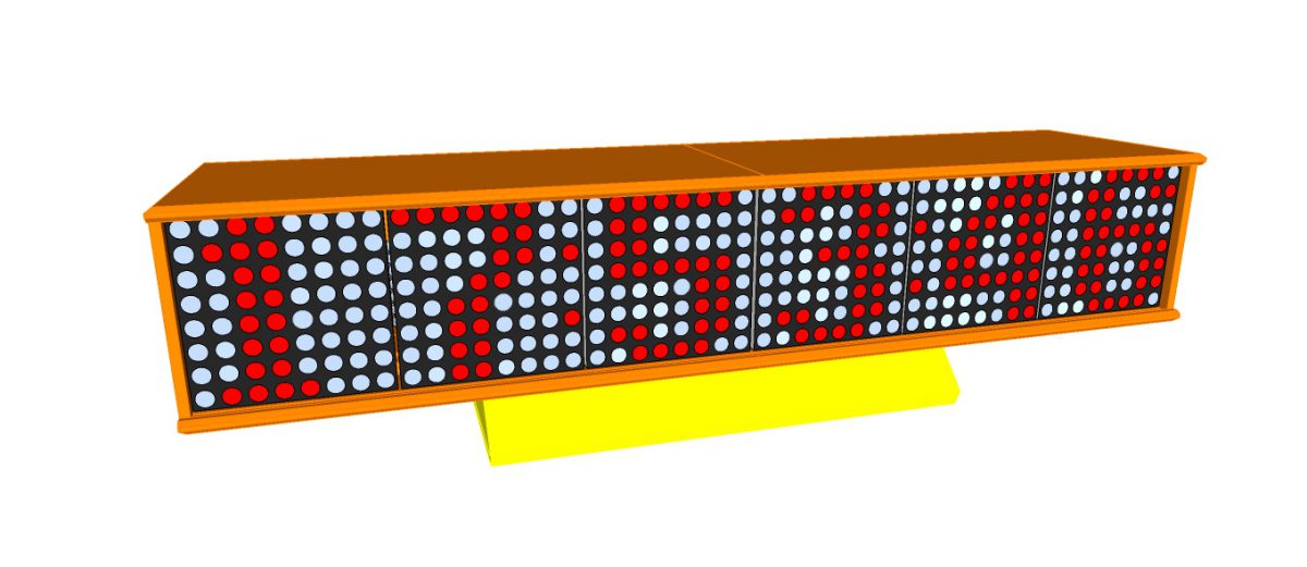
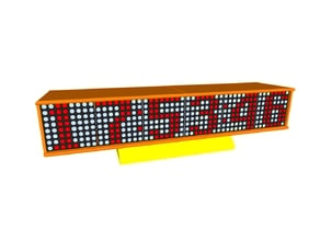
LED Matrix Bar Weather Station V1 – 3D Modeling

Features:
- ESP8266 WeMos D1 mini module which I finally found good application for (now you can buy better cheap ESPs)
- 6 x LEDMatrix module with MAX7219 driver
- supplied directly from USB port with USB plug
- all data are synchronized every 7-8 minutes
- time and date are taken from google.com
- weather informations are grabbed from openweather.org JSON api
- in the future also other news and infos grabbing can be possible
- no hardware RTC clock is necessary
- responsive web(UI) design
- internal temperature, humidity sensor (options – DS18B20, DHT22, DHT12)
- ESP8266 setup and control as a Wi-Fi Web Server (WiFiManager, OTA, mDNS)
- receives a message input from a User Input page, then displays the message on a scrolling LED matrix display.
Parts List:
- 6 x MAX7219 8 x 8 LED Matrix module
- 1 x WeMos D1 mini
- 1 x Interface shield
Additional Parts:
- N x DS18B20 temperature sensor
- 1 x DHT22 temperature and humidity sensor
- 1 x DHT12 temperature and humidity sensor
- N x WS2812B RGB LED
Source code is available here:
The code is being cleaned up. Please wait… I’ll share it soon.
3D Parts:
https://www.thingiverse.com/thing:2650808
NOTE: Recently added support for rotated LED Matrices
The open source ProfileBlock hardware and software is free and made with love. Please show your level of support with a voluntary donation.
Donate:
https://www.paypal.com/cgi-bin/webscr?cmd=_s-xclick&hosted_button_id=RDN7ZGAVFS5UE
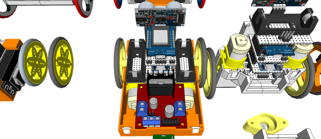
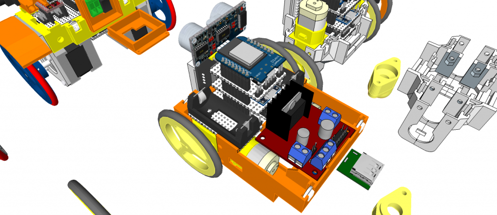
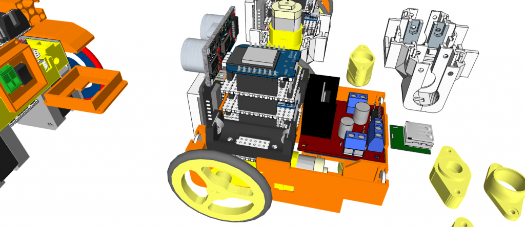
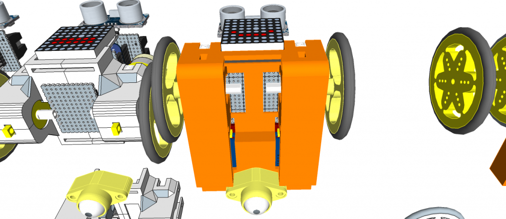
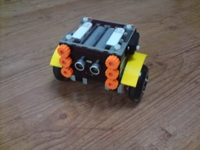
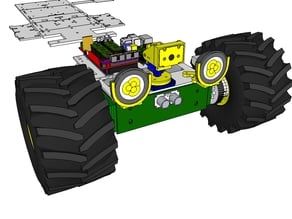
miniMe™ – DIY mini Robot Platform – Design Concepts
miniMe™ is 3D printing DIY mini robot platform
- Balancing Robot
- Rover
- Line Tracer
- Etc…
miniMe-BB: TT motor type
 miniMe-BB: N20 motor type
miniMe-BB: SG90 Servo Motor type
miniMe-Rover: Servo motor type (Standard Servo)
miniMe-Rover: TT motor type

Designs – pinshape


Designs – Thingiverse
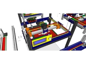
PANDORA Jr. DXs – DIY 3D Printer – 3D Design Conceptby ZalophusDec 12, 2017
LED Matrix Bar Weather Station V1by ZalophusDec 5, 2017
ProfileBlock™ – Balancing Robot – DIY Robot Platformby ZalophusNov 12, 2017
ProfileBlock™ – DIY Robot Platform – Design Conceptsby ZalophusApr 19, 2017
Project Hexapod Robot – H1 – Design conceptby ZalophusOct 1, 2016
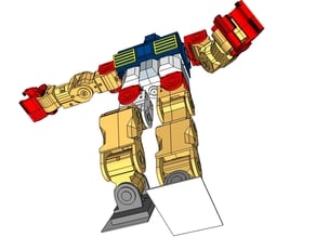
Project Humanoid Robot – M1 – Design conceptby ZalophusOct 1, 2016
Super Ultra Compact Pan/Tilt Camera Mount – V2by ZalophusOct 1, 2016
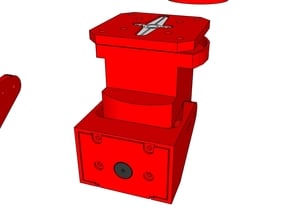
Super Ultra Compact Pan/Tilt Camera Mount – V1 Upgradeby ZalophusJan 4, 2016
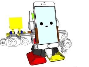
MobBob V2 Remix Upgrade – Smart Phone Controlled Robotby ZalophusJan 4, 2016
CapBot – DIY Web Controlled Camera RoBotby ZalophusJan 3, 2016
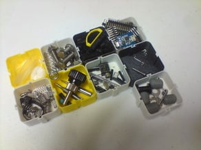
Modular Holderby ZalophusDec 30, 2015
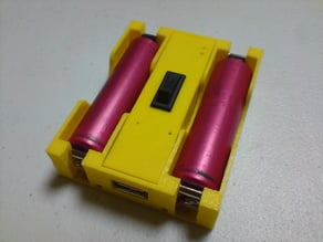
18650 x 2 Battery Bankby ZalophusDec 30, 2015
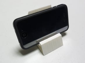
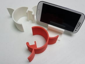
Smartphone Stand Type C (Clip-Y)by ZalophusDec 30, 2015
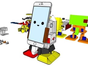
MobBob V2 Remix – Smart Phone Controlled Robotby ZalophusDec 30, 2015
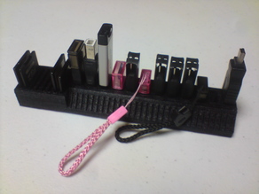
My Customized USB stick and SD card holderby ZalophusDec 23, 2015
Modular Holderby ZalophusOct 23, 2015
Binocular Tripod Adapterby ZalophusSep 11, 2015
Smartphone Stand Type C (Clip)by ZalophusAug 26, 2015
Smartphone Stand Type D (Delta)by ZalophusAug 22, 2015
Smartphone Stand Type F (Fire)by ZalophusAug 17, 2015
Smartphone Stand Type B (Beta)by ZalophusAug 17, 2015
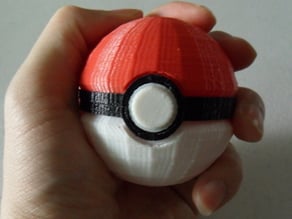
PokeBall – Upgrade Ball Caseby ZalophusJul 28, 2015
Ball Caseby ZalophusJul 19, 2015
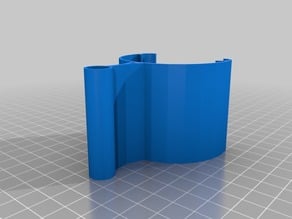
Barrelby ZalophusJul 17, 2015
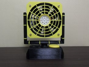
Desktop Cooling FAN & LED Light – DeskFAN 3D Designby ZalophusJul 13, 2015
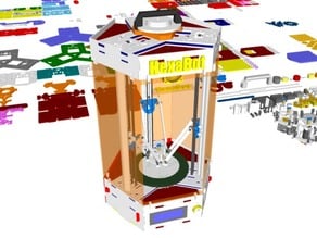
HexaBot – DIY Delta 3D Printer – 3D Designby ZalophusJul 9, 2015
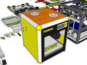
PANDORA DXs – DIY 3D Printer – 3D Designby ZalophusJul 9, 2015
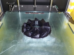
FAN 90mm Replacementby ZalophusJul 7, 2015
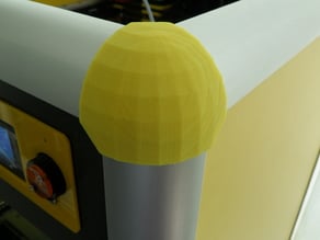
PANDORA DXs – Profile DRF 3030 Corner Coverby ZalophusJul 7, 2015
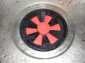
Kitchen Sink Drain Coverby ZalophusJul 7, 2015
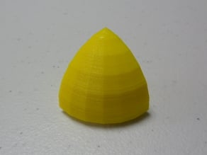
Profile DRF 3030 Corner Capby ZalophusJun 2, 2014
Super Ultra Compact Pan Tilt Camera Mount – V1by ZalophusJun 2, 2014
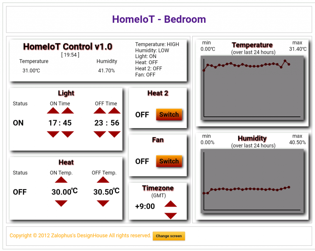
HomeIoT Control v1.0 – with WiFi web server


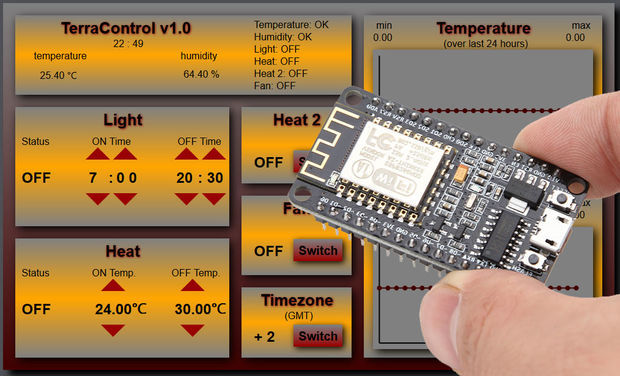
TerraControl – with NodeMCU Webserver

UPDATE 3: Version 1.3
I’m working on making the code as user friendly as possible but it’s going to be a long run. I’d like to have separate html and css files but I’m still figuring it out. For now, few changes…:
- ! ! ! included mDNS protocol, so from now on you don’t need IP address to connect to your NodeMCU, simply put terracontrol.local in your browser and you are done (you have to be on the same network, of course)
- separate file for setting up the variables (setting.h). Unzip the file to your Projects folder, when you open the *.ino file, setting.h should be opened as well.
UPDATE 2: Version 1.2
- improved graph displaying range
- new values in graphs are moved to the end of array, not starting from the beginning again
- improved light setting – it is now unlimited (ON time can now be later than OFF time)
- code for manual defining your own server is in one place and commented by default (i.e. it is on automatic setting)
- clearer information in serial monitor
- unified function for min/max values in array
- new function for printing out minute values
UPDATE 1: Please see the version 1.1 I got the graphs and statistics working! Well, sort of…the range is still not as I want it to be, but at least now it is correctly displaying min and max. Plus new mouseover feature for the individual values in the graph.
After my first attempt to create controlled terrarium using Arduino board I got my hands on NodeMCU 12E board and I knew it was going to be a big step up!
I took me a few days before I began to understand how this board works (thanks to a lot of instructables here and google of course) and the possibilities it had. It think I’m on the right path to create exactly what I was dreaming about for several years…
So what is TerraControl v1.2 capable of?
- 2 automatically controlled relays (light timer and heating)
- 2 manually controlled relays (fan, second heating)
- GMT time change
- Simple graphs with highest/lowest temperature/humidity over the last 24 hours
- Monitoring temperature and humidity in terrarium
- All accessible and adjustable through webserver using HTML and CSS
- NodeMCU Lua 12E board– $3.40
- Relay board – for example – $2.50
- Temperature and humidity sensor DHT22(11) – $3
- given the nature of NodeMCU board (its output is only 3.3v) you will either have to buy 3.3V relay board, or modify 5v board, or buy I2C logic converter module – for example – $0.9
- 5V source (I’m using older usb charger)
- wires
- solder
- case/box
- Arduino IDE
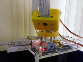
Step 1: Getting the Parts Together
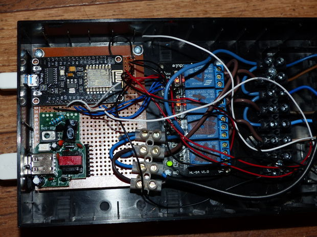
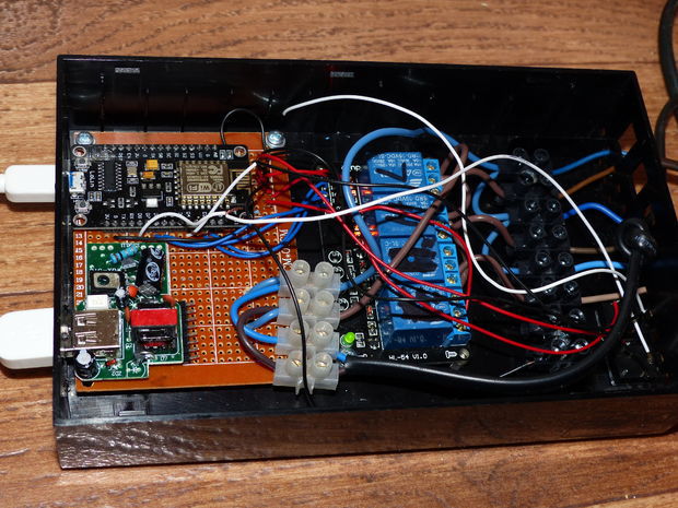
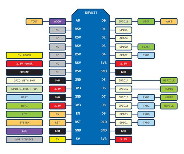
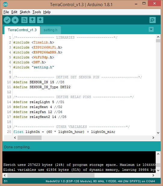
Connecting these parts is easy, just look at the source code and keep in mind that GPIO’s of the NodeMCU board is different from the actual boards description (as seen on the trird picture):
//Define sensor pins
#define SENSOR_IN 15 //D8
#define SENSOR_IN_Type DHT22
//Define Relay pins
#define relayLight 5 //D1
#define relayHeat 4 //D2
#define relayFan 12 //D6
#define relayHeat2 14 //D5
i.e. DHT sensor pin goes to D8 (board’s D3, D4, D8 can’t be used as output but can be used as input), and the relay pins accordingly to the code. Remember, if you are using 5V relay, you need to modify the relay board or use I2C logic converter.
! ! ! IMPORTANT! When uploading the code to the board, you have to disconnect the DHT sensor, otherwise you will get an error when attempting to upload ! ! !
All parts can be powered with 5v power adapter
Step 2: Setup and Customization
Before we upload the code, there are few things that needs to be set up in setting.h:
//You WiFi AP
const char ssid[] = “SSID Name”; // insert your WiFi AP name
const char pass[] = “password”; // insert your WiFi password
// T E R R A R I U M S E T T I N G
float tempMin = 24; // temperature in Celsius for switching the heating ON
float tempMax = 30; // temperature in Celsius for switching the heating OFF
int humMin = 50; // minimum humidity in %
int humMax = 70; // maximum humidity in %
// hour and minute for light to go ON
int lightOn_hour = 7;
int lightOn_min = 0;
// hour and minute for light to go OFF
int lightOff_hour = 20;
int lightOff_min = 30;
// Central European Time (1 for winter time)
int timeZone = 2;
Uncomment the following part of the code if you know how to define your server manually or just run the code and get addresses from the serial monitor.
/*— UNCOMMENT THIS FOR MANUAL SETTING —
IPAddress ip(192, 168, 0, 111); //Node static IP
IPAddress gateway(192, 168, 0, 1);
IPAddress subnet(255, 255, 255, 0);
WiFi.config(ip, gateway, subnet);
*/
All done? Great, let’s move on…

Step 3: Alwas ON/OFF Relay Connection
One thing I wanted was the relay board to be used as little as possible. As you probably know, relays have two possible ways of connection: ON when not used and ON when used. So I connected the light and heating to “ON when not used” (heating is almost always ON and lights are ON for about 13-14 hours every day) and fan and heating 2 to “ON when used” (I barely need to use one of them).
That is why the code for the same function is using different values:
if (heatVal == 1) {
client.println(“ON”);
} else {
client.println(“OFF”); }
AND
if (heat2Val == 1) {
client.println(“OFF”);
} else {
client.println(“ON”); }
You can of course modify the code according to your needs.
Now just connect the DHT sensor and let’s look at the result!
Step 4: Webserver
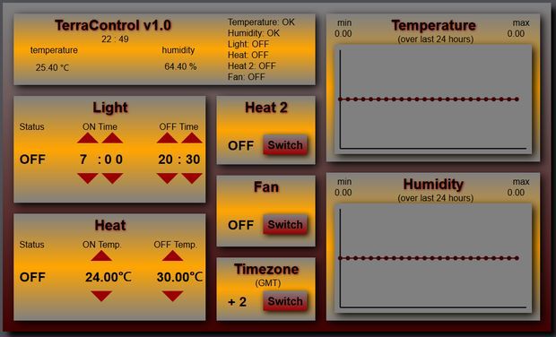
When you open the webserver you will see simple page with all information about your terrarium and some features:
- Light ON/OFF time can be adjusted (step are: 1 hour for hour setting and 5 min for minute setting). At the moment ON time has to be earlier that OFF time (ON 22:30 and OFF 0:30 will not work – yet) – fixed in version 1.2
- Temperature setting (steps are 0.5 degree Celsius)
- Manualy turn ON/OFF other two relays – Fan and Heat 2 and adjust timezone when the time changes
if needed, change your timezones in following part of the code:
if (request.indexOf(“/TIMEZONE_SWITCH”) != -1) {
if (timeZone == 1) {
timeZone = 2;
setSyncProvider(getNtpTime);
} else {
timeZone = 1;
setSyncProvider(getNtpTime);
} }
- Webserver is using automatic time synchronization
Step 5: Disclosure
I know that the HTML and CSS code could be much more simple and the coding is not really user friendly but for the moment it works as it is supposed to (only the graphs are not very accurate but I’m still working on them) and I will get to these points when I start working on version number two. I have already decided to use external power supply (in this version I just stripped the 5v adapter and soldered it inside the box) and I also want the power cables to be more accessible and easier to connect/disconnect. I hope you guys (and your pets) will appreciate this instructable, if you do, please leave a short comment. And of course, suggestions are more than welcome! Thank you