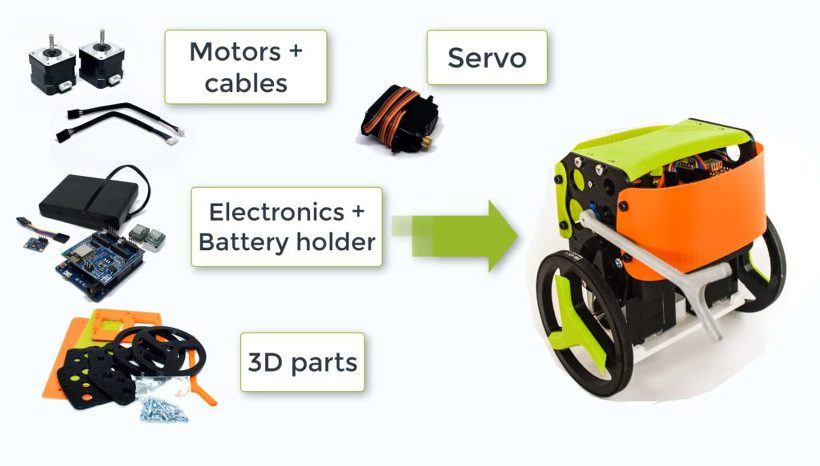
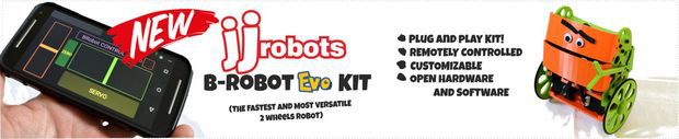
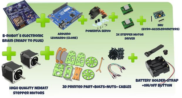
JJrobots´s B-ROBOT EVO 2 Kit. Created to simplify the set up and integration of all the different devices involved in this project.
This COMPLETE VERSION includes all the electronic and hardware components required to create the B-Robot. You just need to assemble everything (optional 3D parts)
STEM education robot: perfect introduction to a robot that solves the inverted pendulum problem. Modify the B-robot EVO 2 as much as you can (both the robot parts themselves or its code) while you have fun!
Perfect to have fun as you learn robotics (Take a look to the Robotics Challenges!)
Now can use regular AA batteries (or a 3 cells LIPO battery)
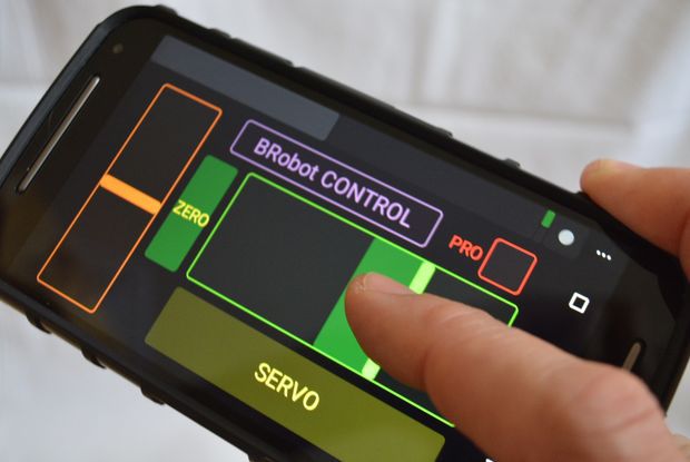
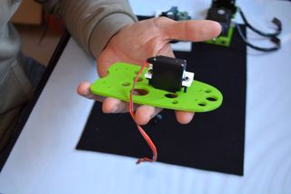
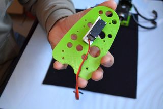
Two SERVO outputs (one used for the ARM). Both can be controlled from the jjRobots APP
Easier to print and using less plastic
PRO MODE can be activated from your smartphone/Tablet (increased agility and velocity)
Increased WIFI range (up to 40 meters)
Battery status
“Tilt angle” displayed in real time on your smartphone screen
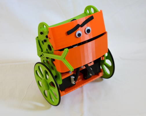
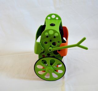
Personalise your B-robot to fight, create your own weapons, increase the size of the wheels… it is up to you! Take a look to some parts (and send us yours!)Customise your own bumper using the online tool at Thingiverse
B-ROBOT Evo 2 Features:
STEM education robot. In addition to being fun, the B-robot EVO 2 engage beginners and advanced students and incorporate many of the fundamental STEM concepts providing a learning platform that everyone enjoys
Perfect have fun as you learn about robotics (Take a look to the Robotics Challenges!)
Open Robot project: code and 3D design files are open and shared. You could personalise your robot as much as you want.
DIY & Hackeable: BROBOT is not a closed final product, BROBOT is an open, modifiable and hackeable platform, perfect to learn and play as much as you want!
Develop your own apps: You could modify the source code of BROBOT to perform new tasks but the communication protocol is also open so you can develop your own IOS, Android, PC remote apps to control your BROBOT!
Learn: BROBOT is a JJROBOTS product and this mean that you will receive a well documented project (source code and external documentation). We want you know all that is happening inside your Robot! This is ideal for learning and teaching technology. We will provide very good documentation. How we are controlling the motors, how we read and integrate the information from gyros and accelerometers, how we are controlling de stability of the robot, how we communicate with the control apps, etc…
– Build with your kids, at school, for yourself… this is a unique gadget. A perfect STEM education robot
– This self balancing robot has a medium size, perfect to carry your own beer (or mineral water ;-))
– There is a community behind BROBOT so you will have a forum to ask questions, share your experiences, MODs/ Hacks and contact other users…
– You can use these self balancing robot parts to create more robots or gadgets, keep in mind all the devices used in a BROBOT are standard electronic devices with a lot of potential. In the JJROBOTS community we want to show you how! You are now buying a self balancing robot, you are buying your a versatile set of electronics and ancillary devices.
How does this robot work? Can I adjust its behaviour? And modify it?
STEM education robot: In addition to being fun, the B-robot EVO 2 engage beginners and advanced students and incorporate many of the fundamental STEM concepts providing a learning platform that everyone enjoys
Bring a beverage can to the other side of the room not dropping it, race against other B-robots with different configurations and add-ons and understand what it is going on. The B-robot EVO 2 is a very versatile and fun STEM learning robot
CUSTOMISE YOUR ROBOT!
Create your own bumpers and personalise your B-robot with the online customisation tool on Thingiverse
Better than a bunch of photos we have created an Assembly guide video. Some steps, like how to program the Arduino, controlling your robot or Troubleshooting are listed below. The interactive 3D model will help you to get a good idea about how the B-robot EVO looks.
My B-robot is not responding to the command sent from my smartphone/tablet
Check you are connected to the JJROBOTS_XX netwrok using the correct password (by default: 87654321) and your device has not blocked the data traffic to the B-robot (stay always connected to the robot)
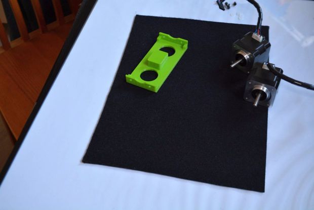
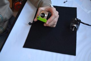
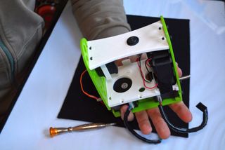
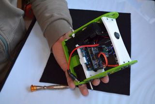
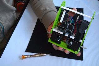
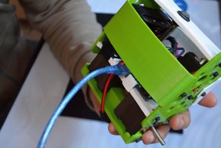
The IMU gets loose/ the i2C cable is too short
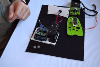
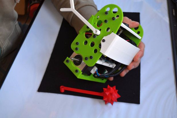
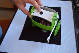
The gyroscope (IMU) is one of the most important element in this robot. It provides the current angle of the robot updating its value hundred times per second. The protocol used to send the data is quite sensitive to any electromagnetic interference so a very short cable is needed to connect the IMU and the Brain Shield. At the same time, vibrations create false angle measurements so we have to isolate the Brobot´s main frame vibrations from the IMU: that is the reason to use a double sided sticky pad to fix the IMU to the Brain Shield.
Place the IMU as indicated above: Close to the Brain Shield´s i2C connector. Bend the cable if needed. If you place the IMU as above, there should not be any lateral force pushing the IMU out of place
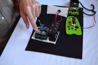
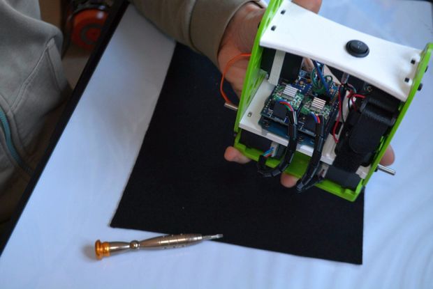
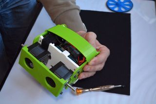
My B-robot lacks of power or fall without reason
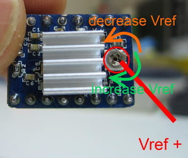
Adjust the current delivered by the stepper motors drivers. Use a screwdriver and gently rotate the screws indicated on the photo below. Rotating 10º-30º is more than enough.
Clockwise rotation: increase the power delivered to the motors
A4988 STEPPER MOTOR DRIVERS output current potentiometer
My B-robot can not stand up by itself.
If everything is ok, the B-robot only needs a little bit of help from the servo to stand up by itself. Take a look to the video below. If your robot does not behave like in the video, adjust the stepper motor drivers output power (instructions above). Keep in mind that the bumpers have two functions here: protect the electronics+robot and help it to stand up easily.
Video Player
DEBUG MODE
There is a DEBUG MODE inside the B-robot CODE. This MODE will allow you the debug the behaviour of the robot if you are having issues. Please, refer to the B-robot community if you have problems or questions.
Look at the sketch line “#define DEBUG 0″ and change the 0 to 1…8 depending on what info you want to get. Take a look to the CODE below:
//Serial.print(“\t”);
mpu.resetFIFO(); // We always reset FIFO
// We calculate the estimated robot speed:
// Estimated_Speed = angular_velocity_of_stepper_motors(combined) – angular_velocity_of_robot(angle measured by IMU)
actual_robot_speed_Old = actual_robot_speed;
actual_robot_speed = (speed_M1 + speed_M2)/2; // Positive: forward
int16_t angular_velocity = (angle_adjusted-angle_adjusted_Old)*90.0; // 90 is an empirical extracted factor to adjust for real units
int16_t estimated_speed = -actual_robot_speed_Old – angular_velocity; // We use robot_speed(t-1) or (t-2) to compensate the delay
estimated_speed_filtered = estimated_speed_filtered*0.95 + (float)estimated_speed*0.05;
// SPEED CONTROL: This is a PI controller.
// input:user throttle, variable: estimated robot speed, output: target robot angle to get the desired speed
//target_angle = (target_angle + speedPControl(estimated_speed_filtered,throttle,Kp_thr))/2.0; // Some filtering : Average with previous output
//target_angle = target_angle*0.3 + speedPIControl(dt,estimated_speed_filtered,throttle,Kp_thr,Ki_thr)*0.7; // Some filtering
target_angle = speedPIControl(dt,estimated_speed_filtered,throttle,Kp_thr,Ki_thr);
target_angle = constrain(target_angle,-max_target_angle,max_target_angle); // limited output
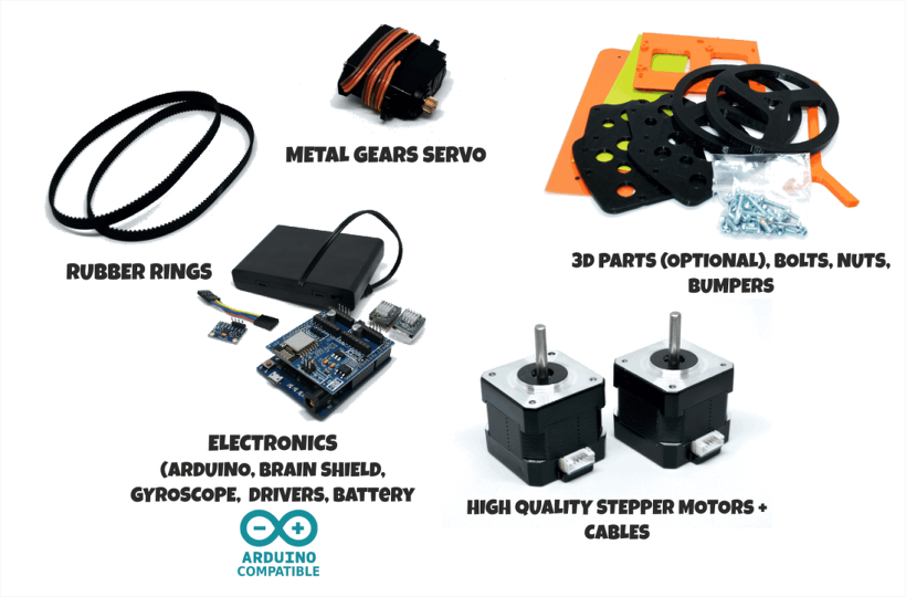
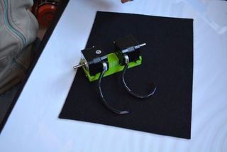
There are several options for motors: DC, Brushless, Steppers… We choose stepper motors because they have enough torque, you could connect the wheels directly without gears that generate some backslash (this is a common problem in balancing robots), they have good bearings and you will be able to control the speed of the motors with accuracy. In standard sizes these motors are cheap (we use the same motors used on a regular 3D printers) and the drivers are cheap and easy to interface with Arduino too.
Why you use a Wifi connection?
Using a Wifi connection allow us to work with a lot of devices (Smartphones, Tablets, PCs…) Bluetooth devices are cheaper but their range is usually shorter. Old devices are not supported and you could not connect it to Internet easily. The Wifi module that we recommend, allow us to create an Access Point, so you don’t need to use an existing Wifi infrastructure (cheap Wifi modules don´t let you do this). You can connect your device directly to the Robot anywhere but if you prefer you can hack it and use your own infrastructure therefore controlling your robot (or whatever you have created) over the Internet from any remote place in the world! (Cool, isn´t it?)
Why BROBOT?
Self balancing robots are fun to see and play. A self balancing robot requires sensors and control algorithms. You will find all the HOWTO and technical documents which explains the “behind the scenes” in JJROBOTS. Learn electronics and robotics creating your own BROBOT from scratch!.
There are some commercial solutions to the balancing robot, but here we want to share knowledge and thoughts. You can use the BROBOT parts to create more robots or gadgets, keep in mind all the devices used in a BROBOT are standard devices/electronics with a lot of potential. In the JJROBOTS community we want to show you how! You are now buying a self balancing robot, your are buying your own electronic and ancillary devices!
Thinking about creating a GPS self guidance robot? a modified version of BROBOT is your robot!
How much payload could carry BROBOT?
BROBOT could easily carry your soft-drink cans. We have tested with 500g of payload with success. More weight makes the robot more unstable but this could be fun also, isn’t it?
Why use stepper motors for a balancing robot?
There are several options for motors, DC, Brushless, Steppers… We choose stepper motors because they have enough torque, you could connect the wheels directly without gears that generate some backslash, they have good bearings and you could control the speed of the motors very precisely. Also they are cheap and the drivers too…
Could I use rechargeable batteries of Lipo batteries?
Yes, you could use standard AA batteries (alkaline recommended), AA rechargeable batteries (e.g. NiMh) or you could optionally use a 3S Lipo battery. Run Lipo batteries at your own responsibility.
What is the runtime of BROBOT?
With rechargeable AA batteries (e.g. Ni-Mh 2100mAh) you could expect around half to an hour of runtime
Could BROBOT work without the wifi module?
Yes, BROBOT could work and keep its stability. But, of course you could not control it without the module.
Could I change the name of the Wifi network that BROBOT generate?
Yes, on the configuration sketch you could change the name and also some other internet configurations. You could also connect BROBOT with your existing Wifi network
Is this a project for an Arduino beginner?
Well, BROBOT is not an easy “beginner project”, but it has a lot of documentation so you have a platform to grow your skills. You could first mount your BROBOT following the instructions and it should work OK, then you could start understanding some parts of the code and finally writing your own pieces of code…
For example it could be easily (there are tutorials for this) to write your code so the robot automatically move the arm and spin itself if you don’t send a command in 10 seconds…
More advanced hacks: Convert to a totally autonomous robot with obstacle avoiding adding a SONAR, convert to a follow line robot, and so on…
Why BROBOT electronics are not so cheap?
We are a really small startup (2 persons in our free time) and now we could only run small batch of electronics. As yo know the price of electronics drops quickly in high volume productions but we are starting… If we sell many boards and we could run more volume productions we will drop the prices!!. JJROBOTS didn´t born to get money, our spirit is to sell “good products” to found our next projects and spread the robotics knowledge
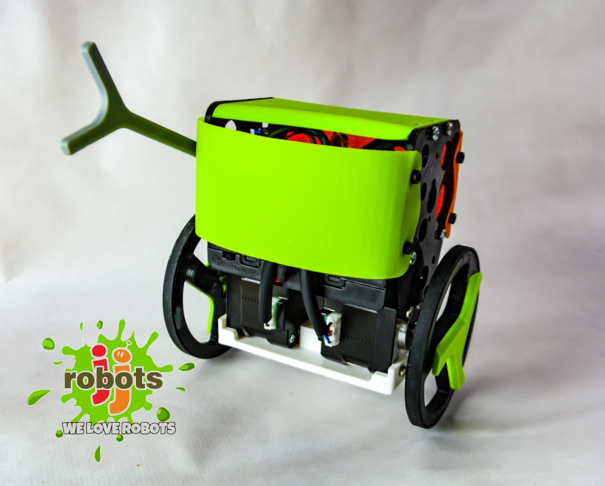
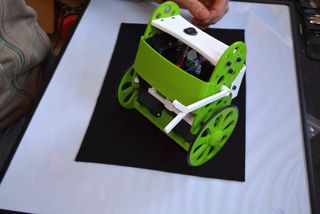
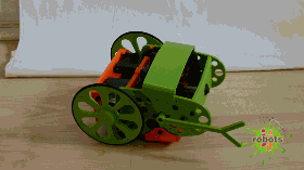
B-ROBOT EVO is a remotely controlled self balancing arduino robot created with 3D printed parts. With only two wheels, B-ROBOT is able to maintain its balance all the time by using his internal sensors and driving the motors. You can control your Robot, making him move or spin, by sending commands via a Smartphone, Tablet or PC while it maintains its balance.
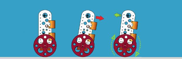
This self balancing robot reads his inertial sensors (accelerometers and gyroscopes integrated on the MPU6000 chip) 200 times per second. He calculates his attitude (angle with respect to the horizon) and compares this angle with the target angle (0º if he wants to maintain balance without moving, or a positive or negative angle if he wants to move forward or backwards). Using the difference between the target angle (let’s say 0º) and actual angle (let’s say 3º) he drives a Control System to send the right commands to the motors to maintain his balance. The commands to the motors are accelerations. For example if the robot is tilted forward (angle of robot is 3º) then he sends a command to the motors to accelerate forward until this angle is reduced to zero to preserve the balance.
Step 1: A Bit More in Depth…
The physical problem that B-ROBOT solves is called the Inverted Pendulum. This is the same mechanism you need to balance an umbrella above your hand. The pivot point is under the center of mass of the object. More information on Inverted Pendulum here. The mathematical solution to the problem is not easy but we don’t need to understand it in order to solve our robot´s balance issue. What we need to know is how should do to restore the robot´s balance so we can implement a Control Algorithm to resolve the problem.
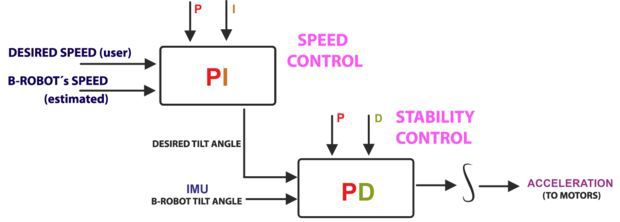
A Control System is very useful in Robotics (an Industrial automation). Basically it´s a code that receives information from sensors and target commands as inputs and creates, in consequence, output signals to drive the Robot actuators (the motors in our example) in order to regulate the system. We are using a PID controller (Proportional + Derivative + Integral). This type of control has 3 constants to adjust kP,kD,kI. From Wikipedia: “A PID controller calculates an ‘error’ value as the difference between a measured [Input] and a desired setpoint. The controller attempts to minimize the error by adjusting [an Output].” So, you tell the PID what to measure (the “Input”),where you want that measurement to be (the “Setpoint”,) and the variable you wish to adjust to make that happen (the “Output”.)
The PID then adjusts the output trying to make the input equal the setpoint. For reference, a water tank we want to fill up to a level, the Input, Setpoint, and Output would be the level according to the water level sensor, the desired water level and the water pumped into the tank. kP is the Proportional part and is the main part of the control, this part is proportional to the error. kD is the Derivative part and is applied to the derivative of the error. This part depends on the dynamics of the system (depends on the robot,´s weight motors, inertias…). The last one, kI is applied to the integral of the error and is used to reduce steady errors, it is like a trim on the final output (think in the trim buttons on an RC car steering wheel to make the car go totally straight, kI removes the offset between the target required and the actual value).
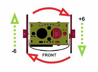
On B-ROBOT the steering command from the user is added to the motors output (one motor with a positive sign and the other with a negative sign). For example if the user sends the steering command 6 to turn to the right (from -10 to 10) we need to add 6 to the left motor value and subtract 6 from the right motor. If the robot is not moving forward or backwards, the result of the steering command is a spin of the robot
Step 2: What About the Remote Control?
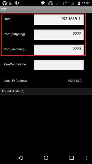
We wanted B-ROBOT to be controlled by the user from almost any existing device, but we don´t want to develop a lot of different interfaces for different systems (Android, IOS, PC-windows…). Moreover, we decided to use existing (and powerful) protocols to control “things” and we found (some years ago) a protocol called OSC(Open Sound Control, more info here) used to control musical instruments like synthesizers. Very visual and powerful (we can display volume control, equalizers, lights…and create our own). To remotely control B-robot, we use OSC protocol over an Internet connection (Wifi module) using UDP packets. This is a lightweight and efficient way to send commands to our Robots!. We could also personalize the Interface we are using in our device so we will be able to control anything! (well…almost) What we need to do is to implement a lightweight library for Arduino in order to support this protocol (easy). We only use a subset of the OSC protocol to keep things small.
8xAA battery holder (for NiMh or alkaline batteries)
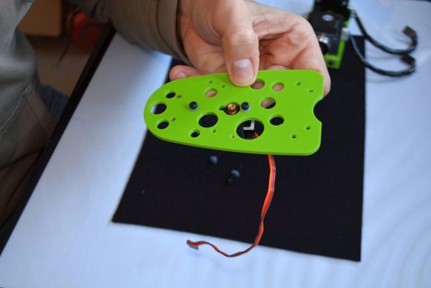
OPTIONAL: Mini servo (21g) to move the arm (this is a fun feature)
The easy way to get everything is buying from us (and that encourages us to keep doing these robots) here (plus bolts, nuts, strap…)
HINT:
We are working on other robots that are using the same electronics and ancillary elements. If you get the items above you will be capable of assemble new different robots soon. Take a look to them at the last step
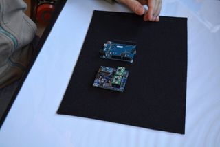
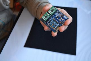
Step 4: Programming the ARDUINO LEONARDO
a) Install the Arduino IDE on your PC from (skip this step if you have arduino already installed)
This B-robot code has been tested and developed on IDE version 1.6.5
b) Install the libraries (https://github.com/jjrobots/B-ROBOT/tree/master/libraries) Copy the folders inside the /libraries into the Arduino/libraries folder on your hard drive
JJROBOTS_BROBOT
JJROBOTS_OSC
I2Cdev
MPU6050
c) Get the main CODE (https://github.com/jjrobots/B-ROBOT/tree/master/BROBOT).
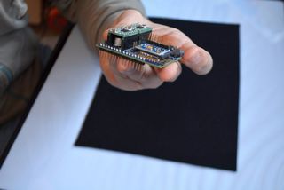
d) Compile and send the code to the Arduino Leonardo:
Open your Arduino IDE
Open the main code in /BROBOT/BROBOT.ino
Connect your Leonardo board with the USB to the PC
Note: If this is the first time you connect a Leonardo board to your PC maybe you will need to install the driver.
Select the board Leonardo (tools->board)
Select the serial port that appears on the tools->Serial port
Send the code to the board
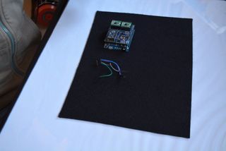
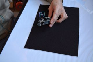
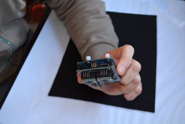
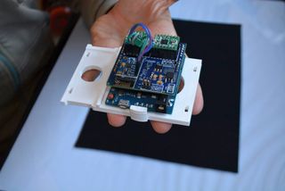
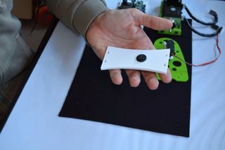
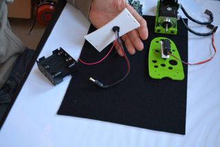
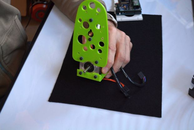
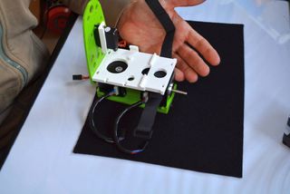
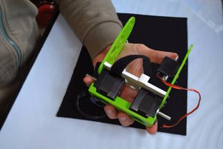
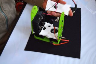
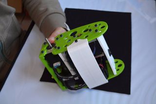
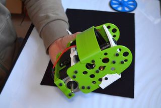
Step 5: Assemble the B-robot Frame+ Ancillary Elements
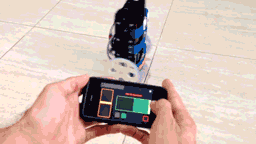
Step 6: (Optional But Recommended) Controlling the B-robot Using WIFI
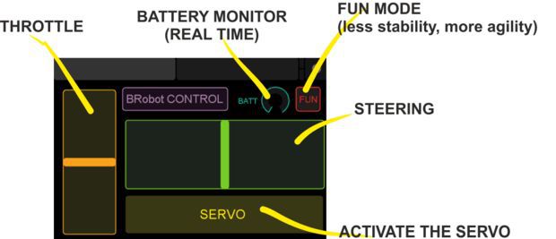
Setting up the TouchOSC software: If you are going to use the Touch OSC software to control the B-robot (and according to the current B-robot´s CODE available for the Arduino Leonardo), you will need to set these parameters in the TouchOSC like is shown in the images above.
Download the B-robot control layout (you can modify it if you want to) and install it using the OSCtouch APP
Once the B.robot is switched on, a new WIFI signal will appear: “JJROBOTS-XX”. You will need to connect the controlling device to this network using the default WIFI password: 87654321
An OSC control software alternative: OSCillation and how to use it (Thanks Patrick!)
Step 7: Powering Up the B-robot:
Lay down the B-robot on a static horizontal position in order to let it calibrate itself after powering it up.
Turn the B-robot ON
Let the B-robot 10 seconds to calibrate itself. Once self-calibrated, B-robot will spin its wheels a little.
Time to stand up!: Use its arm or help it to stand up.
HINT: If the stepper motors do not have enough power to spin the wheels, try to adjust the current output in the A4988 stepper motor drivers rotating the screw indicated in the photo
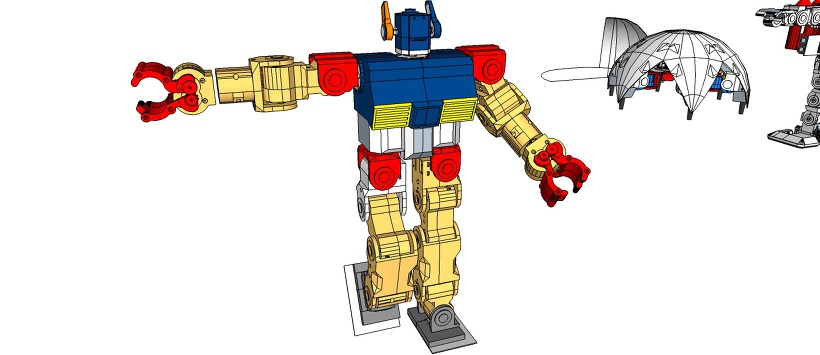
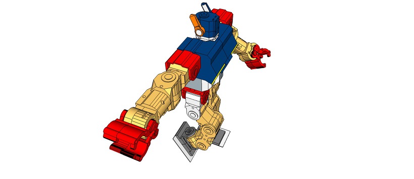
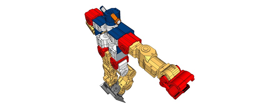
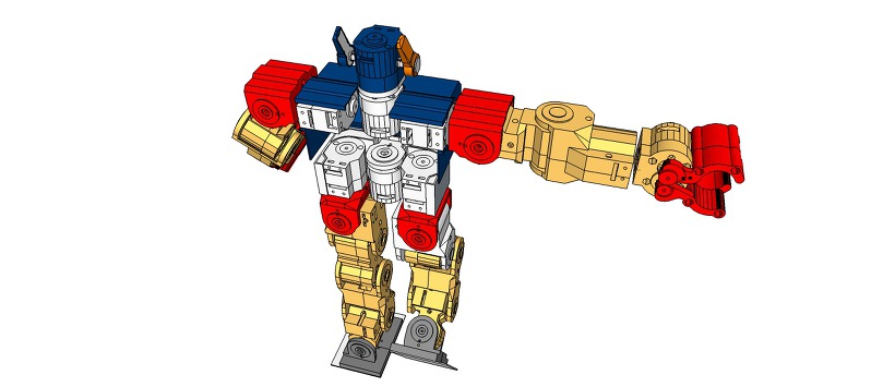
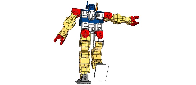
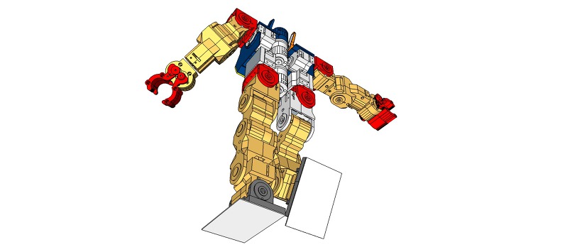
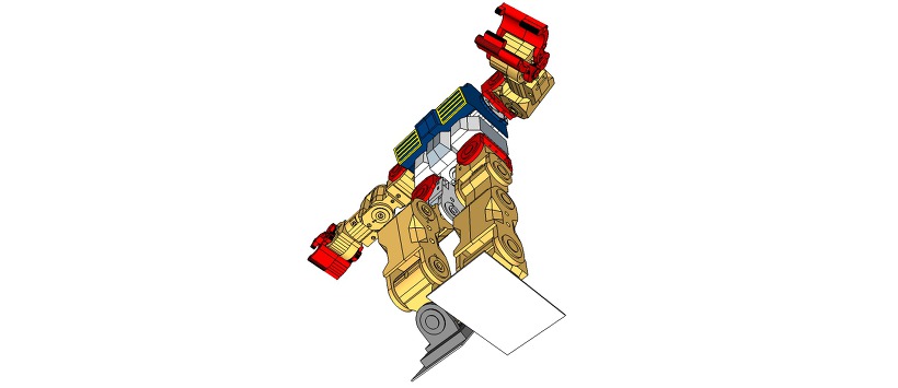
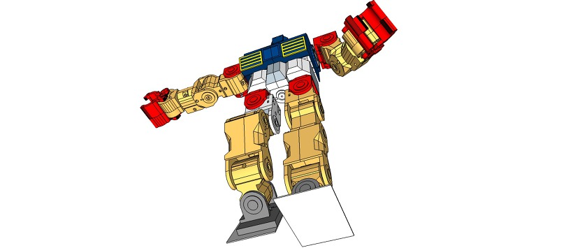
3D Design Tool: SketchUp Pro
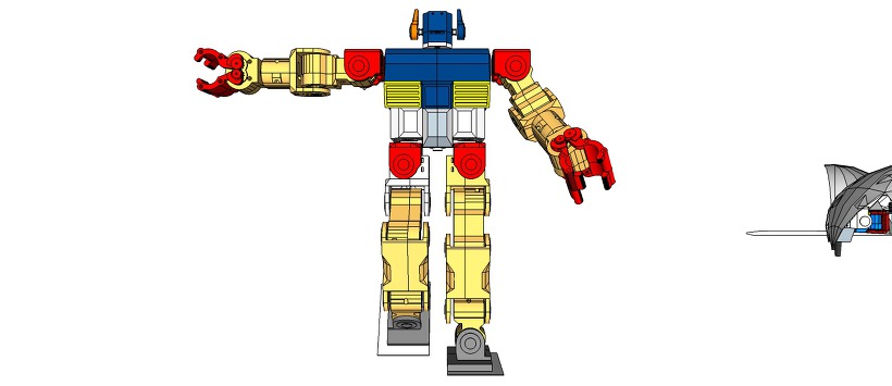
Design concept: RAPIRO – The Humanoid Robot and Gundam
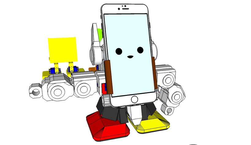
This is an upgrade version of my MobBob V2 Remix robot.
MobBob is a smart phone controlled robot. By harnessing the power of your smart phone, MobBob is a walking, talking robot with voice recognition and computer vision that you can build for around $35. I will be continuing to extend his features over time. I want MobBob to be a companion robot that everyone can afford and have fun with.
Support standard 9g servos [previously I was using Tower Pro SG90 servos]
Make everything easier to assemble [no more need for glue]
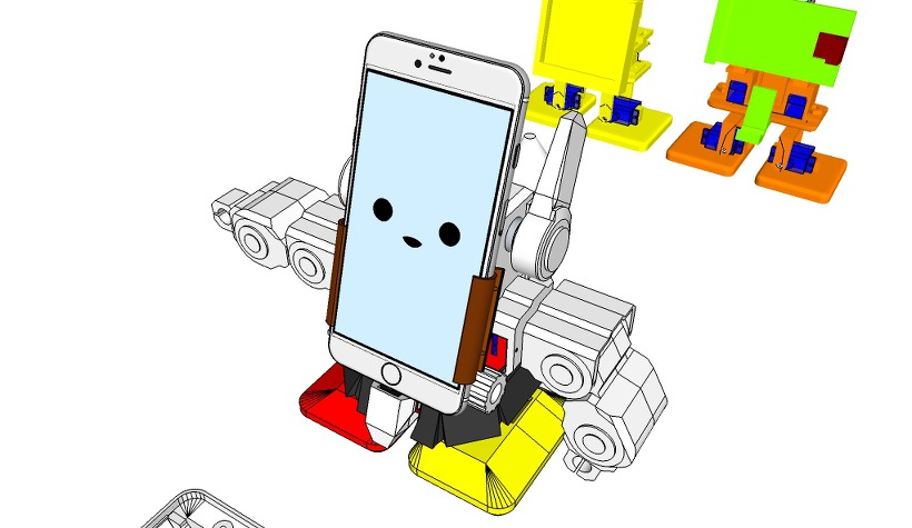
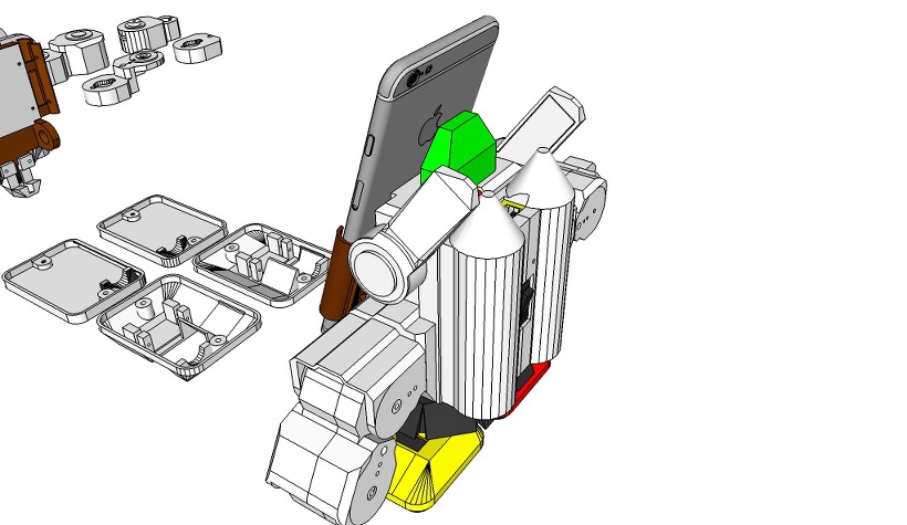
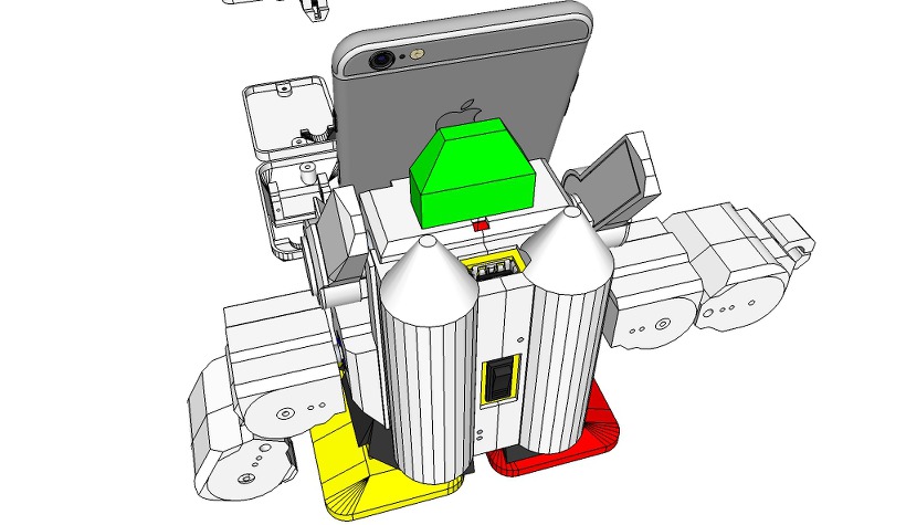
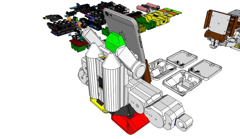
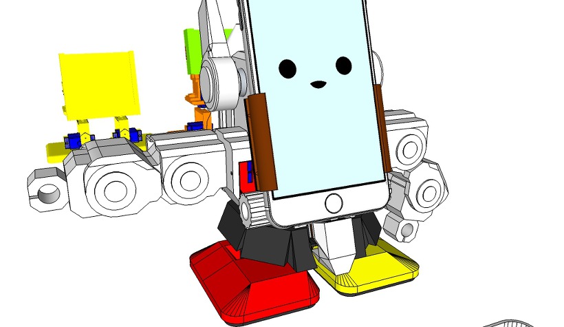
Make it easier to adapt/modify for other phones. The new bracket system made it easier to exchange a new phone / the battery holder.
Also, in my V2 Remix Upgrade build, I’m also using the Arduino Nano instead of the DIY Nano shield, so the entire build is smaller and tidier. 🙂
MobBob V2 Remix Upgrade uses the same software as the original RAPIRO.
You can find more detailed build and wiring instructions here:
…coming soon…
The parts that you need to print:
1 x Leg Left
1 x Leg Right
1 x Foot Left Floor
1 x Foot Right Floor
1 x Foot Left Top
1 x Foot Right Top
1 x Waist
1 x Arduino Nano Holder
1 x Phone Mount Base
2 x Phone Mount Side
1 x Phone Mount Gear
1 x Phone Mount Back Plate
1 x Phone Mount Conn
2 x Phone Mount Bolt
2 x Phone Mount Nut
1 x Battery Bank Rack [18650 x 2] or Power Bank
1 x Battery Mount Cover or PowerBank Hook
1 x Jacket
1 x Cap
1 x Hand Back Left
1 x Hand Front Left
1 x Arm Back Left
1 x Arm Front Left
1 x Shoulder Left
1 x Hand Back Right
1 x Hand Front Right
1 x Arm Back Right
1 x Arm Front Right
1 x Shoulder Right
The non-3D printed parts you need are:
6 x Tower Pro SG90 servos [for Shoulders, Arms and Hands]
4 x EMAX ES08MA II Mini Metal Gear Analog Servo [Strengthening the power of the Legs and Foots]
1 x Arduino Nano ATmega328 [see note below]
1 x HM-10 BLE Bluetooth 4.0 CC2540 CC2541 Serial Wireless Module [or HC-05]
1 x 5V Micro USB 1A Lithium Battery Charging Board [see note below]
1 x DC-DC Converter Step Up Boost Module 2-5V to 5V 1.2A
1 x Rectangle On/Off Long Rocker Switch SPST
2 x Snap-In Single ‘A’-‘AA’ Battery Contacts 209 [KEYSTONE ELECTRONICS CORP.]
2 x Snap-In Single ‘A’-‘AA’ Battery Contacts 228 [KEYSTONE ELECTRONICS CORP.]
2 x 18650 Lithium ion Batteries
1 x 300mm USB 2.0 A Male to Micro USB B 5pin + Mini B Male Y Splitter Cable
1 x Smart Phone [see note below]
4 x M3 5mm [for Foot Cover]
2 x M2 10mm [for Phone Connect]
4 x M2 5mm [for Phone Mount Back Plate]
2 x 2mm 5mm Tapping screw [for Foot servos]
2 x 2mm 8mm Tapping screw [for Hip servos]
2 x 1mm 5mm Tapping screw [for Foot servos hone]
2 x 1mm 8mm Tapping screw [for Hip servos hone and Shoulder]
2 x M3 15mm [for Jacket]
2 x M3 Nut [for Jacket]
4 x 2mm 15mm Tapping screw [for Jacket]
12 x M2 15mm [for Arm and Hand]
[Note: I got the servos, Arduino Nano, Bluetooth Module and Battery for under $30.]
Arduino Nano:
This is a small, Arduino compatible ATmega328 board with DIY extension board. MobBob V2 app connects to the Bluetooth module using its Bluetooth LE service. The app to support other Bluetooth cards.
Battery Extender:
You can use other batteries that provide 5V with a steady current. If you use other batteries, you may need to adapt the battery rack for your battery’s size.
Use 18650 Lithium Battery Charging Board With Protection Charger Module and Step Up Boost Module 3.7V to 5V for Smart Phone http://www.thingiverse.com/thing:1235749
Smart Phone:
You can use other Android Smart Phones with This app.
You do not need to adapt the size of the phone holder for your phone. The app has been successfully tested with Nexus and Samsung, LG phones, but should work on other Android phones.
Instructions:
Print all the required parts
Get all the non-3D printed parts
Assemble as per the photos – I’ll be writing some more detailed instructions on my website soon!
Install the Arduino code from the GitHub link in the description – You will need to update the Arduino pins in the code to match yours, and probably update the centering values for the servos.
Install the Android app from the link in the description.
Have fun!
If you hit any problems, please post a question on this website: [http://www.rapiro.com], here, or on YouTube channel. A few people have built RAPIRO now, so there are people around who can help.
Coming soon update!!
The open source Mobbob V2 software and hardware is free and made with love. Please show your level of support with a voluntary donation.
by ShotaIshiwatari is licensed under the Creative Commons – Public Domain Dedication license.
modified by Zalophus
on the command line, enter:
// #M1 – robot will move forward
// #M2 – robot will move backward
// #M3 – robot will turn right
// #M4 – robot will turn left
// #M5 – robot will raise his hand and wave the left hand. LED will become green and flashing
// #M6 – robot will lower his left hand. LED will become Yellow
// #M7 – robot will move both arm and contract his hands. LED will become Blue
// #M8 – robot will wave goodbye with his left arm. LED will become RED.
// #M9 – robot will raise its right arm and move its waist. LED will become BLUE
// #M0 – robot will go to initial position
CAPS LOCK is important when you input a command via the serial monitor..
Reading through the source code.
Each movement of the preset (# M1 ~ # M9), consists of pattern of 8 frames.
Each frame is defined values uint8_t type sixteen (motion).
This can be changed modifying the number of frame per pattern.MAXFN
Lets take #M0 for example:
I put numbers so you can visualy make sense of what a pattern is, and what a frame contain.
Movements consist of pattern. Pattern are made of frames. Each frame contrain the rotation angle of every servo, the values of the RGB LED and a Time to perform the action.
Head horizontal rotation angle (Head yaw) (left) 180 <—> 0 (right)
Hip horizontal rotation angle (Waist yaw) (left) 180 <—> 0 (right)
Right shoulder up and down angle (R Shoulder yaw) (bottom) 0 <—> 180 (above)
Open right shoulder angle (R Shoulder pitch) (closed) 90 <—> 180 (open)
Right hand opening and closing angle (R Hand grip) (closed) 50 <—> 110 (open)
Left shoulder up and down angle (L Shoulder yaw) (bottom) 180 <—> 0 (top)
Open left shoulder angle (L Shoulder pitch) (closed) 90 <-> 0 (open)
Left hand opening and closing angle (L Hand grip) (closed) 130 <—> 70 (open)
Right foot horizontal rotation angle (R Foot yaw) (left) 0 <—> 180 (right)
Twist angle of the right foot ankle (R Foot pitch) () 0 <—> 180 (outside)
Left foot horizontal rotation angle (L Foot yaw) (left) 0 <—> 180 (right)
Twist angle of the left foot ankle (R Foot pitch) (within) 180 <—> 0 (outside)
Red component of the eye (R) 0 <—> 255
Green component of the eye (G) 0 <—> 255
Blue component of the eye (B) 0 <—> 255
Here are some other helpful commands that can be used to control the LED and each servos individually.
LED CODE sample
// #PR000G255B000T010 – MAX GREEN COLOR
R,G,B values between 0 and 255
T is the time component to get to desired color
LIMBS MOVEMENT
Sxx refers to one of the 12 motors (from S00 to S11),
A000 up to A180 is the angle where to servo incline,
Txxx is the time to perform the movement.
you can combine two commands, i tried more but it didn’t work..
// #PS00A000T010#PS00A180T010 – full head movement from side to side
// #PS01A000T010#PS01A180T010 – Waist
// #PS02A000T010#PS02A180T010 – r Shoulder
// #PS03A050T010#PS03A180T010 – r Arm
// #PS04A030T010#PS04A140T010 – r HAND
// #PS05A000T010#PS05A180T010 – l Shoulder
// #PS06A130T010#PS06A010T010 – l Arm
// #PS07A030T010#PS07A180T010 – l hand
// #PS08A000T010#PS08A180T010 – r Foot yaw
// #PS09A000T010#PS09A180T010 – r Foot pitch
// #PS10A000T010#PS10A180T010 – l Foot yaw
// #PS11A000T010#PS11A180T010 – l Foot pitch


