

First of all I want to apologize for my English, if you don’t understand something, please, ask.
I know that a self-balancing robot is not new, but when i started this project i found a lot of information, but never in the same site, i had to search a lot to join all information in a single project. Becouse of that i’m making this instrucctable, to show you all the information i get, with all detail, to make that robot.
This project is for all of you that like’s to make robots but don’t have many things, and by things i mean time, money and robotics knowledge. In this project i’m gonna show you the easiest way to do a simple, cheap and useless two wheels self-balancing robot.
I explain the materials and electronics used in the project, how and where to buy or create it and i’m gonna tell you my experience and tips along the way to create this project.
Step 1: Materials

The materials i used for this projects were the cheapest i could get, but there are even cheaper. Principally i buy from two places: DX, a Chinese online store with lots of very cheap electronic (arduino, drivers, sensors,…) and free shipping (that’s a good point); and Robot-Italy, an Italian store specialized in kits for robotics.
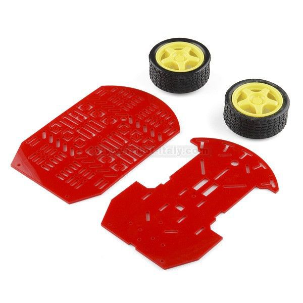
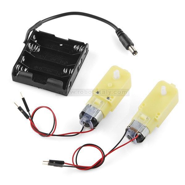
From Robot-Italy i get the chassis from a kit for a 3 wheeled robot and the battery, a LiPo of 1300mAh
Chassis:
http://www.robot-italy.com/en/magician-chassis-kit…
Batery:
http://www.robot-italy.com/en/fullpower-batteria-l…
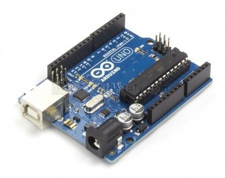
You can buy the Arduino form both stores, in Robot-Italy have the official version (23€) and in DX have the Chinese version (10€), in not gonna open a debate but i used both and they just work fine:
http://www.robot-italy.com/en/arduino-uno-r3.html
http://www.dx.com/p/uno-r3-development-board-micro…
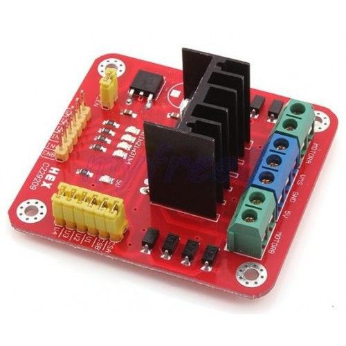
The last two thing left are the IMU sensor and the motor driver, both bought from DX:
Motor driver:
http://www.dx.com/p/l298n-stepper-motor-driver-con…
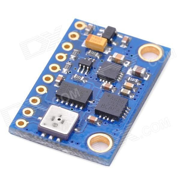
IMU sensor:
http://www.dx.com/p/gy-80-bmp085-9-axis-magnetic-a…
Making a price summary:
Arduino UNO ——————–> 10-20 €
IMU sensor ——————–> 15 €
Motor driver ——————–> 4 €
Chassis ——————–> 19 €
Battery ——————–> 10 €
______________________________________
TOTAL : 58-68 €
I used materials as cheap if i could but you can use whatever you have, i saw people using servo motors and stepper motors with a good result. This motor driver maybe is much bigger than the needed one, with an L293 it can work, you can make your own chassis and use other type of sensors.
Step 2: Phisics
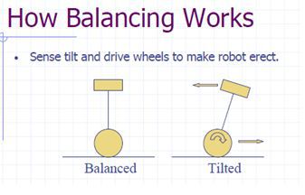
The physics for this robot are simple, the robot stand in two points lined, the wheel, and i tends to fall and lose his verticality, the movement of the wheel in the direction of the falling rises the robot for recover the vertical position.
A Segway-type vehicle is a classic inverted pendulum control problem that is solvable in two degrees of freedom for the simplest models. The vehicle attempts to correct for an induced lean angle by moving forward or backwards, and the goal is to return itself to vertical. Or at least not fall over.
For that objective we have two things to do, in one hand we have to measure the angle of inclination (Roll) that have the vehicle, and in the other hand we have to control the motors for going forward or backwards to make that angle 0, maintaining his verticality.
Angle Measurement:
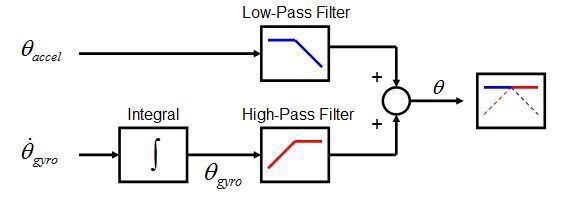
For measure the angle we have two sensors, accelerometer and gyroscope, both have his advantages and disadvantages. The accelerometer can measure the force of the gravity, and with that information we can obtain the angle of the robot, the problem of the accelerometer is that it can also measure the rest of the forces the vehicle is someted, so it has lot of error and noise. The gyroscope measure the angular velocity, so if we integrate this measure we can obtain the angle the robot is moved, the problem of this measure is that is not perfect and the integration has a deviation, that means that in short time the measure is so good, but for long time terms the angle will deviate much form the real angle.
Those problems can be resolved be the combination of both sensors, that’s called sensor fusion, and there are a lot of methods to combine it. In this project i try two of them: Kalman Filter, and complementary filter.
- The Kalman filter is an algorithm very extended in robotics, and offers a good result with low computational cost. There is a library for arduino that implements this method, but if you want to learn more about that method or implement it by yourself look at this page.
- The Complementary filter is a combination of two or more filters that combines the information from different sources and gets the best value you want. It can be implement in only one line of code .For more information visit this page.
angle = A * (angle + gyro * dt) + (1 – A) * accel;
where A is normally equals to 0.98.
First i tried to use Kalman filter but i don’t obtain good results, my angle was calculated with a little delay and it affect the control. The Kalman filter has three variables you can change based on the parameter of your sensor, and varying this you can obtain better result, i tried to change that values, but i don’t get better results so i decided to implement the complementary filter, so much easier and it have less computational cost. The complementary filter works fine for me.
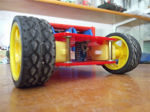
Step 3: Chasis
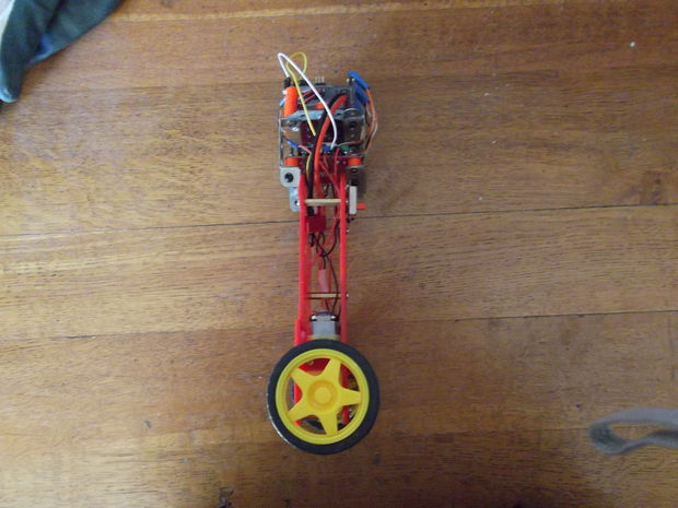
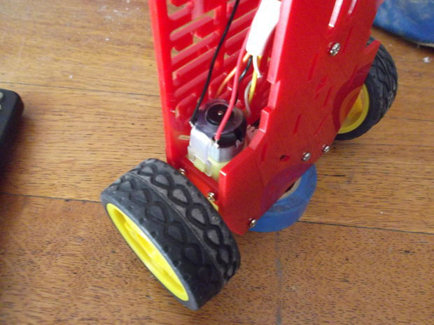
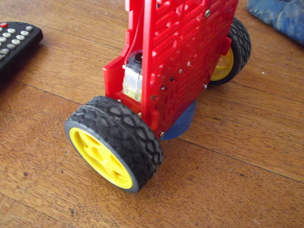
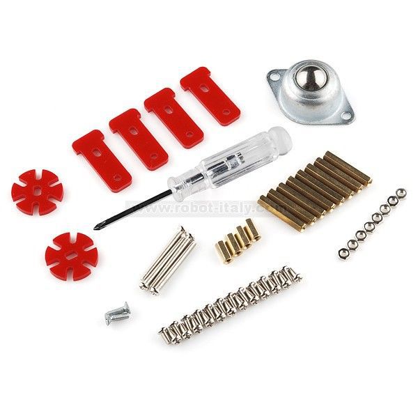
For create the main structure of the robot i used the kit previously mentioned, this kit contains a simple plastic chassis with some nuts and screws, two wheels with two motors, one battery socket, one caster wheel, and even 2 little wheels for encoders. The last time i checked the price was 19€.
Tip: If you like to make your own chassis with wood, aluminium, or other materials and if you have old DC motors and wheels you can save some money.
This kit is prepared to make a 3 wheel vehicle but we gonna change the plans a little to adapt it to our project.
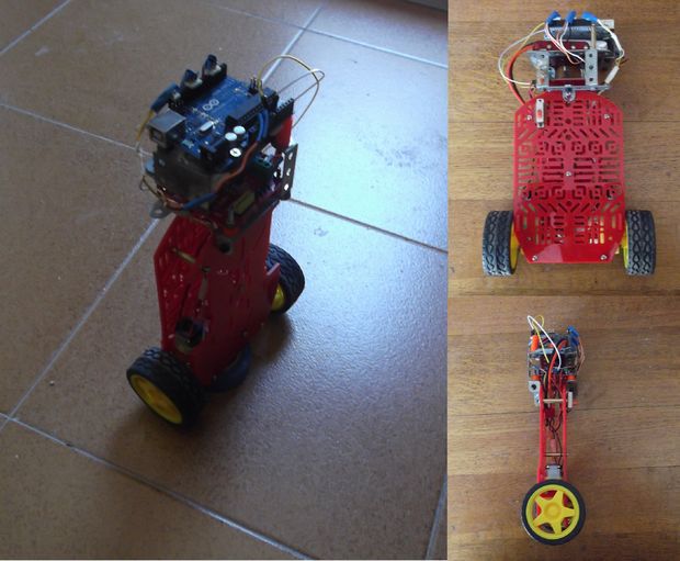
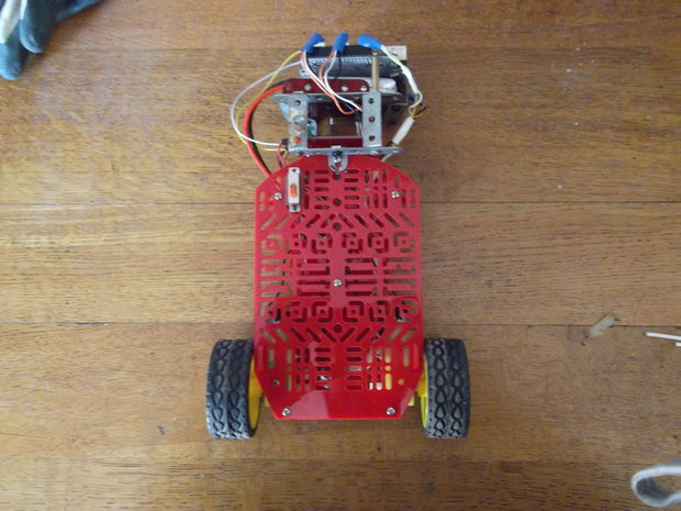
From the kit there are part i don’t use, like the caster wheel, two motor fastenings and some nuts and screws. I put the two motor in the lower part of the structure and closed it with the two grat plastic parts, keeping it together with the screws.
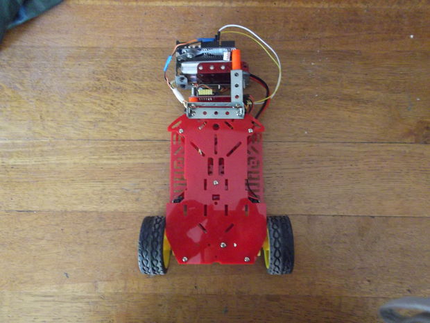
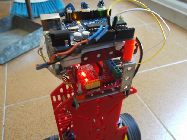
The electronics and the battery creates a tower in the upper part of the structure, i used Meccano to build the tower where the PCBs and the battery were located, but you can use other materials, like plastic, wood metal, or even only tape surrounding everywhere, like a gigant ball of tape.
And Voila! chassis done, not so difficult for the moment, let’s see next step.
Tip: When you build your robot you have to try to put the mass center the higher you can, putting heavy things in the upper part of the robot, like batteries. Remember that the more height of the center of mass the more stability the robot will have.
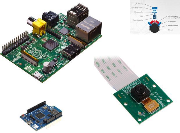
Step 4: Electronics
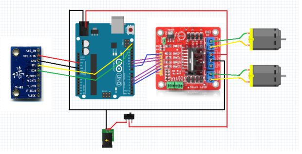
The electronics we are going to use in the project are simply three, an arduino UNO (you can use whatever arduino you have, doesn’t matter if isn’t arduino UNO), a motor driver, in this case a L298, and finally an IMU.
We use a commercial motor driver based on the chip L298, maybe much powerful that we need for these motors but i have it and it works fine. If you want to make you own DC motor driver you can use some transistors and make a H-bridge or use a L293, cheap and easy to use, there is an instructable where you can find information how to do it.
For the IMU i used the cheapest 10DOF (10 Degrees Of Freedom) i find, the chinese GY-80 with 3-axis accelerometer, 3-axis gyroscope, magnetometer, barometer and temperature sensors. We use only accelerometer and gyro so you can save money buying another IMU, like the MPU-6050, a 6DOF IMU for only 3.63€!!!!, or accelerometer and gyro for separate.
The IMU is connected to the arduino using I2C bus (If you want to lerarn more about I2C look this instructable), so we need 2 wires for communication (SDA and SCL) and 2 wires for power, it use 3.3V so we need 3.3V wire and GND.
The motor driver take power directly form the battery so don’t have to connect arduino’s power to it (i mean the 5V form the arduino), but we need 6 wires to control it, 3 for each motor, one for send the PWM signal for control the motor velocity, and for indicate the direction we want the motor to spin.
Tip: Try to position the IMU sensor (or accelerometer) in the line of the axis of the motors because if you locate the IMU far form this you can obtain much error in the accelerometer measure, remember that it measure linear acceleration, if you locate it to a distance R from the axis when the robot falls form vertical the acceleration of the accelerometer is the gravity plus R*dAngle/dt that means that it introduce an error in the measurement.
Step 5: Code
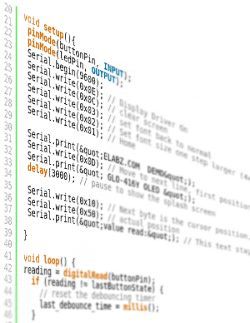
I’m not going to explain every single line of code for the project (i commented the code, if you download it i think u will have no problems to understand it), but i’m gonna show you how i organize it.
The code has 4 files: one the main code, a second one for the motors, the third is for the PID, and the last one is for the sensor code.
In the main code first i initialize the entire robot: pins, sensors, communications, … Then i calculate the error of the sensors. This part it’s very important because in this part we take the initial angle and we make it zero, it means that the sensor have an initial deviation, when we place the robot vertically the sensor don’t show that the angle is zero, instead send a deviation angle, this initial angle is used to subtract it from the posterior measurements of the sensors, to obtain the real angle. So when we initiate the robot we have to maintain it vertically until it starts to move the wheels.
The next part of code is the loop where we take the sensor values every 10 millisecond, that mean the frequency of sampling is 100Hz (you can use whatever frequency , but remember that very low and very high frequencies could not work), and we calculate the angle of the robot using, in this case, the complementary filter previously explained. We have the angle, now we can use that information to control our motors, this uses an intermediate PID, the simplest way to control things efficiently, there is an arduino library for the PID but is simple to implement it, you can code it in no more than 10-20 lines of code.
In order to use the accelerometer, in this case the ADXL345, we have to use its libraries. I used the next adafruit libraries: Adafruit_ADXL345 library and Adafruit_Sensor library.
And that’s all, simple code for simple robot, but it woks fine for me. You can implement so many more things if you want, like LCD screen, more sensors, better control, … That the magic of robots, you make one and improve it as much as you want.
Some of you have troubles using the code, i uploaded a single file with the entire project (Balacing_single_file).
Link to the google drive folder:

Step 6: Tests

I made a lot of test in the long way for this project, first i prove the motors: direction, velocity, … Then the sensors and the sensor fusion, that was a lot of time for find the right way to use it, i made a simple processing program (included in the code file) to show the values of the sensors graphically:
That help me to understand and to get the right form to take the real angle using Kalman or complementary filter.
At the end i prove the robot itself, the first prove was no as expected but it seems like we can achieve it
After some PID adjust and some code cleaning i reach the goal, maintain the robot vertically all the time, and even recover from pushing it with a little force. As you can see the robot walks with no control, drifting around without sense, but always vertical, that’s we wanted (for now).
Step 7: Improvements
There are some much improvements to do with this robot, this is the first step of many more:
- The first i want to implement is the position recovery, i don’t want my robot to walk around the room like a zombie although my cat like it, not me :D. For that we need encoders for measure the movement of the wheel and use it for bring the robot back to the initial position.
- Control the movement of the robot, forward, backward and turning , that is easy, the only thing we have to do is change the angle we want the robots stay then the gravity will do his work and the robot will move in the direction of the angle, then we put the angle to zero again and the robot stops. For turning we have to put some offset in the motor velocity, for turning right we subtract the offset to the velocity in right wheel and sum it to the velocity of the left wheel.
- Adding a WiFi shield to control it via internet.
- Implementation with Raspberry Pi to allow the robot to use a camera.
- Implementation of a camera and artificial vision for the robot.
- Use a ball instead of wheels, so hard, but we’ll try.