
Tag: Stepper Motor
4xiDraw V1 / A4 – Drawing Machine
4xiDraw V1 Series – Line-Up
iDraw Board V1 – MultiTools Machine – Design Concept
iDraw eX V2 – Drawing Machine – Design Concept
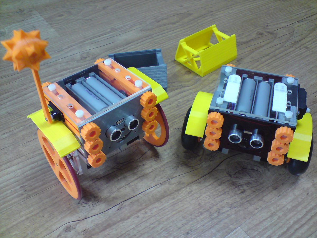
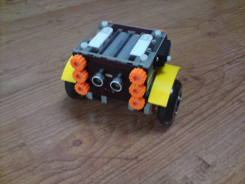
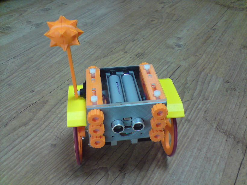
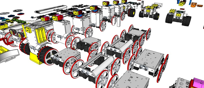
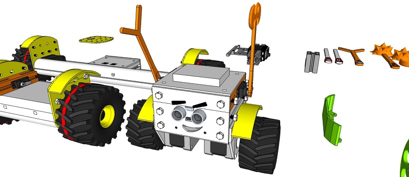
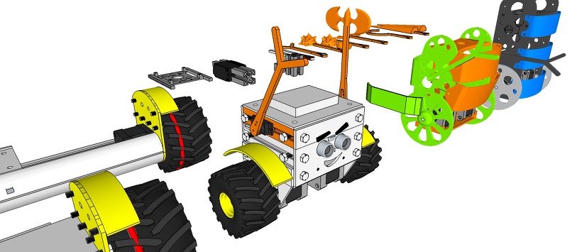
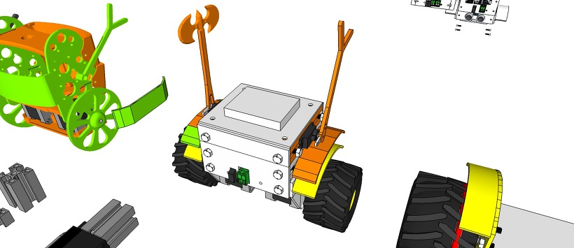
eX-Robot – ProfileBlock™ Robot Platform

[ Upload 20170424]
[ Upload design concept 20170418]
http://www.thingiverse.com/thing:2256715
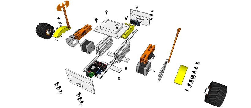
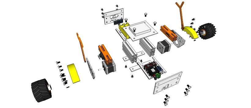
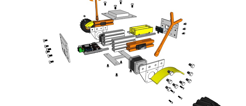
ProfileBlock – Balancing Robot – DIY Robots Platform
3D Design Tool: SketchUp Pro
ProfileBlock’s robots are built on top of an open source Arduino-based(with ESP8266, Raspberry Pi) platform.
Self Balancing Robot (eX-Robot, B-Robot, Roverbot, …
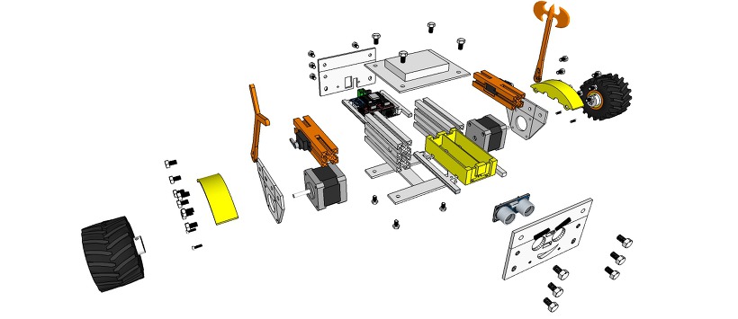
Hardware_____
Base Plate(Parts):
6 x ProfileBlock™ DF 2020 85mmAcrylic Plate (t = 3mm)1 x Top Plate1 x Bottom Plate
2 x Step Motor Mount Plate
1 x Front Plate
1 x Rear Plate3D Printing Parts
2 x Servo Mount ProfoleBlock
12 x Knob M5 Hexaheard
2 x Wheels 100mm or Inline Wheels 70mm(with 2 x Inline Wheels Hub)
2 x Tire Mudguards
1 x Stand1 x Battery Holder
Step Motor:
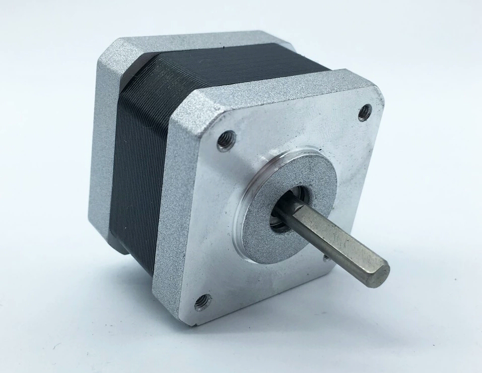
2 x Nema 17 Stepper Motor bipolar 4 leads 34mm 12V 1.3A 26Ncm(36.8oz.in) 3D printer motor 42SHD0001
2 x NEMA 17 – Phase: 4, Step Angle: 1.8 Deg/Step, Holding Torque: 2.6Kg.cm
Servo:
1 x Standard Servo or SG90 Metal Servo
1 x Standard Servo (Option) or SG90 Metal Servo
12 x M5 10mm Nylon Bolts
12 x M5 8mm Nylon Bolts
12 x M5 Nylon Nuts
8 x M3 8mm Bolts
4 x M3 10mm Bolts
4 x M3 15mm Bolts
8 x M3 Nuts
Electrical______
Control Board:
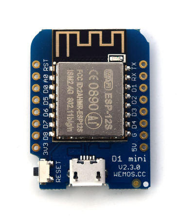
1 x ESP8266 Witty Cloud or WeMos (eX-Robot)
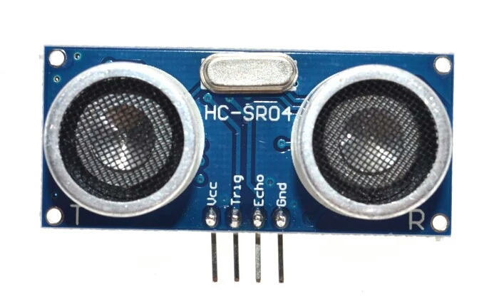
1 x HC-SR04 ultra sonic module
1 X MPU6050
2 x A4988 Step Motor Drive
1 x LM1117-5.0 5,0V 1A Regulator
1 x LM1117-3,3 3,3V 1A Regulator
6 x 100uF 25V Capacitor
4 x 0.1uF Capacitor
1 x 220KOhm Resistor
1 x 100KOhm Resistor
4 x 10KOhm Resistor
7 x 8P Female Pin Header Connector 2.54mm Pitch
3 x 4P Male Pin Header Connector 2.54mm Pitch
2 x 3P Male Pin Header Connector 2.54mm Pitch
3 x 2P Male Pin Header Connector 2.54mm Pitch
1 x 2EDGK 5.08mm 2P Plug-in terminal connectors set
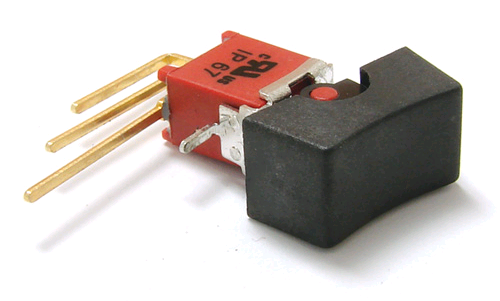
1 x Right Angle SPDT 4 Pin On-On I/O Boat Rocker Switch
1 x Interface Mother boardPower Requirements:8.4VDC
12 VDCBattery:2 x 18650 Litum Ion Battery = 7.2 VDC ~ 8.4 VDCSoftware:
1 x Interface Mother boardPower Requirements:8.4VDC
12 VDCBattery:2 x 18650 Litum Ion Battery = 7.2 VDC ~ 8.4 VDCSoftware:
ESP8266 WeMos D1 mini code: Coming soon…
WiFi UDP Control TouchOSC Layout file: Coming soon…
Arduino IDE (ESP8266 ESP-12E/F)Support SoftAP and StationSupport OTA (at Local network)Support mDNS (at Local network)
The open source ProfileBlock hardware and software is free and made with love. Please show your level of support with a voluntary donation.
Donate:
https://www.paypal.com/cgi-bin/webscr?cmd=_s-xclick&hosted_button_id=RDN7ZGAVFS5UE

Your Arduino Balancing Robot (YABR)
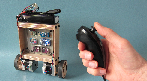
Your Arduino Balancing Robot (YABR) is a self-balancing robot that you can build yourself as a school project or as a fun project with your kids. It might look simple but there is a lot that you can learn from building this self-balancing robot.
In contrast to most self-balancing robots, this one uses stepper motors instead of regular DC motors. The main reason is that stepper motors are precise and have no performance loss when the battery voltage drops. One pulse is always an exact amount of motion. Regular DC motors can have mechanical friction and electric resistance differences. This can cause performance differences. As a result the robot will not move in a straight line.
The total cost to build this robot is approximately $80 if you use the hardware list below. This includes a battery, Nunchuck, charger, stepper motors, etc.
The Arduino program that you can download for free is 100% self-written and not based on any other software. The code is well commented and clearly explained. This makes it possible to further develop the code for your own purpose.
If you encounter any problems during the build or setup please check the  Q&A page first. Most questions are already answered in detail.
Step 1 – Software
First download the complete YMFC-AL software package:
Step 2 – Hardware
To build this robot you need hardware. I made the following list for convenience purpose alone. You are free to get your own hardware from different sources. But this is the hardware that I used/ordered:
- 1 x Arduino pro mini clone
- 1 x FTDI USB to TTL programmer for the Arduino pro mini
- 1 x Arduino Uno clone
- 1 x MPU-6050 gyro and accelerometer
- 2 x 2.4G wireless serial transceiver module
- 2 x 35mm Stepper motor
- 2 x Geeetech StepStick DRV8825
- 1 x Wired nunchuck controller for Wii
- 1 x Mini DC 7~28V to DC 5V step-down converter
- 1 x 11.1V 2200mAh 30C Li-polymer Battery
- 1 x B3AC 2S/3S Lipo balance charger
If the 35mm stepper motors are out of stock. You could also use these stepper motors. Please note that these are 42mm in stead of 35mm. So you have to modify the frame.
Most of the following parts can be found in your local electronics store. But in case you don’t have an electronics store nearby I will put links here:
- 1 x 1/4W Ceramic metal film resistors set (600 PCS)
- 1 x Glass fiber prototyping PCB
- 1 x 3-Pin toggle switch (5-Pack)
And finally you need an old inner tube and two sheets of plywood. I used 2.5mm and 12.5mm sheets.
Step 3 – Tools
And of course you need some simple tools like a soldering iron, screwdrivers, a fretsaw, compact drill, etc.
Step 4 – The build
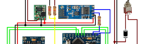
Watch the YABR hardware build video and build the robot according to the video and the schematic that is included in the complete software package.
| Building the YABR balancing robot. |
Detailed pictures of my own YABR balancing robot can be found in the media section of this project page.
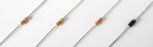
4.1 The diode and resistors
The resistor R1 on the schematic is needed for uploading a program to the Arduino. The TXD output of the transceiver is forced high or low. As a result the FTDI programmer cannot change this output anymore and you will get an upload error. By adding this resistor the FTDI programmer can change the voltage on the RX-pin of the Arduino despite the state the transceiver output and the program is uploaded without any problems.
The other two resistors (R2 and R3) form a voltage divider. Meaning that the 12.6 volt of the battery minus the 0.6 volt voltage drop over the diode is divided by 2.5. Resulting in a 4.8 volt on the analog input when the battery fully charged. In the main program this analog input will be used to protect the battery. This is because lipo batteries can be damaged when the voltage drops below 3 volt per cell.
The diode D1 protects all the electronics against reversed polarity. So when you accidentally reverse the connections of the battery the components won’t go up in smoke.
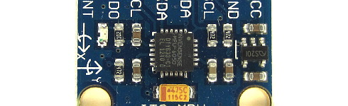
4.2 The MPU-6050 gyro/accelerometer
The only gyro / accelerometer that is supported by the YABR software is the MPU-6050. This is because the self-level feature requires an accelerometer and a gyro as I explain in these two videos:
| MPU-6050 6dof IMU tutorial for auto-leveling quadcopters – Part 1 |
| MPU-6050 6dof IMU tutorial for auto-leveling quadcopters – Part 2 |
The orientation of the gyro is important. Make sure to mount the gyro in the exact same orientation as shown on this picture. Otherwise the YABR software cannot calculate the correct angle and the robot will not work.
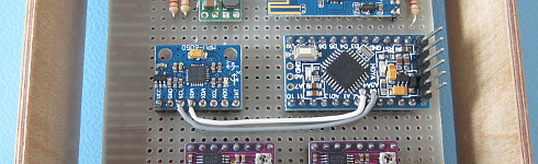
4.3 Hardware test
Please note that you are soldering the wires on the back side of the PCB. The schematic is drawn facing the components from the front. So everything is mirrored and you need to double check all the connections before you connect any power to the PCB.
With everything in place it’s time to connect the FTDI programmer to the Arduino pro mini. Don’t connect the battery yet. If the LED’s don’t lit up there is a short circuit in the wiring and you need to disconnect the FTDI programmer as soon as possible. Normally the Arduino pro mini is already programmed with the blink sketch so the LED on the Arduino should start to flash.
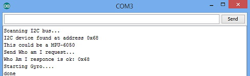
To check if the gyro is connected correctly and to check the balancing point of the robot you need to upload the “hardware-check” program that you can find in the software package that you downloaded earlier.

Test the balancing angle of the robot and fix it in that position on a stand as I showed in the video. Upload the “hardware-check” program, open the serial monitor and set the baud rate to 9600.
After uploading the program, open the serial monitor and set the baud rate to 9600.
The program will check if there is any I2C device is connected and if this is a MPU-6050. If everything is working as expected the program will output several raw gyro values on the screen. These are just examples and your values may be different. Note down the balance value that you see in the serial output. You will need it later in the main program.
4.4 Limit the motor current
Next thing on the to do list is to set the stepper controllers to the correct drive current. If the motor current is set to high the stepper controllers will heat up and they might get damaged.
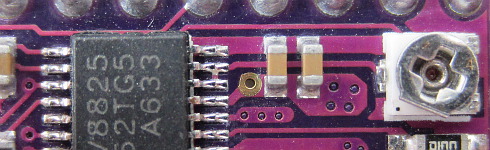
First set the potentiometer at the same position as shown in the picture below. Now always be careful when connecting the lipo battery for the first time. A short circuit can cause high currents, heat, sparks, and burns.
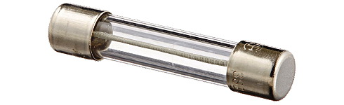
A good alternative is to use a small DC fuse like the one below. This fuse will blow if the wiring on the back side of the pcb holds a short circuit.
The easiest and safest way to set the correct current and to check if the wiring is correctly connected is by measuring the current in the power supply wires with a bench power supply. The power supply is limited to 500milli amps. This is an extra safety feature. If there is a short circuit the power supply will limit the current to 500 milli amps and the wiring will be fine.
First connect one motor. With the potentiometer it’s possible to set the current between 100 and 150mA. This is more than enough to get good performance. Do the same with the other stepper controller.
If you don’t have the possibility to measure the current just set the potentiometer in this position and feel if the stepper driver doesn’t get to hot. But it’s always best to measure the current.
3.5 The remote control
If you open the Nunchuck you can note the wire colors that are connected to the various pins as you can see on the schematic. The Nunchuck works on 3.3V and you can use the 3.3V output of the Arduino Uno to power the Nunchuck.
The 5V output can be used for the transceiver. Again, connect the wires as shown on the schematic to get it to work.
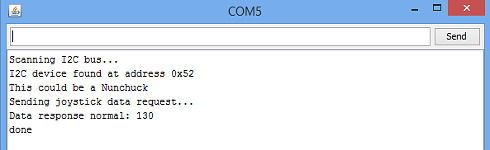
To check if the Nunchuck is connected correctly you need to upload the “hardware-check” program that you can find in the software package that you downloaded earlier. After uploading the program, open the serial monitor and set the baud rate to 9600.
The program will check if there is any I2C device is connected and if this is a Nunchuck. If everything is working as expected the program will output several raw joystick values on the screen.
Step 5 – Upload the software
And finally you can upload the YABR-remote program to the Arduino Uno and the YABR-robot program to the Arduino pro mini.
The YABR-remote program does not need any modification. In the robot program you need to change the accelerometer calibration value to the value that was shown by the hardware test program when the robot was in it’s balancing position.
To start the robot you need to power up the remote. Lay the robot on it’s back and switch on the power. The LED will blink indicating that the gyro is calibrating. When the blinking stops you can slowly lift the robot and it will automatically start to balance itself.
And basically that’s it. You can now control the robot with the Nunchuck.

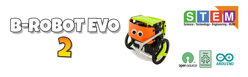
B-Robot EVO 2 KIT (Plug and Play Robot version)
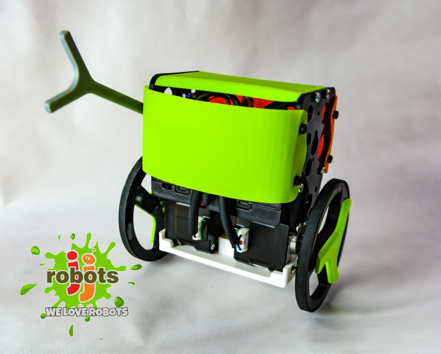
JJrobots´s B-ROBOT EVO 2 Kit. Created to simplify the set up and integration of all the different devices involved in this project.
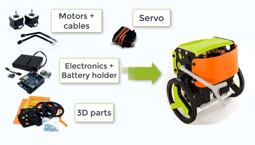
This COMPLETE VERSION includes all the electronic and hardware components required to create the B-Robot. You just need to assemble everything (optional 3D parts)
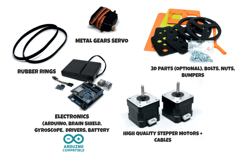
What you get when you buy this KIT:
- jjRobots Brain Shield
- Arduino Leonardo (CLONE) + USB cable (already programmed)
- 2x High Quality NEMA17 stepper motors +14 cms cables (pair)
- 2x Stepper motor driver
- IMU (gyro+accelerometers) + custom cable
- Powerful servo: Metal gears (you will need an arm to fight and raise your B-robot…)
- 6x AA Battery case with ON/OFF Switch (batteries not included)
- Bolts+nuts needed to set everything up
- Pair of nylon bumpers (14×5 cms)
- Double side tape, googly eyes…
- Optional: 3D printed parts
NEW: control your B-robot using the JJrobots FREE APP! (Android devices) or the Roverbot APP (for iOS phones. not official)
new B-ROBOT Evo 2 FEATURES:
-
- STEM education robot: perfect introduction to a robot that solves the inverted pendulum problem. Modify the B-robot EVO 2 as much as you can (both the robot parts themselves or its code) while you have fun!
- Control it using your smartphone/tablet via the free jjRobots APP
- Google Blockly controllable!
- Perfect to have fun as you learn robotics (Take a look to the Robotics Challenges!)
- Now can use regular AA batteries (or a 3 cells LIPO battery)
- Two SERVO outputs (one used for the ARM). Both can be controlled from the jjRobots APP
- Easier to print and using less plastic
- PRO MODE can be activated from your smartphone/Tablet (increased agility and velocity)
- Increased WIFI range (up to 40 meters)
- Battery status
- “Tilt angle” displayed in real time on your smartphone screen
![]()


B-ROBOT Evo 2 Features:
- STEM education robot. In addition to being fun, the B-robot EVO 2 engage beginners and advanced students and incorporate many of the fundamental STEM concepts providing a learning platform that everyone enjoys
- Control it using your smartphone/tablet using the free jjRobots APP
- Google Blockly controllable
- Perfect have fun as you learn about robotics (Take a look to the Robotics Challenges!)
- Open Robot project: code and 3D design files are open and shared. You could personalise your robot as much as you want.
- DIY & Hackeable: BROBOT is not a closed final product, BROBOT is an open, modifiable and hackeable platform, perfect to learn and play as much as you want!
- Develop your own apps: You could modify the source code of BROBOT to perform new tasks but the communication protocol is also open so you can develop your own IOS, Android, PC remote apps to control your BROBOT!
- Learn: BROBOT is a JJROBOTS product and this mean that you will receive a well documented project (source code and external documentation). We want you know all that is happening inside your Robot! This is ideal for learning and teaching technology. We will provide very good documentation. How we are controlling the motors, how we read and integrate the information from gyros and accelerometers, how we are controlling de stability of the robot, how we communicate with the control apps, etc…
– Build with your kids, at school, for yourself… this is a unique gadget. A perfect STEM education robot
– This self balancing robot has a medium size, perfect to carry your own beer (or mineral water ;-))
– There is a community behind BROBOT so you will have a forum to ask questions, share your experiences, MODs/ Hacks and contact other users…
– You can use these self balancing robot parts to create more robots or gadgets, keep in mind all the devices used in a BROBOT are standard electronic devices with a lot of potential. In the JJROBOTS community we want to show you how! You are now buying a self balancing robot, you are buying your a versatile set of electronics and ancillary devices.
B-Robot EVO 2. Much more than a self balancing robot


![]()
REMOTELY CONTROL YOUR B-ROBOT EVO

Control and tune-up your B-robot from your own smartphone/ tablet using the Control APP (freely available on Google play).
Modify its PID robotic control in real time and see how that affects to its behaviour and performance.
The new version displays the battery status and robot´s tilt angle in real time. Control the two servo output just tapping on the screen.


![]()
HAVE FUN LEARNING ROBOTICS

Learn Robotics and have fun with the STEM Challenges!
How does this robot work? Can I adjust its behaviour? And modify it?
STEM education robot: In addition to being fun, the B-robot EVO 2 engage beginners and advanced students and incorporate many of the fundamental STEM concepts providing a learning platform that everyone enjoys
Bring a beverage can to the other side of the room not dropping it, race against other B-robots with different configurations and add-ons and understand what it is going on. The B-robot EVO 2 is a very versatile and fun STEM learning robot

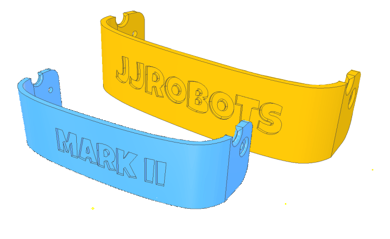
CUSTOMISE YOUR ROBOT!

Create your own bumpers and personalise your B-robot with the online customisation tool on Thingiverse
![]()
![]()


USEFUL LINKS


B-Robot EVO 2 Assembly guide

Better than a bunch of photos we have created an Assembly guide video. Some steps, like how to program the Arduino, controlling your robot or Troubleshooting are listed below. The interactive 3D model will help you to get a good idea about how the B-robot EVO looks.
Part list:
- jjRobots Brain Shield (or equivalent: schematic info here)
- Arduino Leonardo (CLONE) + USB cable (already programmed)
- 2x High Quality NEMA17 stepper motors +14 cms cables (pair)
- 2x Stepper motor driver
- IMU (gyro+accelerometers) + custom cable
- Optional: 3D printed parts (vibrant colours)
- Powerful servo: Metal gears (you will need an arm to fight and raise your B-robot…)
- 6x AA Battery case with ON/OFF Switch (batteries not included)
- Bolts+nuts needed to set everything up
- Pair of nylon bumpers (14×5 cms)
- Double side tape, googly eyes…
Have questions/ comments? Refer to the B-robot EVO community!
HOW TO:
UPLOAD the ARDUINO CODE to the ARDUINO LEONARDO
(skip this step if you got the Plug & Play B-robot EVO kit version. The Arduino is already programmed)
a) Install the Arduino IDE on your PC from (skip this step if you have the Arduino IDE already installed)
This B-robot code has been tested and developed on IDE version 1.6.5 and later versions. If you have a problem compiling the code, let us know
b) Download all the arduino files from GITHUB (https://github.com/jjrobots/B-ROBOT_EVO2/tree/master/Arduino/BROBOT_EVO2) or from here
Copy the files inside the BROBOT_EVO2 folder in your hard drive
c) Compile and send the code to the Arduino Leonardo
- Open your Arduino IDE
- Open the main code in /BROBOT_EVO2/BROBOT_EVO2-XX.ino
- Connect your Leonardo board with the USB to the PC
- Note: If this is the first time you connect a Leonardo board to your PC maybe you might need to install the driver.
- Select the board Leonardo (tools->board)
- Select the serial port that appears on the tools->Serial port
Send the code to the board (UPLOAD button: Arrow pointing to the RIGHT)

d) Done!
CONTROL YOUR B-ROBOT EVO 2:
Android users:
We have developed a FREE APP to control the Brobot (and future JJrobots) for your Android based Smartphone/Tablet:
It works sending UDP packets to the B-robot. It uses a simple layout with Throttle and Steering slicers and several buttons.
Steps to follow:
- Install the JJRobots control APP
- After turning the Brobot EVO ON, connect your smartphone/tablet to the B-robot EVO´s wifi network (remember, the WIFI´s password is 87654321)
- Launch the JJrobots control APP and play with your B-robot EVO!

Above: Screen capture of the JJrobots B-robot control APP (available for free in GOOGLE PLAY)
iOS users. App Store App or TouchOSC :
iOS B-robot control APP (thanks to Xuyen for this great contribution!)
It is quite straightforward to use. Just connect your iPhone/iPad to the B-robot EVO´s wifi (use the password “87654321“) and launch the App.
(thanks to Xuyen for this great contribution!)
iOS TouchOSC APP: Alternative way to control the B-robot EVO. Setup guide and files here
USEFUL LINKS:
Arduino CODE (latest version V.2.0) and the GITHUB REPOSITORY
B-robot Challenges (robotics, Academy)
B-robot alternative frames: Stealth version, Compact version (credits to s199)
B-robot EVO 2: 3D MODEL
TROUBLESHOOTING:
My B-robot is not responding to the command sent from my smartphone/tablet
Check you are connected to the JJROBOTS_XX netwrok using the correct password (by default: 87654321) and your device has not blocked the data traffic to the B-robot (stay always connected to the robot)

The IMU gets loose/ the i2C cable is too short
The gyroscope (IMU) is one of the most important element in this robot. It provides the current angle of the robot updating its value hundred times per second. The protocol used to send the data is quite sensitive to any electromagnetic interference so a very short cable is needed to connect the IMU and the Brain Shield. At the same time, vibrations create false angle measurements so we have to isolate the Brobot´s main frame vibrations from the IMU: that is the reason to use a double sided sticky pad to fix the IMU to the Brain Shield.
Place the IMU as indicated above: Close to the Brain Shield´s i2C connector. Bend the cable if needed. If you place the IMU as above, there should not be any lateral force pushing the IMU out of place
My B-robot lacks of power or fall without reason
Adjust the current delivered by the stepper motors drivers. Use a screwdriver and gently rotate the screws indicated on the photo below. Rotating 10º-30º is more than enough.
Clockwise rotation: increase the power delivered to the motors

A4988 STEPPER MOTOR DRIVERS output current potentiometer

My B-robot can not stand up by itself.
If everything is ok, the B-robot only needs a little bit of help from the servo to stand up by itself. Take a look to the video below. If your robot does not behave like in the video, adjust the stepper motor drivers output power (instructions above). Keep in mind that the bumpers have two functions here: protect the electronics+robot and help it to stand up easily.
Video Player
DEBUG MODE
There is a DEBUG MODE inside the B-robot CODE. This MODE will allow you the debug the behaviour of the robot if you are having issues. Please, refer to the B-robot community if you have problems or questions.
Look at the sketch line “#define DEBUG 0″ and change the 0 to 1…8 depending on what info you want to get. Take a look to the CODE below:
#if DEBUG==8
Serial.print(throttle);
Serial.print(” “);
Serial.print(steering);
Serial.print(” “);
Serial.println(mode);
#endif
//angle_adjusted_radians = angle_adjusted*GRAD2RAD;
#if DEBUG==1
Serial.println(angle_adjusted);
#endif
//Serial.print(“\t”);
mpu.resetFIFO(); // We always reset FIFO
// We calculate the estimated robot speed:
// Estimated_Speed = angular_velocity_of_stepper_motors(combined) – angular_velocity_of_robot(angle measured by IMU)
actual_robot_speed_Old = actual_robot_speed;
actual_robot_speed = (speed_M1 + speed_M2)/2; // Positive: forward
int16_t angular_velocity = (angle_adjusted-angle_adjusted_Old)*90.0; // 90 is an empirical extracted factor to adjust for real units
int16_t estimated_speed = -actual_robot_speed_Old – angular_velocity; // We use robot_speed(t-1) or (t-2) to compensate the delay
estimated_speed_filtered = estimated_speed_filtered*0.95 + (float)estimated_speed*0.05;
#if DEBUG==2
Serial.print(” “);
Serial.println(estimated_speed_filtered);
#endif
// SPEED CONTROL: This is a PI controller.
// input:user throttle, variable: estimated robot speed, output: target robot angle to get the desired speed
//target_angle = (target_angle + speedPControl(estimated_speed_filtered,throttle,Kp_thr))/2.0; // Some filtering : Average with previous output
//target_angle = target_angle*0.3 + speedPIControl(dt,estimated_speed_filtered,throttle,Kp_thr,Ki_thr)*0.7; // Some filtering
target_angle = speedPIControl(dt,estimated_speed_filtered,throttle,Kp_thr,Ki_thr);
target_angle = constrain(target_angle,-max_target_angle,max_target_angle); // limited output
#if DEBUG==3
Serial.print(” “);
Serial.println(estimated_speed_filtered);
Serial.print(” “);
Serial.println(target_angle);
#endif
#if DEBUG==10
Serial.print(angle_adjusted);
Serial.print(” “);
Serial.println(debugVariable);
#endif
#if DEBUG==6 //BATTERY STATUS
Serial.print(“B”);
Serial.println(battery);
Serial.print(” “);
#endif
#if DEBUG==7
Serial.print(distance_sensor);
Serial.print(” A”);
Serial.println(autonomous_mode_status);
USEFUL INFO: ARDUINO LEONARDO, IMU 6050 & STEPPER MOTOR DRIVER(A4988):
Arduino Leonardo:
MPU-6050 (gyro+accelerometers)
- MPU-6050 series info can be found here
- How to integrate it with any Arduino, here
- Schematic and connection info, here
Stepper motor driver A4988:
FAQ (frequently asked questions):
Why are you using Stepper motors?
There are several options for motors: DC, Brushless, Steppers… We choose stepper motors because they have enough torque, you could connect the wheels directly without gears that generate some backslash (this is a common problem in balancing robots), they have good bearings and you will be able to control the speed of the motors with accuracy. In standard sizes these motors are cheap (we use the same motors used on a regular 3D printers) and the drivers are cheap and easy to interface with Arduino too.
Why you use a Wifi connection?
Using a Wifi connection allow us to work with a lot of devices (Smartphones, Tablets, PCs…) Bluetooth devices are cheaper but their range is usually shorter. Old devices are not supported and you could not connect it to Internet easily. The Wifi module that we recommend, allow us to create an Access Point, so you don’t need to use an existing Wifi infrastructure (cheap Wifi modules don´t let you do this). You can connect your device directly to the Robot anywhere but if you prefer you can hack it and use your own infrastructure therefore controlling your robot (or whatever you have created) over the Internet from any remote place in the world! (Cool, isn´t it?)
Why BROBOT?
Self balancing robots are fun to see and play. A self balancing robot requires sensors and control algorithms. You will find all the HOWTO and technical documents which explains the “behind the scenes” in JJROBOTS. Learn electronics and robotics creating your own BROBOT from scratch!.
There are some commercial solutions to the balancing robot, but here we want to share knowledge and thoughts. You can use the BROBOT parts to create more robots or gadgets, keep in mind all the devices used in a BROBOT are standard devices/electronics with a lot of potential. In the JJROBOTS community we want to show you how! You are now buying a self balancing robot, your are buying your own electronic and ancillary devices!
Thinking about creating a GPS self guidance robot? a modified version of BROBOT is your robot!
How much payload could carry BROBOT?
BROBOT could easily carry your soft-drink cans. We have tested with 500g of payload with success. More weight makes the robot more unstable but this could be fun also, isn’t it?
Why use stepper motors for a balancing robot?
There are several options for motors, DC, Brushless, Steppers… We choose stepper motors because they have enough torque, you could connect the wheels directly without gears that generate some backslash, they have good bearings and you could control the speed of the motors very precisely. Also they are cheap and the drivers too…
Could I use rechargeable batteries of Lipo batteries?
Yes, you could use standard AA batteries (alkaline recommended), AA rechargeable batteries (e.g. NiMh) or you could optionally use a 3S Lipo battery. Run Lipo batteries at your own responsibility.
What is the runtime of BROBOT?
With rechargeable AA batteries (e.g. Ni-Mh 2100mAh) you could expect around half to an hour of runtime
Could BROBOT work without the wifi module?
Yes, BROBOT could work and keep its stability. But, of course you could not control it without the module.
Could I change the name of the Wifi network that BROBOT generate?
Yes, on the configuration sketch you could change the name and also some other internet configurations. You could also connect BROBOT with your existing Wifi network
Is this a project for an Arduino beginner?
Well, BROBOT is not an easy “beginner project”, but it has a lot of documentation so you have a platform to grow your skills. You could first mount your BROBOT following the instructions and it should work OK, then you could start understanding some parts of the code and finally writing your own pieces of code…
For example it could be easily (there are tutorials for this) to write your code so the robot automatically move the arm and spin itself if you don’t send a command in 10 seconds…
More advanced hacks: Convert to a totally autonomous robot with obstacle avoiding adding a SONAR, convert to a follow line robot, and so on…
Why BROBOT electronics are not so cheap?
We are a really small startup (2 persons in our free time) and now we could only run small batch of electronics. As yo know the price of electronics drops quickly in high volume productions but we are starting… If we sell many boards and we could run more volume productions we will drop the prices!!. JJROBOTS didn´t born to get money, our spirit is to sell “good products” to found our next projects and spread the robotics knowledge
Have fun!