Stepper Motor is a motor controlled by a series of electromagnetic coils. The center shaft has a series of magnets mounted on it, and the coils surrounding the shaft are alternately given current or not, creating magnetic fields which repulse or attract the magnets on the shaft, causing the motor to rotate.
This design allows for very precious control of the motor,There are two basic types of stepper motors, unipolar steppers and bipolar steppers .
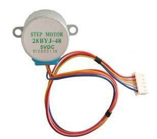
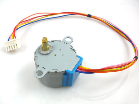
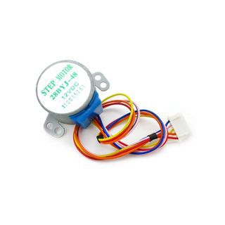
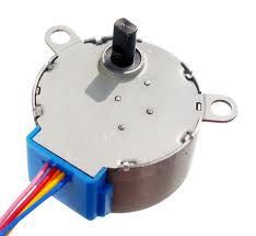
In This instructable , I will talk about an Unipolar Stepper Motor 28-BYJ48 .
The unipolar stepper motor has five or six wires and four coils (actually two coils divided by center connections on each coil). The center connections of the coils are tied together and used as the power connection. They are called unipolar steppers because power always comes in on this one pole.
Step 1: Specification , Motor Driver
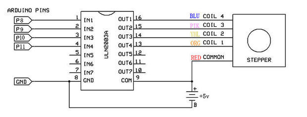
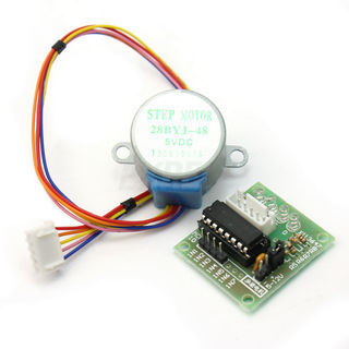
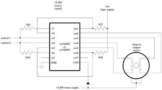
There are many Types of Drivers , L293 , ULN2003 , A3967SLB , And More ,
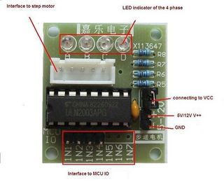
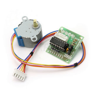
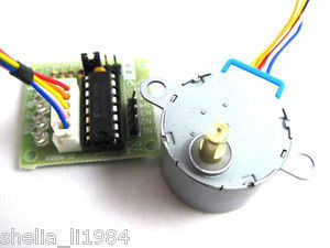
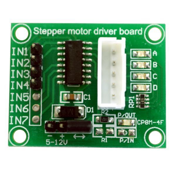
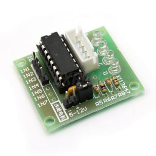
The 28-BYJ48 Even comes with Breakout using ULN2003 As a Motor driver chip .
Specification for this Motor ” And you can download datasheet from the attachment “Rated voltage : 5VDC
Number of Phase 4
Speed Variation Ratio 1/64
Stride Angle 5.625° /64
Frequency 100Hz
DC resistance 50Ω±7%(25℃)
Idle In-traction Frequency > 600Hz
Idle Out-traction Frequency > 1000Hz
In-traction Torque >34.3mN.m(120Hz)
Self-positioning Torque >34.3mN.m
Friction torque 600-1200 gf.cm
Pull in torque 300 gf.cm
Insulation grade Aand the schematics of This breakout shown like the Pictures on the attachment
Note that if you want to use L293 Instead of ULN2003 , You will need to leave Red wire No connection.
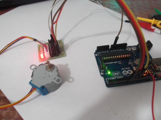
The Arduino IDE Support a Library for Stepper Motor , Very Easy to use , After Connect Motor with arduino You can Upload the Sketch on to the arduino .
But …
You must take something in consider :
This Motor has a Gear ratio of 64 , and Stride Angle 5.625° so this motor has a 4096 Steps .
steps = Number of steps in One Revolution * Gear ratio .
steps= (360°/5.625°)*64″Gear ratio” = 64 * 64 =4096 . this value will substitute it on The arduino Sketch
For adafruit Stepper Motor , the Stride Angle 7.5° and Gear ratio is 16 , So number of steps in 1 Revolution is :
steps in One Revolution = 360 / 7.5 = 48 .
steps= 48 * 16 = 768
That’s will be different depend on what motor you are using , So check The Datasheet for Your stepper Motor to calibrate this values
I designed this project for a 10-hour workshop for ChickTech.org whose goal is to introduce teenage women to STEM topics. The goals for this project were:
Easy to build.
Easy to program.
Did something interesting.
Low-cost so participants could take it home and continue to learn.
With those goals in mind, here were a couple of the design choices:
Arduino compatible for ease of programming.
4xAA battery power for cost and availability.
Stepper motors for accurate motion.
3D Printed for ease of customization.
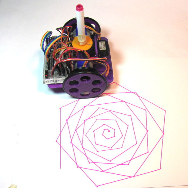
Pen plotting with Turtle graphics for interesting output.
Open Source so you could make one of your own!
Here is the robot that came closest to what I wanted to do: http://mirobot.io. I don’t have a laser cutter and shipping from England was prohibitive. I do have a 3D printer, so I guess you can see where this is going . . .
Don’t let the lack of a 3D printer deter you. You can locate local hobbyists willing to help you out at https://www.3dhubs.com/.
It took a lot of work, but I’m please with how it turned out. And, I learned quite a bit in the process. Let me know what you think!
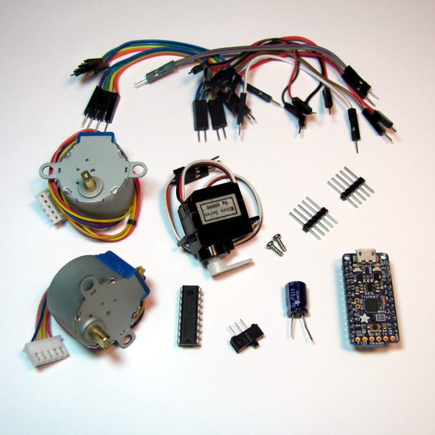
Step 1: Parts
There are a number of ways to power, drive, and control robots. You may have different parts on hand that will work, but these are the ones I’ve tried and found to work well:
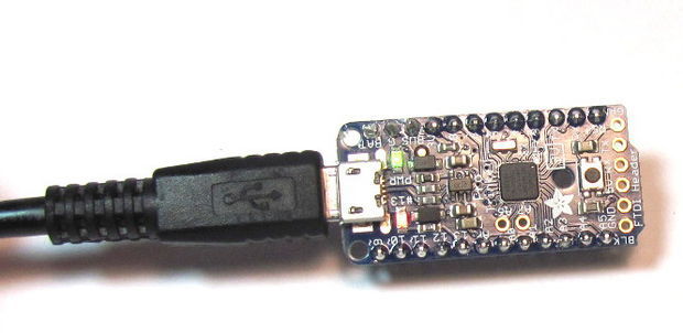
Before we get too far into construction, lets load the test firmware on to the microcontroller. The test program just draws for boxes so we can check for proper direction and dimension.
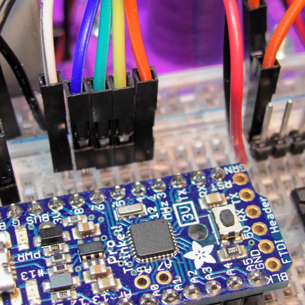
To talk to the Trinket Pro, you are going to need:
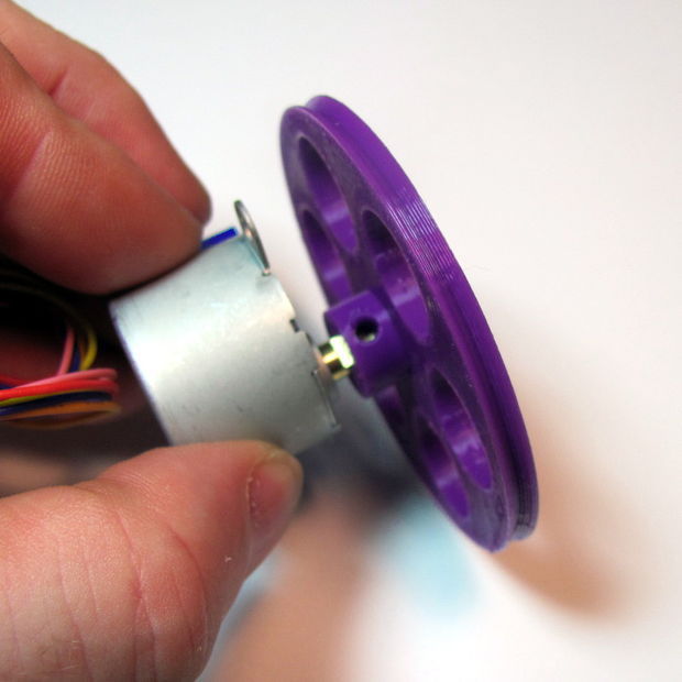
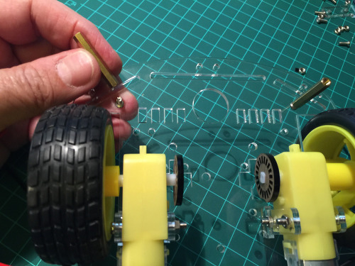
Place the o-ring around the rim of the wheel (Image 3 & 4).
Repeat for the other wheel.
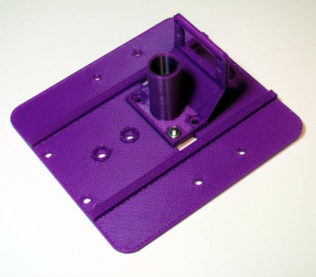
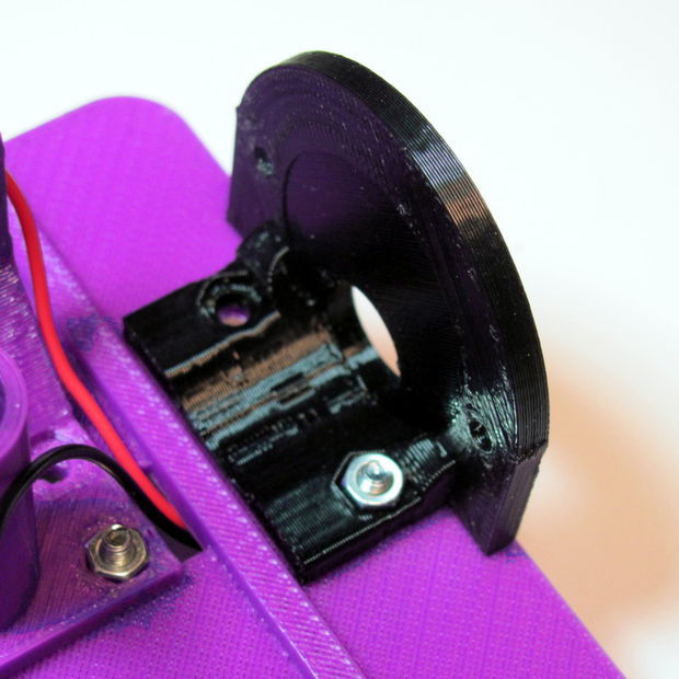
Step 5: Stepper Brackets
Insert a nut into the stepper bracket and attach them to the top of the chassis with a screw (Image 1).
Insert the stepper into the bracket and attach with screws and nuts.
Repeat for the other bracket.
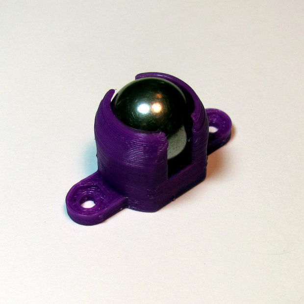
Step 6: Caster
Insert the ball bearing into the caster.
Do not force it in or it will break. Use a hair-drier or hot air gun to soften the material if needed.
Attach the caster to the bottom side of the chassis in front of the battery holder.
Step 7: Breadboard
Remove one of the power rails using a sharp knife, cutting through the bottom adhesive (Image 1).
Holding the breadboard over the chassis rails, mark where they intersect the edge (Image 2).
Using a straight edge (like the removed power rail), mark the lines and cut through the backing (Image 3).
Place the breadboard on the chassis with the rails touching the exposed adhesive (Image 4).
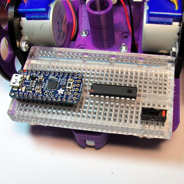
Step 8: Power
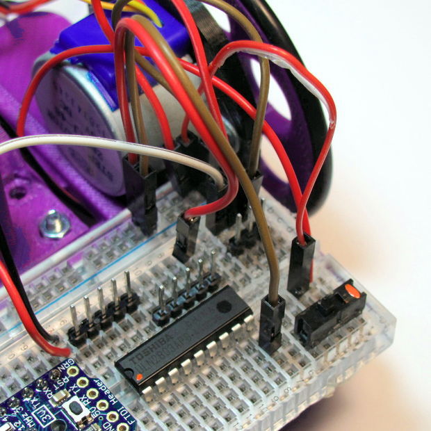
Place the microcontroller, darlington driver, and power switch on to the bread board (Image 1).
I’ve added orange dots for visibility to mark the following:
Pin 1 of the darlington driver.
The battery pin of the microtroller.
The power switch “on” position.
With the right-hand battery leads:
Connect the red line to the first pin of the power switch (Image 2).
Connect the black lead to an empty row between the microcontroller and the darlington chip (Image 2).
With the left-hand battery leads:
Connect the red line to the same row as the black lead of the other battery (Image 3).
Connect the black line to the negative rail of the breadboard (Image 3).
Connect power to the microcontroller:
Red jumper from positive rail to the battery pin (orange dot, Image 4).
Black jumper from the negative rail to the pin marked “G” (Image 4).
Install batteries and switch the power on. You should see the green and red lights of the controller come on (Image 5).
Troubleshooting: If the microcontroller lights do not come on, immediately turn the power off and troubleshoot:
Batteries installed in the correct orientation?
Double check battery leads positioning.
Double check switch leads positioning.
Use a multi-meter to check voltages of batteries.
Use multi-meter to check power rail voltages.
Step 9: Headers and Servo wiring
Male header pins allow us to connect the 5-pin servo JST connectors to power and the darlington driver (Image 1):
The first 5-pin header starts one row in front of the darlington driver.
The second servo header should then line up with the end of the darlington driver.
Before the wiring gets to complicated, lets get the servo wired up:
Add a 3-pin header for the servo on the right edge of the forward section of the breadboard( Image 2).
Add a red jumper from the center pin to the positive side of the power rail.
Add a black or brown jumper from the outer pin to the negative side of the power rail.
Add a colored jumper from the inner pin to Pin 8 of the microcontroller.
Install the servo horn with the shaft to the full clock-wise position and the arm extending to the right-side wheel (Image 3)
Install the servo in the pen holder using the servo’s screws (Image 3).
Connect the servo connector aligning the colors (Image 4).
Step 10: Stepper Control
Time to wire power for the darlington driver and steppers, which will be driven directly from the battery:
Connect a black or brown jumper from the lower right darlington pin to the negative side of the power rail (Image 1).
Connect a red jumper from the upper right darlington pin to the positive side of the power rail.
Connect a red jumper from the upper left pin header to the positive side of the power rail (Image 2).
Connect the left stepper connector to the left side pin header with the red lead on the right side (Image 3).
Connect the right stepper connector to the right side pin header with the read lead on the left side.
Note: The red lead of the stepper connector is the power and should match the red leads on the breadboard.
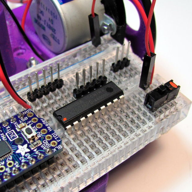
Step 11: Stepper Control (Continued)
Now we will connect the stepper signal wires from the microcontroller to the input side of the darlington driver:
Starting with Pin 6 of the microcontroller, connect the leads for four control jumpers for the left stepper motor (Image 1).
Match these jumpers to the input side of the darlington on the right. All colors should match with the exception of green, which matches the pink wire of the stepper (Image 2).
Starting with Pin 13 of the microcontroller, connect the leads for the four control jumpers for the right stepper motor (Image (3).
Match these jumpers to the input side of the darlington on the left. All colors should match with the exception of green, which matches the pink wire of the stepper (Image 3).
Step 12: Testing and Calibration
Hopefully you already uploaded the firmware in Step 2. If not, do it now.
The test firmware just draws a square repeatedly so we can check direction and accuracy.
Place your robot on a smooth, flat, open surface.
Turn the power on.
Watch your robot draw squares.
If you are not seeing lights on the microcontroller, go back and troublshoot power as in Step 8.
If your robot is not moving, double check the power connections to the darlington driver in Step 9.
If your robot is moving erratically, double check the pin connections for the microcontroller and darlington driver in Step 10.
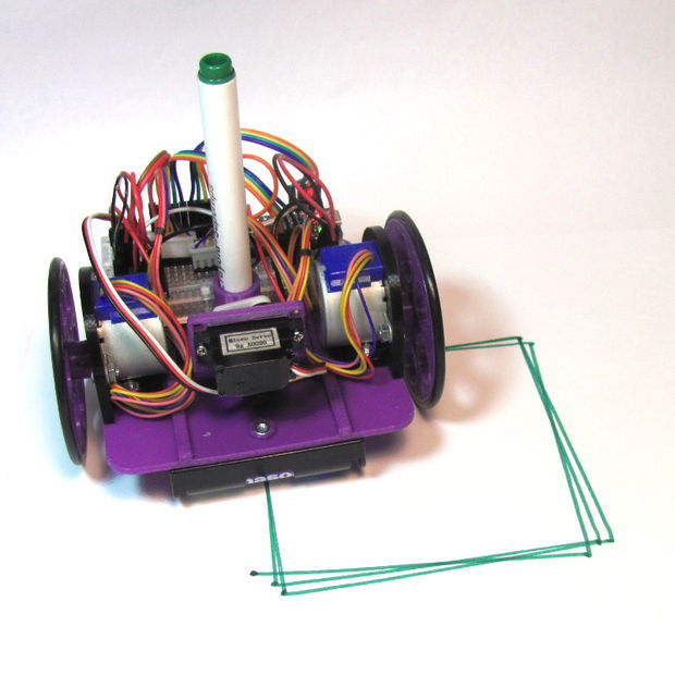
If your robot is moving in an approximate square, it is time to put some paper down and put a pen in it (Image 1).
Your calibration points are:
float wheel_dia=66.25;  // mm (increase = spiral out)
float wheel_base=112;   // mm (increase = spiral in)
int steps_rev=128;      // 128 for 16x gearbox, 512 for 64x gearbox
I started with a measured wheel diameter of 65 mm and you can see the boxes rotating inward (Image 2).
I increased the diameter to 67, and you can see it was rotating outward (Image 3).
I eventually arrived at a value of 66.25 mm (Image 4). You can see that there is still some inherent error due to gear lash and such. Close enough to do something interesting!
Step 13: Raising and lowering the pen
We’ve added a servo, but haven’t done anything with it. It allows you to raise and lower the pen so the robot can move without drawing.
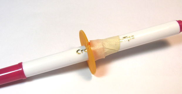
Place the pen collar on the pen (Image 1).
If it is loose, tape it in place.
Check that it will touch the paper when the servo arm is lowered.
Check that it will not touch the paper when raised (Image 2).
The servo angles can be adjusted either by removing the horn and re-positioning it, or through the software:
int PEN_DOWN = 170; // angle of servo when pen is down
int PEN_UP = 80;    // angle of servo when pen is up
The pen commands are:
penup();
pendown();
Step 14: Have Fun!
I hope you made is this far without too many curse words. Let me know what you struggled with so I can improve the instructions.
Now it is time to explore. If you look at the test sketch, you will see I have provided you some standard “Turtle” commands:
forward(distance);   // millimeters
backward(distance);
left(angle);         // degrees
right(angle);
penup();
pendown();
done();              // release stepper to save battery
Using these commands, you should be able to do just about anything, from drawing snow flakes or writing your name. If you need some help getting started, check out:
Could this robot be done with a regular Arduino? Yes! I went with the Trinket because of the low cost and small size. If you increase the chassis length, you can fit a regular Arduino on one side and the breadboard on the other (Image 1). It should work pin-for-pin with the test sketch, plus, you now can get to the serial console for debugging!
Could this robot be done with a Rasberry Pi? Yes! This was my first line of investigation because I wanted to program in Python, and be able to control it over the web. Like the full size Arduino above, you just place the Pi on one side, and the breadboard on the other (Image 2). Power becomes the primary concern because four AA is not going to cut it. You need to provide about 1A of current at a stable 5V, otherwise your WiFi module will stop communicating. I’ve found the Model A is much better on power consumption, but I’m still working out how to supply reliable power. If you figure it out, let me know!
ESP8266 modules are great low cost stand alone controllers with built in Wi-Fi. In this Instructable I will show you how you can control a Servo remotely over Wi-Fi with a Rotary Encoder. The Instructable is a similar but more advanced version of the “Arduino Nano and Visuino: Control Servo with Rotary Encoder” Instructable.
In the Instructable, I will use 2 NodeMCUmodules. One version 0.9, and the other 1.0. The NodeMCU are the easiest way to program and experiment with ESP8266controllers. This Instructable however can easily be done with other modules, and the Servo module can even use ESP-01 module as it needs only one GPIO pin to connect to the Servo.
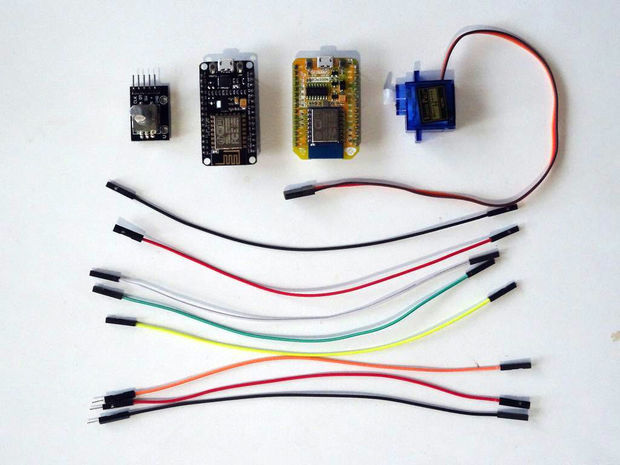
Step 1: Components
2 NodeMCU ESP8266 boards (I used both NodeMCU 0.9, and NodeMCU 1.0 versions, but any other combination, or even stand alone ESP-12 will work)
Step 2: Connect the Rotary Encouder to the first NodeMCU ESP8266 Module
Connect Ground(Black wire), Power(Red wire), Direction(Green wire), Clock(Yellow wire), and Switch wire(White wire) to the Rotary EncoderModule (Picture 1)
Connect the other end of the Ground wire(Black wire) to Ground pin of the ESP8266 NodeMCU module(Picture 2)
Connect the other end of the Power wire(Red wire) to the 3.3V power pin of the ESP8266 NodeMCU module(Picture 2)
Connect the Clock wire(Yellow wire) to Digital pin 2 of the ESP8266 NodeMCU module(Picture 3)
Connect the Direction wire(Green wire) to Digital pin 3 of the ESP8266 NodeMCU module(Picture 3)
Connect the Switch wire(White wire) to Digital pin 4 of the ESP8266 NodeMCU module(Picture 3)
Picture 4 shows where are the Ground, 3.3V Power, Digital 2, Digital 3, and Digital 4 pins of the NodeMCU 1.0
Step 3: Connect the Servo to the second NodeMCU ESP8266 Module
To simplify this Instructable, we will connect the Power from the NodeMCU to the Servo, In real projects, you will need to have a dedicated power supply for the servo! Please look at this Instructable to see how you can connect the Servo to external power.
Connect Ground(Black wire),Power(Red wire), and Control(Orange wire) to the Servo (Picture 1)
Connect the other end of the Power wire(Red wire) to the 5V(Called “Vin” in NodeMCU version 1.0) Power pin of the ESP8266 NodeMCU module (Picture 2)
Connect the other end of the Ground wire(Black wire) to the Ground pin of the ESP8266 NodeMCU module (Picture 2)
Connect the other end of the Control wire(Orange wire) to the Digital pin 2of the ESP8266 NodeMCU module (Picture 3)
Picture 4 shows where are the Ground, 5V(Vin) Power, and Digital 2 pins of the NodeMCU 0.9
Step 4: Start Visuino, and select the ESP8266 Board type
To start programming the Arduino, you will need to have the Arduino IDEinstalled from here: http://www.arduino.cc.
Make sure that you install 1.6.7 or higher, otherwise this Instructable will not work!
Click on the “Tools” button on the Arduino component (Picture 1) in Visuino
When the dialog appears, select “NodeMCU ESP-12” as shown on Picture 2
Step 5: In Visuino: Setup the module as Access Point
In the Object Inspector, expand the “Modules” property, then the “WiFi” sub property, then the “AccessPoint: sub property (Picture 1)
Set the value of the “SSID” sub property of the “AccessPoint”, to “ServoRemote” (Picture 1)
To make sure the Access Point will be on the 200.200.200.X subnet, we need to assign a fixed address.
In the Object Inspector, expand the “Config” sub property of the “AccessPoint” property (Picture 2)
Set the value of the “Enabled” sub property of the Config to “True” (Picture 2)
Set the value of the “IP” sub property to “200.200.200.100” (Picture 3)
Step 6: In Visuino: Add an UDP Socket for the communication
Next we need to add an UDP socket for the communication.
In the Object Inspector, click on the “…” button next to the value of the “Sockets” sub property of the “WiFi” property (Picture 1)
In the Sockets editor select “UDP Socket”, and then click on the “+” button (Picture 2)
In the Object Inspector, set the value “RemoteIPAddress” property to “200.200.200.200” (Picture 3) – this is the fixed IP address that we will assign to the other module later on
In the Object Inspector set the value of the “RemotePort” to “8888” (Picture 4)
Close the “Sockets” editor.
Step 7: In Visuino: Add and connect Rotary Encoder component
Type “rotar” in the Filter box of the Component Toolbox then select the “Rotary Encoder Sensor” component (Picture 1), and drop it in the design area
Connect the “Out” pin of the Digital[ 2 ] channel of the “NodeMCU ESP-12″component to the “Clock(A)” pin of the RotaryEncoderSensor1(Picture 2)
Connect the “Out” pin of the Digital[ 3 ] channel of the”NodeMCU ESP-12″
component to the “Direction(B)” pin of the RotaryEncoderSensor1(Picture 3)
Step 8: In Visuino: Add and connect Up/Down Counter component
We need a counter to count the Up/Down rotations from 0 to 100, and we need to set in in the middle/neutral 50:
Type “count” in the Filter box of the Component Toolbox then select the “Up/Down Counter” component (Picture 1), and drop it in the design area
In the Object Inspector set the value of the InitialValue property to 50(Picture 2)
In the Object Inspector expand the Counter’s Min property
In the Object Inspector set the value of the RollOver sub property to False(Picture 3)
In the Object Inspector set the
value of theValue sub property to 0 (Picture 3)
In the Object Inspector expand the Counter’s Max property(Picture 5)
In the Object Inspector set the
value of theRollOver sub property to False(Picture 5)
In the Object Inspector set the value of the Value sub property to 100(Picture 6)
Step 9: In Visuino: Connect the Up/Down Counter component
Connect the “Down” pin of the RotaryEncoderSensor1 component to the “Down” pin of the UpDownCounter1 component (Picture 1)
Connect the “Up” pin of the RotaryEncoderSensor1 component to the “Up” pin of the UpDownCounter1 component (Picture 2)
Connect the “Out” pin of the” Digital[ 4 ]” channel of the “NodeMCU ESP-12” component to the “Reset” pin of the UpDownCounter1 (Picture 3)
The Rotary encoder module switch that I have does not have pull up resistor. The ESP8266 however has built-in optional pull-up resistors for the pins. To enable the pull-up resistor for the Digital pin 4:
In the Object Inspector expand the “Digital” property, then the “Digital[ 4 ]” sub property (Picture 4)
In the Object Inspector set the value of the IsPullUp sub property to True(Picture 4)
Step 10: In Visuino: Add and connect Integer To Analog component
The servo needs analog value in the range between 0 and 1.0, so we need to convert the count to Analog and multiply it by 0.01 to convert the 0 to 100 range into Analog 0 to 1.0:
Type “To Analo” in the Filter box of the Component Toolbox then select the “Integer To Analog” component (Picture 1), and drop it in the design area
In the Object Inspector set the Scale property to 0.01 (Picture 2) . This will convert the counter values from the integer range of 0 to 100, to the analog range of 0.0 to 1.0.
Connect the “Out” pin of the UpDownCounter1 to the “In” pin of the IntegerToAnalog1 component (Picture 3)
Step 11: In Visuino: Add and Make Structure component, and add Analog channel to it
We need to send the analog value over the UDP. To do that we will make a structure with analog value and will send it over the UDP socket.
Type “make” in the Filter box of the Component Toolbox then select the “Make Structure” component (Picture 1), and drop it in the design area
Click on the “Tools” button (Picture 2) to open the “Elements” editor (Picture 3)
In the “Elements” editor select the “Analog” element, and then clickon the “+” button (Picture 3) to add an Analog element (Picture 4)
Close the “Elements” editor.
Step 12: In Visuino: Connect the Make Structure component
Connect the “Out” pin of the MakeStructure1 component to the “In” pin of the “Modules.WiFi.Sockets.UDPSocket1” of the “NodeMCU ESP-12” component (Picture 3)
Connect the the “In” pin of the “Elements.Analog1” element of the MakeStructure1 component to the “Out” pin of the IntegerToAnalog1component (Picture 3)
Step 13: Generate, Compile, and Upload the ESP8266 code for the Rotary Encoder Module
In Visuino, Press F9 or click on the button shown on Picture 1 to generate the Arduino code, and open the Arduino IDE
Connect the first NodeMCU module (The one with the Rotary Encoder) with USB cable to the computer
Select the board type and serial port as I have shown you in this Inctructable
Make sure you have installed the latest staging version of the ESP support! The stable release does not have some of the latest features, and you will have errors when you try to compile!
In the Arduino IDE, click on the Upload button, to compile and upload the code (Picture 2)
Step 14: In Visuino: Select the ESP8266 Board type, and configure it to connect to the Access Point
Now lets program the Servo module.
Start new project.
Click on the “Tools” button on the Arduino component, and when the dialog appears, select “NodeMCU ESP-12” as you did in Step 4 for the Rotary Encoder module
Next we need to configure the module to connect to the Access Point of the Thermometer module, and use a fixed IP Address of 200.200.200.200
In the Object Inspector, expand the “Modules” property, then the “WiFi” sub property, then the “AccessPoints” sub property, and click on the “…” button next to its value (Picture 1)
In the “AccessPoins” editor, select “WiFi Access Point”, and then click on the “+” button to add the access point (Picture 2)
In the Object Inspector, set the value of the “SSID” property to “ServoRemote” (Picture 3)
In the Object Inspector, expand the “Config” property, and set the value of the “Enabled” sub property to “True” (Picture 4)
In the Object Inspector, set the value of the “IP” sub property to “200.200.200.200” (Picture 5)
Step 15: In Visuino: Add an UDP Socket for the communication
Next we need to add an UDP socket for the communication.
In the Object Inspector, click on the “…” button next to the value of the Sockets sub property of the WiFi (Picture 1)
In the Sockets editor select “UDP Socket”, and then click on the “+” button (Picture 2)
In the Object Inspector, set the value “RemoteIPAddress” property to “200.200.200.200” (Picture 3)
In the Object Inspector set the value of the “Port” to “8888” (Picture 4)
Step 16: In Visuino: Add Split Structure component, and add Analog channel to it
The Remote Control module sends the servo position in binary floating point form as a packet. We need to decode it properly. For this we need a “Split Structure” component with “Analog” element in it.
Type “struct” in the Filter box of the Component Toolbox then select the “Split Structure” component (Picture 1), and drop it in the design area
Click on the “Tools” button (Picture 2) to open the Elements editor (Picture 3)
In the “Elements” editor select the “Analog” element, and then click on the “+” button (Picture 3) to add an Analog element (Picture 4)
Close the Elements editor.
Step 17: In Visuino: Add and connect Servo component
Type “servo” in the Filter box of the Component Toolbox then select the “Servo” component (Picture 1), and drop it in the design area
Connect the “Out” pin of the Servo1 component to the “Digital” input pin of Digital[ 2 ] channel of the Arduino component (Picture 2)
Connect the “In” pin of the Servo1 component (Picture 3) to the “Out” pin of the “Elements.Analog1” of the SplitStructure1 component (Picture 4)
Step 18: Generate, Compile, and Upload the ESP8266 code for the Servo
In Visuino, Press F9 or click on the button shown on Picture 1 to generate the Arduino code, and open the Arduino IDE
Connect the second NodeMCU module (The one with the Servo) with USB cable to the computer
Select the board type and serial port as I have shown you in this Inctructable
In the Arduino IDE, click on the Upload button, to compile and upload the code (Picture 2)
Step 19: And play…
Congratulations! You have completed the project.
Picture 1 shows the connected and powered up project.
If you rotate the Rotary Encoder back and forth, the Servo will move in the same direction, as you can see in the video. If you press the Rotary Encoder shaft down, the Servo will move to neutral center position.
On Picture 2 you can see the complete Visuino diagram for the Rotary Encoder Remote Control module.
On Picture 3 you can see the complete Visuino diagram for the Servo module.
이 프로젝트의 아이디어는 상기 프로세서로 라즈베리 파이를 사용하여 인터넷을 통해 완전히 제어 로봇을 생성하는 것이다. 로봇은 HTML로 작성된 웹 페이지에 의해 직접 제어 턴에있는 쉘 스크립트 작성 저수준의 명령을 사용하여 제어된다. 우리는 예를 들면 파이썬 같은 고급 언어를 사용하는 사실은, 로봇이 페이지 (인터넷 속도가 느린 경우에도)에 의해 수신 된 명령에 빠르게 반응하도록 야기된다.
아래 링크에서는 어떻게 완성 된 프로젝트를 볼 수 있습니다
이 프로젝트는 두 부분으로 분할하고, 배울 것 1 부에서한다 :
설치 및 GPIO가 RPI를 제어하는 라이브러리 WiringPi를 사용
는 H-Bridge를 사용하여 제어 모터
웹 서버의 RPI 변형
인터넷을 통해 상기 로봇을 제어하기 위해 HTML (자바 스크립트)에 페이지를 만들기
더 나아가 로봇이 현실 세계의 “비전”을 가지고 있는지 확인하기 위해, 당신은 당신이 배울이 튜토리얼의 두 번째 부분에 갈 수 있습니다 :
물어와 비디오 스트림을 생성하는 방법
설치 및 라이브러리 ServoBlaster를 사용하는 방법
서보 모터를 제어하고, 카메라의 수직 및 수평 위치 (WFP / 틸트기구) 메커니즘을 구축하는 방법
인터넷을 통해 카메라의 위치를 제어하기 위하여 HTML 페이지를 작성
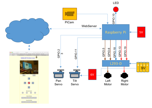
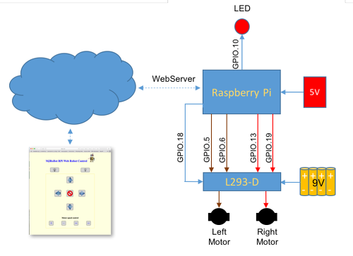
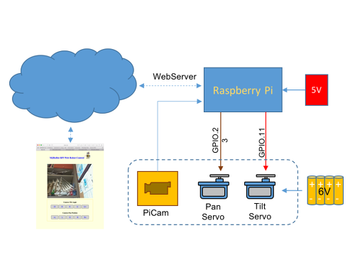
블록 다이어그램은 아래 날개 프로젝트의 두 부분에 대한 일반적인 생각을 보여줍니다
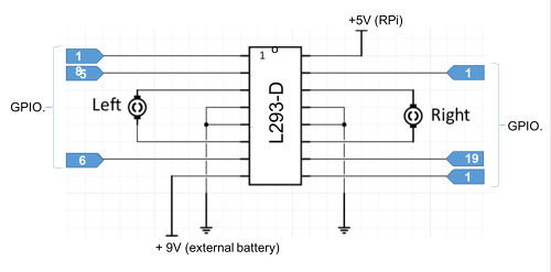
부 : 인터넷을 통해 조명 및 모터 제어
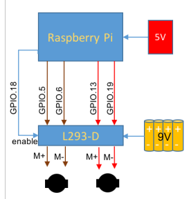
RPI는 웹 서버로 정의하고 HTML 페이지로부터 명령을 수신한다. 이러한 명령은 RPI 로봇 (방향과 속도)의 모터를 제어 일으키는 개의 GPIO의 상태를 변경 및 / 떨어져 LED에 (시뮬레이션 디지털 제어 시스템을 더)한다. 당신이 볼 수 있듯이, 로봇은 실제로 만약 IoT 프로젝트의 특별한 경우이다. 당신은 실제로 당신이 원하는 것을 제어 할 수 있으며,이 튜토리얼은 새로운 아이디어가 미래에 구현 될위한 출발점이 될하기위한 것입니다.
아래의 그림, 우리는이 첫 번째 부분에서 개발되는의 개요에서 :
자료의 목록
라즈베리 파이 모델 2 또는 3
H 브리지 L293-D
DC 모터 (2 배)
드라이버 9V 배터리
RPI에 배터리 5V
LED와 30 옴의 저항
브레드 보드 및 전선
아크릴 엔진 / 전자 제품에 대한 지원 (키트, CD를, 등을 할 수 있습니다)
도서관 WIRINGPI의 설치
WiringPi는 C로 작성된 라이브러리가 GPIO가의 RPI에 직접 액세스하는 데 사용됩니다. 매우 쉽게 쓸 수 있으며 크게 ( “embebeda 시스템”) RPI 및 전자 관련된 모든 프로젝트를 단순화합니다.
라이브러리 WiringPi는 “GPIO”프로그램 및 GPIO 핀을 구성 할 수 있습니다 (wiringpi.com/the-gpio-utility)라는 유틸리티가 포함되어 있습니다. 당신은 읽기 및 / 또는 쉘 스크립트와 같은 명령의 RPI의 핀에 직접 작성하는 유틸리티를 사용할 수 있습니다. 당신은 GPIO 쉘 스크립트에 명령 정수를 사용하여 프로그램을 작성할 수 있습니다.
WiringPi를 설치하려면 :
git clone git://git.drogon.net/wiringPi
cd wiringPi
./build
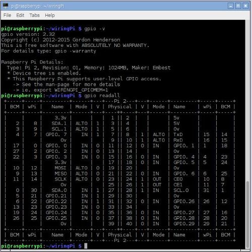
유틸리티의 화면 버전을 표시하려면 다음 명령을 사용합니다 :
gpio -v
일반적으로 액세스 모든 핀을 읽고 그 모드를 상호 참조 표를 작성하는 다른 포맷 (wiringPi, BCM_GPIO 핀 및 물리적)의 핀의 상태가 “GPIO의 ReadAll 메쏘드를”명령어를 사용할 수있는 테이블을 제시 현재 값을 표시합니다. 이 명령은 RPI와 파이에 적합한 인쇄도 소나무의 버전 / 모델을 감지합니다.
gpio readall
모니터 화면 아래 위의 두 명령의 항목의 결과를 나타낸다.
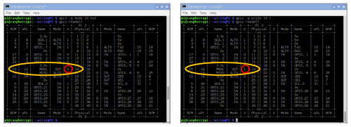
예를 들면, 출력으로서 BCM_GPIO 방식을 사용하여 하나의 GPIO를 설정하는 명령을 사용하는 것 :
gpio mode -g 10 out
가능 GPIO 핀이 정의 모드가되면, 당신은 동일한의 논리 상태를 정의 할 수 있습니다. 예에서, 핀은 논리 하이 상태로 이동한다 :
gpio write -g 10 1
그 양극과 GND 사이에 330ohm 저항을 부가 LED GPIO.10 핀의 음극을 설치 테스트합니다. 확실히 모든 것이 작동하는지 확인하기 위해 몇 가지 검사를 수행합니다.
출력 또는 입력으로 핀을 설정할 수있는 것 외에도 PWM 형식의 출력으로서 그 중 일부를 설정할 수있다. 이것은 물리적 핀 12 GPIO.18의 경우이다.
핀을 설정하려면 :
gpio -g mode 18 pwm
또는
gpio mode 1 pwm 참고 : ( “1”) GPIO.18에 WPI ID입니다
PWM 값을 설정합니다 :
gpio pwm 1 XXX 참고 : [XXX 0 사이의 값입니다 -> 1023]
예. :
gpio pwm 1 512 참고 : (50 % 듀티 cicle)
이 핀 particularmante의 구성을 제거하려면 :
gpio unexport 1
모든 핀 구성을 제거하려면 :
gpio unexportall
라즈베리 PI 및 LIBRARY WIRINGPI WITH 제어 모터
이 시점에서, WiringPi 라이브러리가 설치되어 있고 당신은 당신의 RPI의 모니터에 명령 줄에서 직접 GPIO를 제어 할 수 있습니다. 다음 단계는 모터를 제어하기위한 로직을 생성하는 것이다. 이를 위해, 우리는 H-다리의 L-293-D를 사용합니다. 이 H- 브리지는 2 개의 모터를 제어 할 수 있고, 모터의 각각에 대해 입력 3 필수 :
왼쪽 엔진 : “활성화”; “모터 +”와 “모터 -”
모터 오른쪽 : “활성화”; “모터 +”와 “모터 -”
항목에서 두 엔진은 서로 연결되어 “사용”GPIO.18에 의해 제어된다. 이 핀은 속도 제어에 대한 책임이 있습니다. 만약, 속도를 제어하는 “1”로 핀을하게 할 필요가없는 경우, 예를 들어 (+ 5V에 연결).
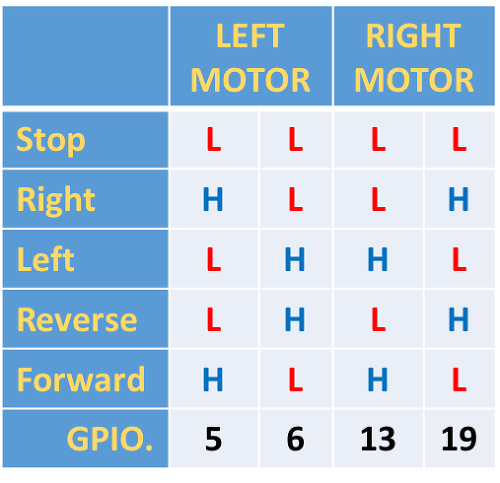
우리는 왼쪽 엔진이 “앞으로”이동하려는 경우, 우리는 + 모터 (M의 +)를 설정해야합니다, 협약 “1”과 모터 – (M-) “0”. 모터가 반대 방향으로 회전되도록 우리가 대향 할 것이다 : 엔진 + (M +)을 “0”으로 모터 – (M-) “1”이다. 실제로, 엔진의 방향을 정확하게 제어 입력을 정의하는 가장 좋은 방법은 동일한 조립하여 테스트하는 것이다.
우리는 항목의 다리에 개의 GPIO를 할당합니다 :
왼쪽 엔진 + : GPIO.5
왼쪽 모터 : GPIO.6
오른쪽 엔진 + : GPIO.13
오른쪽 엔진 – : GPIO.19
위의 가정에 기초하여, 논리는 GPIO를 테이블에 할당 될 수 수준 (표 화상을 참조)로 구축 할 수있다.
다음 단계는 엔진을 구동하기 위해 쉘 스크립트를 생성하는 것이다.
각 스크립트는 기본적으로 단순 텍스트 파일 형식이다. 텍스트 파일을 실행하려고하면, 운영 체제는 스크립트인지 아닌지를 결정하는 단서를 검색하며, 어떻게 적절하게 처리. 이 때문에, 당신이 알아야 할 몇 가지 지침이있다.
각 스크립트로 시작해야합니다 “#!/bin/bash”(해쉬 – 뱅 해킹}
각각의 새로운 라인은 새로운 명령입니다
주석 행은 #로 시작
명령은 ()에 의해 둘러싸여있다
운영체제 (쉘)은 텍스트 파일을 분석하면 스크립트의 첫 줄이 제작 될 때, 가장 직접적인 방법은 파일을 식별하기 #! / 빈이 / 떠들썩한 파티! 주석 행은 해시 (#)로 시작하지만 다음 OS를 강제 뱅 (!)와 쉘 경로를 추가하는 스크립트를 실행합니다.
예를 들어, “앞으로”이동합니다 모터를 제어하는 쉘 스크립트를 작성하고, 위의 테이블을 기반으로, 우리는 텍스트 편집기를 수행해야하고 I를 사용하고 당신을 위해 가장 적합한 편집기를 사용하여 (아래의 파일을 생성 이것에 대한 NANO) :
sudo nano forward.cgi
#!/bin/bash
gpio -g write 5 1
gpio -g write 6 0
gpio -g write 13 1
gpio -g write 19 0
스크립트가 생성되면, 우리는 당신에게 실행할 수있는 권한을 부여해야합니다 :
sudo chmod 755 forward.cgi
이제 스크립트를 실행합니다 :
sudo ./forward.cgi
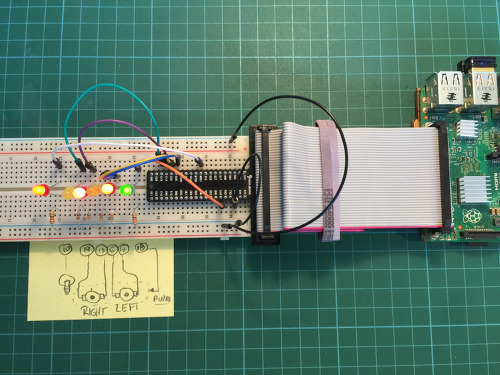
LED가 스크립트를 테스트하는 데 사용하고, 실제 엔진은 이후의 단계에서 첨가 될 것이다.
파일 확장자와 같은 것을 사용 .cgi로 참고. CGI는 “공용 게이트웨이 인터페이스”를 의미합니다. 이 웹 서버는 동적 웹 페이지를 생성하는 서버에 설치 실행 프로그램과 상호 작용하는 표준 방법입니다. 이러한 프로그램은 CGI하거나 CGI를 스크립트로 알려져 있습니다; 그들은 일반적으로 스크립팅 언어로 기술되지만, 임의의 프로그래밍 언어로 기록 될 수있다.
계속해서, 같은 아이디어는 상기 테이블의 다른 조합에 적용한다 :
sudo nano stop.cgi
#!/bin/bash
gpio -g write 5 0
gpio -g write 6 0
gpio -g write 13 0
gpio -g write 19 0
sudo nano reverse.cgi
#!/bin/bash
gpio -g write 5 0
gpio -g write 6 1
gpio -g write 13 0
gpio -g write 19 1
sudo nano left.cgi
#!/bin/bash
gpio -g write 5 0
gpio -g write 6 1
gpio -g write 13 1
gpio -g write 19 0
sudo nano right.cgi
#!/bin/bash
gpio -g write 5 1
gpio -g write 6 0
gpio -g write 13 0
gpio -g write 19 1
스크립트를 작성하면 forward.cgi으로 수행되었을 때, 당신은 그들에게 동일하게 실행할 수있는 권한을 부여해야합니다
sudo chmod 755 stop.cgi
sudo chmod 755 reverse.cgi
sudo chmod 755 left.cgi
sudo chmod 755 right.cgi
이제 모든 것이 작동하는지 확인하기 위해 몇 가지 테스트를 실행합니다 :
./forward.cgi
./left.cgi
./reverse.cgi
./right.cgi
./stop.cgi
좋은 방법은 자주 사용하는 프로그램에 대한 특정 디렉토리가 있고 “빈”을 호출하는 것입니다. 그래서, 우리는 프로젝트에서 사용하는 스크립트를 저장하려면, 우리는 예를 들어, 모든 실행 스크립트를 포함하는 CGI-빈 (또는 바이너리 파일)에 대해 디렉토리를 작성해야합니다.
우리가 우리의 웹 사이트가 위치하며 “VAR”에서 “WWW”디렉토리를 만들어 보자 그 아래, 스크립트 디렉토리 “CGI – bin에”
sudo mkdir /var/www
sudo mkdir /var/www/cgi-bin
이제, 우리는 새로운 디렉토리에있는 모든 파일을 이동 :
sudo mv /*.sgi /var/www/cgi-bin
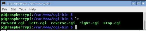
cd /var/www/cgi-bin
ls 명령을 사용하여 만든 파일을 볼 수 있습니다 :
/ 오프 LED 및 제어 엔진 속도 ON (선택 사항)
우리는 H 브리지 모터 제어를위한 oL293-D로 사용하기 때문에, 우리는 방향을 넘어, 우리는 또한 속도를 제어 할 것인지 여부를 결정해야합니다.
두 가지 가능성이 여기에 :
고정 속도 : 두 개의 저항으로 전압 분배기를 사용하여 연결 핀 1과 + 5V (최대 속도) 또는 다른 비례 값의 다리 (활성화) 9
나무 딸기 파이 GPIO.18에 연결 핀 1과 9 (PWM 출력)
우리는 우리가 조향 제어를 설정했던 것과 같은 방식으로 스크립트의 그룹을 생성합니다 :
sudo nano nospeed.cgi
#!/bin/bash
gpio pwm 1 0
sudo nano lowspeed.cgi
#!/bin/bash
gpio pwm 1 250
sudo nano regularspeed.cgi
#!/bin/bash
gpio pwm 1 512
sudo noano highspeed.cgi
#!/bin/bash
gpio pwm 1 1023
스크립트가 생성되면, 당신은 그들에게 실행할 수있는 권한을 부여해야합니다 :
sudo chmod 755 nospeed.cgi
sudo chmod 755 lowspeed.cgi
sudo chmod 755 regularspeed.cgi
sudo chmod 755 highspeed.cgi
자, 그냥 모든 것이 작동하는지 확인하기 위해 몇 가지 테스트를 실행합니다 :
./lowspeedcgi
./regularspeed.cgi
./highspeed.cgi
./nospeedcgi
테스트를 위해, 우리는 그의 섬광의 강도는 명령이 작동 볼 수 GPIO.18에 LED를 연결합니다.
마지막으로, 우리는 예를 들어, 나 램프를 끄려면 사용되는 디지털 출력을 제어하는 별도의 스크립트를 생성합니다. 우리는이에 대한 GPIO.10을 사용합니다 :
sudo nano llighton.cgi
#!/bin/bash
gpio -g write 10 1
sudo nano llightoff.cgi
#!/bin/bash
gpio -g write 10 0
sudo chmod 755 lighton.cgi
sudo chmod 755 lightoff.cgi
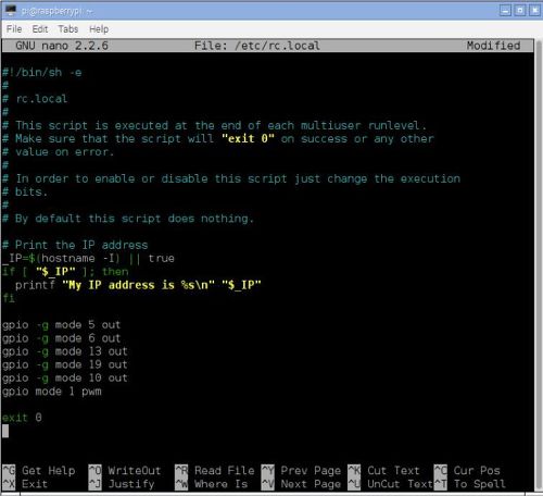
마지막 한가지 다른 단계로 이동하기 전에. 당신이 RPI를 다시 시작하면 개의 GPIO는 입력 기본 상태로 돌아갑니다. 그래서 우리는 모든 부팅의 시작 부분에 실행을 /etc/rc.local 스크립트를 변경해야합니다.
그냥 스크립트의 마지막 명령 (종료 0) 전에 GPIO가 모드 설정 명령을 포함합니다 :
sudo nano /etc/rc.local
…
gpio -g mode 5 out
gpio -g mode 6 out
gpio -g mode 13 out
gpio -g mode 19 out
gpio -g mode 10 out
gpio mode 1 pwm
exit 0
“출구 0″직전의 커맨드 라인으로서 PWM 명령을 갖는 것이 좋다.
RPI를 시작할 때마다 이제 영사 출력을 제어 할 준비가 될 것이다.
즐길 이제 시스템을 다시 부팅합니다
sudo reboot
설치하기 WEBSERVER
매우 가볍고 빠른 웹 서버입니다 lighttpd를 설치합니다 (예를 들어 대신 아파치 사용할 수 있습니다). 그 위키 페이지에 기재된 바와 같이 “이 Lighttpd 고성능 환경에 최적화 빠르고 유연한 보안 웹 서버가있다. 그것은 다른 웹 서버에 비해 낮은 메모리 풋 프린트를 가지고 있으며, 너무 CPU를로드 할주의하십시오.
이제이 Lighttpd 및 해당 구성 요소를 설치하자 :
sudo apt-get -y install lighttpd
sudo lighttpd-enable-mod cgi
sudo lighttpd-enable-mod fastcgi
기본적으로,이 Lighttpd 디렉토리에 index.html 페이지를 찾을 경우 : / var / www /에서 HTML을. index.html을이 폴더에 직접 저장할 수 있도록하자,이를 변경하자의 경우 : / var / www가. 이를 위해, 당신은이 Lighttpd 구성 파일을 편집해야합니다 :
sudo nano /etc/lighttpd/lighttpd.conf
변경:
server.document-root =“/var/www/html”
으로:
server.document-root =“/var/www”
이 변경 사항을 적용하기 위해 중지하고 웹 서버를 다시 시작해야합니다 :
sudo /etc/init.d/lighttpd stop
sudo /etc/init.d/lighttpd start
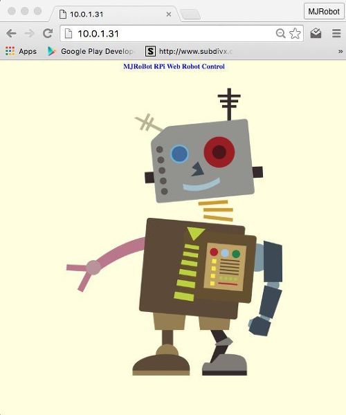
이때, 웹 서버가 실행되고 index.html 페이지는 단지 IP 어드레스를 입력 RPI,은 / var / www가, 우리는 브라우저로부터 액세스 할 수 있습니다.
우리는 테스트 목적으로 간단한 페이지를 작성합니다.
첫째, 우리는 페이지 이미지를 저장하는 디렉토리를 작성 :
mkdir /var/www/images
(시험, 난 이미 디렉토리 (/images/robot52.png)에 나에게 .PNG 파일을 보낸 있습니다 :
cd / var / www
sudo index.html nano
<html>
<head>
</head>
<style>
body {background-color: lightyellow}
h1 {color:blue}
</style>
<body>
<div style=”text-align:center”>
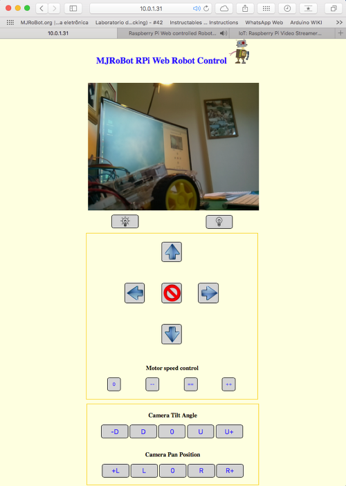
<h1>MJRoBot RPi Web Robot Control</h1>
<br><br>
<img src=”/images/robot52.png”>
</body>
</html>
페이지를 편집 완료 후, 저장 및 사용 권한을 변경 :
sudo chmod 755 index.html
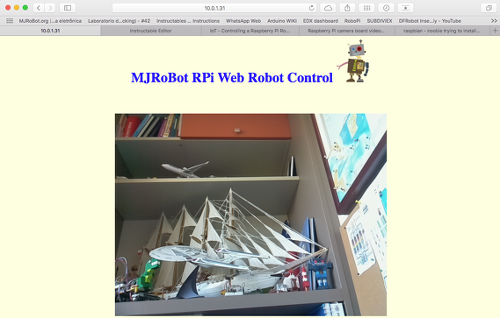
지금 내 경우 예를 들어, IP 주소 라즈베리 파이를 브라우저를 열고 입력 : 10.0.0.31을
최종 결과는 아래에 볼 수있다 :
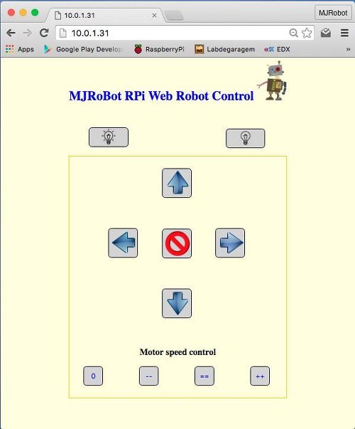
로봇을 제어하기 ONE PAGE의 HTML을 생성하기
의 우리의 웹 사이트를위한 심플한 디자인을 생각하자. 무엇을 할 수 명령?
lighton.cgi 및 lighoff.cgi : 두 개의 버튼은 ==> 스크립트로 작동 켜고 불을 끕니다
모터 제어 방향 다섯 버튼 ==> 스크립트로 작동합니다 forward.cgi, stop.cgi, left.cgi, right.cgi 및 reverse.cgi
모터 속도 제어를위한 네 개의 버튼 ==> escripts 작동합니다 : nospeed.cgi, lowspeed.cgi, regularspeed.cgi 및 highspeed.cgi
우리가 마지막 단계에서 생성 된 HTML의 index.html 파일을 사용하여, 우리는 자신의 스크립트 구현을위한 통화 기능을 설정 버튼이 포함됩니다.
버튼을 누를 때, 명령 “의 onclick = LIGHTON는 ()”은 “LIGHTON는 ()”함수를 호출하기 때문에 :
function lighton()
{
xmlhttp.open(“GET”,”cgi-bin/lighton.cgi”,true
xmlhttp.send();
}
LIGHTON () 함수가 호출되기 때문에 그리고, 스크립트가 lighton.cgi와 “짜잔는”LED가 켜집니다 실행됩니다.
동일한 절차가 다른 버튼을 사용한다. 외관을 구성하고 페이지를 작성하는 데 사용되는 다른 HTML 태그가있다.
HTML 소스 파일 (이전 단계에서 사용되는 LED의 구성의 테스트 페이지)에서 볼 수있다 :
HTML 페이지에 링크
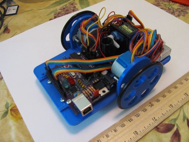
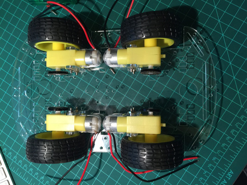
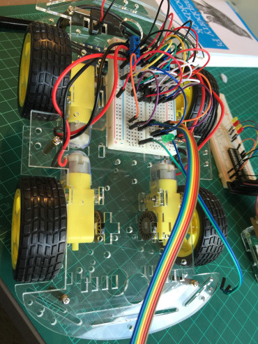
ROBOT BODY ASSEMBLY
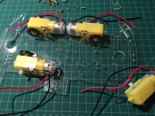
우선 플랫폼을 찾는 것입니다. 나는 4 DC 모터와 4WD 키트를하기로 결정했다. 이동성 분석은 4WD가 (코너링을 위해) 여기에서 생각하기 때문에 제어가 용이 아니라고하지 않습니다 실현, 우리는 완전한 로봇을 설정하지만, 실제 테스트는 나는 “코스터”를 추가하여 후륜을 사용 just’ll 전면에 ( “rolon”와 같은 탈취제 남아).
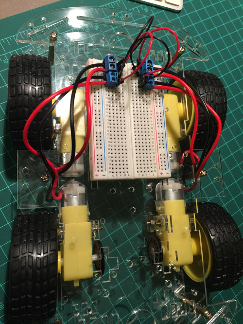
몸과 엔진이 제자리에 후에는, 브레드 보드를 포함 모터 연결하고 테스트하는 시간이다. 각각의 모터를 테스트하기 위해 외부 배터리를 사용합니다.
아래 그림과 같이 엔진은 H 브리지 D-L293에 의해 제어됩니다
이 시점에서, 당신은 또한 RPI의 GPIO가 시뮬레이션, 다리의 입력에 + 5V와 GND를 사용하여 모터를 제어, 테스트를 수행 할 수 있습니다.
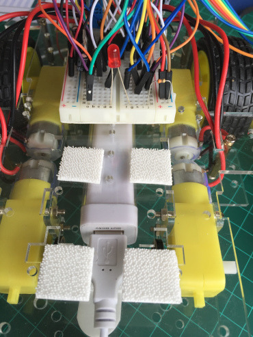
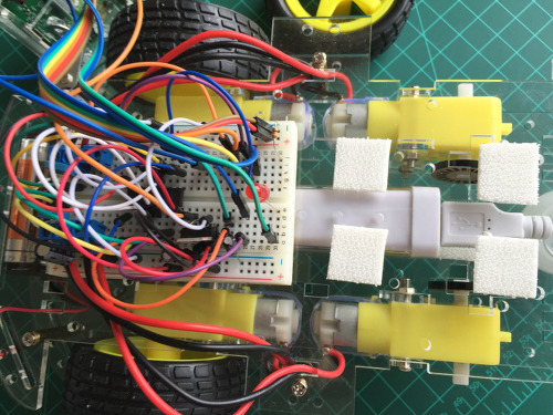
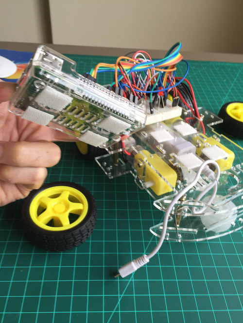
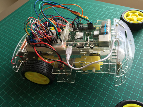
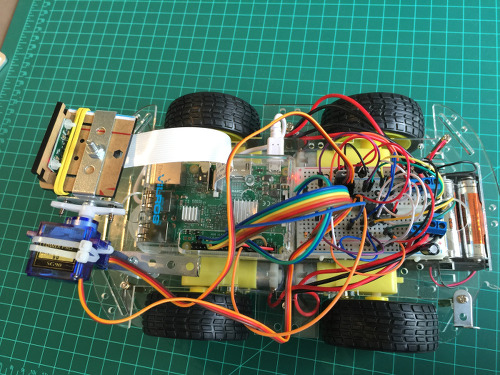
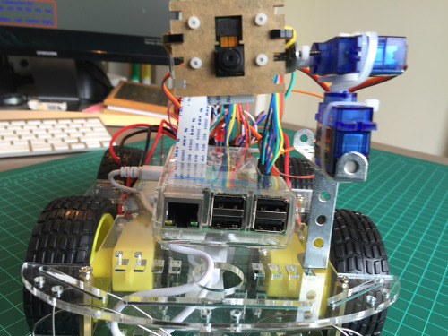
RPI 설치
모든 corretamante 작동되면, 그것은 라즈베리 파이를 추가하는 시간이다. 전체 회로는 다음과 같습니다 :
작은 섀시와 엔진 사이의 RPI 5V 배터리를 설치합니다. RPI는 상단에 있습니다.
은 RPI를 켜기 전에 모든 케이블 연결을 확인합니다.
이전의 모든 단계가 OK 인 경우에, 당신은 IP 주소 RPI를 사용하여 로봇을 제어 할 수 있습니다.
당신의 마음에 드는 웹 브라우저와 안전한 여행을 엽니 다!
이하, 로봇이 웹 페이지를 사용하여 테스트가 비디오 :
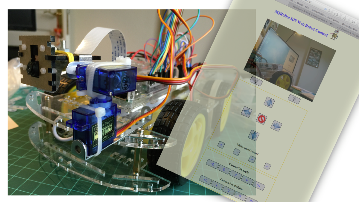
파트 2 : 인터넷 카메라의 비디오 스트리밍 및 원격 제어 (팬 / 틸트)
도입에서 설명하고있는 바와 같이, 로봇은 사물의 인터넷 사업을 개발하는 변명은 거의이다. 우리가 여기 짓을하면 거기에서, 우리는 거의 모든 것을 제어 할 수 있습니다 Internet.The를 통해 GPIO가 RPI를 제어하는 것입니다!
이 두 번째 부분에서, 우리는 고통을 탐구 비디오를 스트리밍하는 방법도 서보 모터를 사용하여 카메라의 위치를 제어하는 방법을 찾을 수 있습니다. 인터넷을 통해 카메라를 제어하는 것은 보안에 사용하기 위해 포함, 여러 용도를 가질 수 있습니다.
궁극적 인 목적은 상기 프로젝트의 두 부분을 결합 만이 인터넷을 통해 제어 할 수없는 로봇을 만들뿐만 아니라, 스트리밍 비디오를 전송하는 것이다.
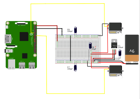
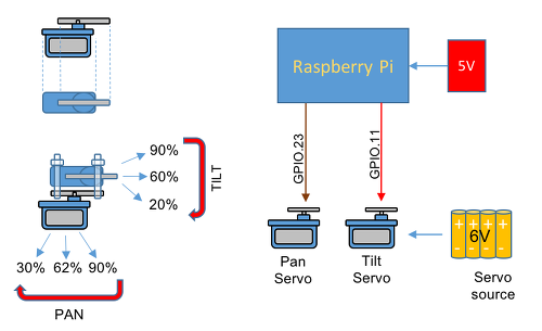
블록 다이어그램은이 프로젝트의 두 번째 부분의 개념을 도시한다.
RPI는 웹 서버로 프로그래밍 및 HTML 페이지로부터 명령을 수신한다. 이 명령은 위치는 서보 모터 (팬 / 틸트와 수평 / 수직)를 통해 파고, GPIO가 RPI를 제어합니다.
자료리스트
이전 재료의 목록, 우리는 고통과 두 개의 미니 서보 180도를 추가합니다. 그것은 Voltagen 6V 레귤레이터 (7806)는 엔진 전원 같은 이미 설치된 9V 배터리를 사용할 수있게하는 것이 필요하다.
스트리밍 비디오
튜토리얼을 기반으로 비디오 트리머 물기를 설치합니다 :
엘 모타 (업데이트 2014년 1월 19일)가 개발 라즈베리 파이 보드 카메라 비디오 스트리밍.
ISO 400, Video Stabilisation No, Exposure compensation 0
Exposure Mode ‘auto’, AWB Mode ‘auto’,
Image Effect ‘none’, Metering Mode ‘average’,
Colour Effect Enabled No with U = 128, V = 128
Rotation 0, hflip No, flip No
www-folder-path…: /opt/mjpg-streamer/www/
HTTP TCP port…..: 9000
username:password.: disabled
commands……….: enabled
Starting Camera
Encoder Buffer Size 81920
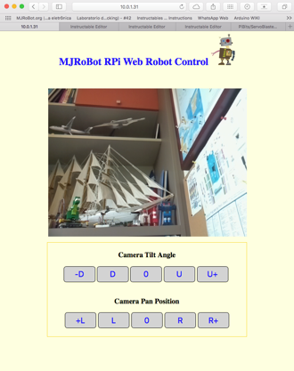
카메라가 작동되어야한다. 브라우저 및 유형으로 이동
http : // 당신의 IP 주소 : 9000 / stream.html
것과 같은 테스트 페이지 아래 (카메라에 의해 촬영 된 이미지) 표시됩니다.
참고 당신은 당신을 위해 가장 적합한 하나, 통신 포트를 변경하면 RPI 모니터를 입력 한 명령 줄에서 매개 변수 “9000”를 변경하려는 경우. 우리 15 초당 프레임 수 (fps) 640 × 480의 해상도로 작업합니다. 또한 명령 행에 이러한 매개 변수를 변경할 수 있습니다.
당신은 당신이하는 /etc/rc.local 스크립트에 명령을 포함하지 않으면 다음과 같이 드라이브를 시스템이 다시 시작할 때마다 (재부팅)을 시작하려면 위의 명령 줄을 다시 입력해야합니다 :
이는 GPIO 핀을 통해 복수의 서보 모터를 제어하기위한 인터페이스를 제공 라즈베리 파이위한 특정 소프트웨어이다. 사용자는, 출력의 펄스 폭을 변경 명령을 전송하여 종의 위치를 제어한다. GPIO는 이전 값을 변경하는 새로운 명령을 전달하는 당신에게 펄스 폭을 유지합니다.
기본적으로 ServoBlaster 8 서보 모터를 제어하도록 구성되어 있지만 21 서보로 설정 일반적으로 펄스 폭의 위치를 제어 0.5 밀리 초 2.5 밀리 초 사이 어딘가에 활성 펄스를 필요로 할 수 있습니다 종. 주파수가 중요하지는 않지만 펄스는 약 20 밀리 초마다 반복한다. 펄스는이 서보 위치로 직접 번역이기 네, 그것은 중요 폭.
서보 제어에 더하여, ServoBlaster은 적합한 예를 들면 최대 21 개의 LED의 밝기를 제어하게 0 ~ 100 % (듀티) 사이의 펄스 폭을 생성하도록 구성 될 수있다.
ServoBlaster 당신이 명령을 보낼 수있는 장치 파일은 / dev / servoblaster을 만듭니다. 이 명령의 형식은 다음과 같습니다
이게 다예요. 서보 블래스터가 설치됩니다. 이 순간부터, ServoBlaster이 두 종을 인식 할 수 있습니다 :
servo 0 ==> p1-11
servo 1 ==> p1-16
에코 명령은 동일한 결과로, 위의 형식 중 하나로 실행할 수 있습니다 :
echo P1-11=40% >/dev/servoblaster
echo P1-16=60% >/dev/servoblaster
or
echo 0=40% >/dev/servoblaster
echo 1=60% >/dev/servoblaster
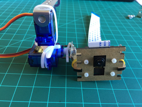
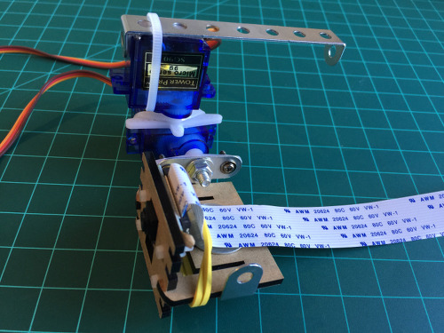
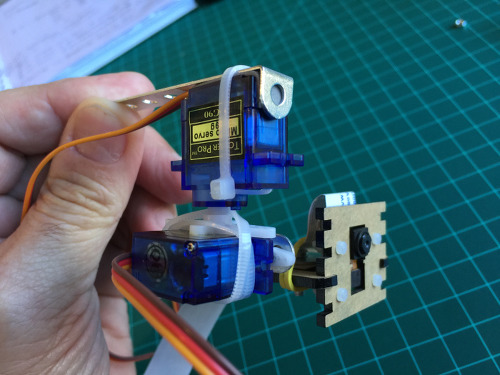
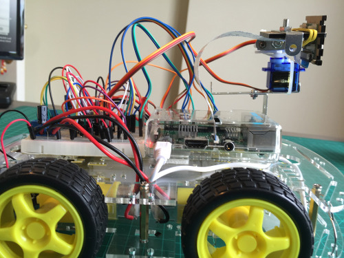
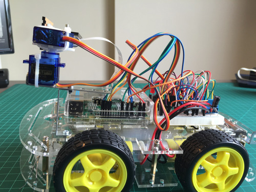
기구 조립 PAN / TILT
이 시장에 여러 팬 / 틸트 메커니즘이 있지만, 난 그냥 종을 묶는 당신이 아래의 사진에서 볼 수 있듯이 물린 함께 매우 간단한을 넣어하기로 결정했다 :
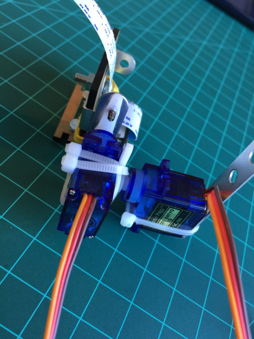
서보를 RPI에 설치하기
위와 같이, RPI에 종의 데이터 케이블을 연결합니다.
은 RPI에 별도의 전압 소스에 + V 두 종을 연결합니다 (물론, GNDS이 연결되어 있어야합니다). 당신이 로봇의 팬 / 틸트 메커니즘을 설치합니다 후에는 DC 모터에 사용 된 것과 동일한 배터리 (9V)를 사용할 수 있습니다. 이 경우에있어서, 6V의 전압 레귤레이터가 요구된다.
서보을 테스트하려면, Servoblaster의 명령 “에코”를 사용합니다. 당신은 백분율로 어느 각도 값을 사용할 수 있습니다. 당신의 팬 / 틸트 메커니즘 최선의 범위를 테스트 :
TILT Servo:
echo P1-11=20% >/dev/servoblaster (looking down)
echo P1-11=60% >/dev/servoblaster (looking front)
echo P1-11=90% >/dev/servoblaster (looking up)
PAN Servo:
echo P1-16=30% >/dev/servoblaster
echo P1-16=62% >/dev/servoblaster
echo P1-16=90% >/dev/servoblaster
우리는 쉽게 스크립트는 종의 위치를 제어 할 수 있습니다. 예를 들어, 우리는 아래의 파일을 작성해야합니다 발견 된 값을 기준으로 카메라 “기대”를 위치 쉘 스크립트를 만들 수 있습니다 :
sudo nano cam_view_front.cgi
#!/bin/bash
echo P1-11=60% >/dev/servoblaster
echo P1-16=62% >/dev/servoblaster
스크립트가 생성되면, 우리는 당신에게 실행할 수있는 권한을 부여해야합니다 :
sudo chmod 755 cam_view_front.cgi
이제 스크립트를 실행합니다 :
./cam_view_front.cgi
에코 명령을 사용하여 임의의 위치에 카메라를 이동 한 다음 새 스크립트를 실행합니다. 당신은 카메라가 자동으로 위치 “정면”으로 돌아갑니다 것을 볼 수 있습니다.
계속해서, 같은 아이디어는 다른 가능한 카메라 위치에 도포한다.
내 페이지를 생성하기 위해, 나는 TILT 5 중간 위치 및 이동하려면 5 중간 위치를 만들하기로 결정했습니다. 당신은 또한 더 단단한 위치의 변화에 대해 “슬라이더”를 사용하도록 선택할 수 있습니다. 당신이 결정한다.
스크립트 “cam_view_front.cgi”에 기재 한 바와 같이 10 개의 새로운 스크립트를 작성, 같은 원리를합니다 사용 :
leftpan.cgi ==> 90%
leftcenterpan.cgi ==> 76%
centerpan.cgi ==> 62%
rightcenterpan.cgi ==> 46%
rightpan.cgi ==> 30%
downtilt.cgi ==> 20%
downcentertilt.cgi ==> 40%
centertilt.cgi ==> 60%
upcentertilt.cgi ==> 75%
uptilt.cgi ==> 90%
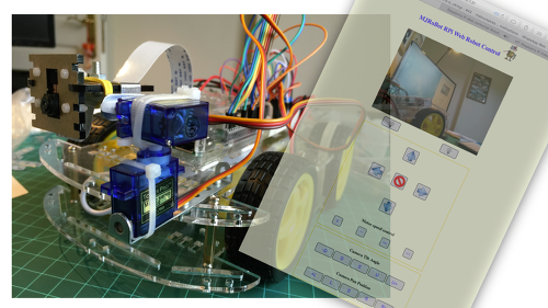
카메라를 제어 ONE PAGE의 HTML을 생성하기
우리는 카메라의 스트리밍 만든 index.html을 사용, 우리가 이전에 만든 스크립트를 실행하는 함수를 호출 10 버튼이 포함됩니다.
이하, 전체 HTML 코드 페이지를 만들 수 있습니다 :
index.html을 페이지에 HTML 코드
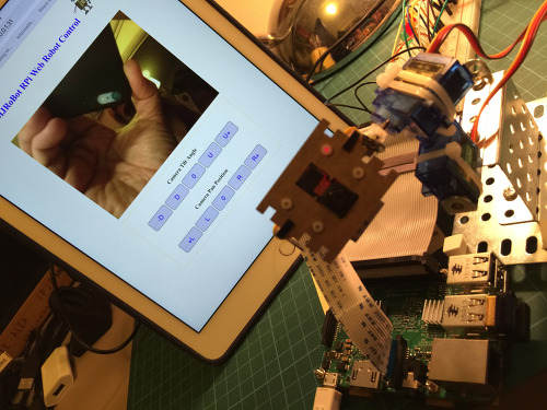
로봇에 카메라와 종들을 포용.
이제 우리는 우리의 RPI 스트리밍 비디오가 인터넷을 통해 카메라를 배치 할 수 있습니다, 우리는 첫 번째 부분에서 만든 로봇 프로젝트의 두 번째 부분을 통합 할 것이다.
포스트의 선두의 블록도, 프로젝트가 통합 될 수있는 방법을 설명하고 아래 회로 접속 방법을 보여
이어서 두 번째 부분 및 부분의 추가 버튼 및 모터의 제어를위한 제 1 생성 함수로 개발 된 웹 페이지를 가지고.


 \
\