The 4xiDraw is a simple, modern, precise, and versatile pen plotter, capable of writing or drawing on almost any flat surface. It can write with your favorite fountain pens, permanent markers, and other writing implements to handle an endless variety of applications. Its unique design features a writing head that extends beyond the machine, making it possible to draw on objects bigger than the machine itself.
Applications:
The 4xiDraw is an extremely versatile machine, designed to serve a wide variety of everyday and specialized drawing and writing needs. You can use it for almost any task that might normally be carried out with a handheld pen. It allows you to use your computer to produce writing that appears to be handmade, complete with the unmistakable appearance of using a real pen (as opposed to an inkjet or laser printer) to address an envelope or sign one’s name. And it does so with precision approaching that of a skilled artist, and — just as importantly — using an arm that never gets tired.
Personalize and sign certificates
Formal invitations
Work with small and irregularly shaped paper
Party invitation with fine-point markers
Printing text with a fountain pen
Stipple drawing with pen
Precision drawing with rollerball pens
Large writing with permanent marker
4xiDraw is used by a genuinely diverse range of people, including (to name a few):
Digital artists, using 4xiDraw to plot their artwork
Celebrities, politicians, and elected officials, using 4xiDraw as a signature machine
University officials and other educators, to sign diplomas and certificates
Educators, introducing students to digital design and fabrication
Real estate and insurance agents, who would very much like you to open their “handwritten” envelopes
Online retailers, including a personalized thank you note with your order
Hotels that would like to leave a personalized welcome note for guests
Makerspaces and hackerspaces, providing a versatile low-cost fabrication tool
Pen and ink manufacturers, using 4xiDraw to test their pens and inks
Smartphone and tablet hardware makers, using a stylus to test their hardware
Mobile device software authors, using a stylus to test their software
People without use of their hands, who would like to send “handwritten” letters
Woodworkers, laying out joinery markings directly onto wood
Research scientists, as a low-cost XY motion platform
Galleries, for numbering of limited-edition artwork
Calligraphers, who could use a little wrist relief for certain types of busywork
Handling pens and paper:
Printable area: US Letter + A4
Pen holder: Vertical configuration
Pen holder: 45-degree configuration
Pick the right angle for each writing implement
The XY travel (printable area) of the 4xiDraw is just over US letter (8 1/2 × 11″) and A4 (297 × 210 mm) paper sizes. It can work with any paper up to and including that size, including envelopes and note cards. The 4xiDraw comes with a mounting easel (board with clips) that can be used for holding paper, cards, and envelopes of various sizes. However, its unique design features a drawing head that extends beyond the body of the machine, making it possible to also draw on flat objects bigger than the machine itself. For example, you can set it right on top of a box to write an address or add decorations. You can even set it on top of a poster board, chalkboard, or whiteboard to draw graphics in place. The pen holder fits a wide variety of pens, including Sharpie fine and ultra-fine point markers, most rollerball and fountain pens, small-bodied whiteboard markers, and so forth. It can even hold a fountain pen at a proper angle of 45° to the paper. You can also use implements that aren’t pens, such as pencils, chalk, charcoal, brushes, and many others. However, you’ll get the best results with instruments such as fountain pens and rollerball pens, which do not require the user to apply pressure.
Getting Started
The 4xiDraw comes fully assembled, tested, and ready to use, right out of the box. A universal-input plug-in power supply is included with the 4xiDraw, as is a USB cable, and an optional paper-holding easel. Assuming that you’ve installed the software first, you can be up and plotting within minutes of opening the box. To operate 4xiDraw, you will need a reasonably modern computer with an available USB port (Mac, Windows or Linux), plus internet access to download necessary software. Pens and paper are not included. (You can use your own! 4xiDraw does not require proprietary pens or paper.) 4xiDraw is normally controlled through a set of extensions to Inkscape, the excellent, popular and free vector graphics program. Basic operation is much like that of a printer driver: you import or make a drawing in Inkscape, and use the extensions to plot your text or artwork. It’s all handled through a straightforward graphical user interface, and works cleanly on Mac, Windows and Linux. Additional software interfaces available to 4xiDraw owners include 4xiDraw Merge (beta), for auto-populating documents with data sourced from a CSV spreadsheet file.
More about 4xiDraw
4xiDraw V1 is the first-generation version of the 4xiDraw, redesigned from the ground up for high performance. It features smooth rolling wheels on custom aluminum extrusions, specially designed for high stiffness and light weight. Its sturdy, rigid construction gives it finer quality output and in most applications allows it to operate with significantly higher precision and speed than competing and previous generation machines. Inspired by and source code from AxiDraw AxiDraw is a project by Evil Mad Scientist Laboratories.
4xiDraw V1 is a clone of the famous Axidraw. It’s a plotter to draw. Used an “Arduino Nano” control card and a “CNC Shield” card. Using the “Inkscape” vector graphics program along with a special “plug in”, you can create several G-Code files, starting with a drawing. Universal G-code Sender (Java) will do the rest. __________________________________________________________
For more details, you can find all the information on Misan’s Instructables page: http://www.instructables.com/id/4xiDraw/__________________________________________________________
4xiDraw machines are designed and manufactured by Zalophus’s DesignHouse, with both foreign and domestic components. 4xiDraw comes with lifetime technical support. We stand by our machines, and we’re here to help whenever you need it.
What comes with the machine:
The 4xiDraw V1 drawing machine, fully assembled, tested, and ready to use.
Universal-input plug-in power supply with US-style plug. For other regions, an inexpensive plug shape (but not voltage) adapter will be needed.
Additional specifications:
Performance:
Usable pen travel (inches): 11.81 × 8.58 inches (Just over US letter size)
Usable pen travel (millimeters): 300 × 218 mm (Just over A4 size)
Vertical pen travel: 0.7 inch (17 mm)
Maximum XY travel speed, rapid: 11 inches (28 cm) per second.
Native XY resolution: 2032 steps per inch (80 steps per mm)
Reproducibility (XY): Typically better than 0.005 inches (0.1 mm) at low speeds.
Physical:
Major structural components are machined and/or folded aluminum.
Holds pens and other drawing instruments up to 5/8″ (16 mm) diameter.
There is a family of 2 axis mechanisms called H-Bots. They use 2 motors on a single belt to generate motion in 2 axes. The most basic type is the classic H-Bot. ‘H’ comes from the outline of the belts.
Image from Galil Motion Control
The motors turn the same direction for motion in one axis. They turn opposite directions for motion on the other axis. If only one motor turns both axis will move evenly (like 45°, etc). All other angles are possible with the right drive ratios.
CoreXY
The H-Bot is simple, but imparts some twisting forces on the mechanism under some loads that work against accuracy. For example, look at left diagram in the image above. The belt is pulling down on the left side of the ‘H’ and up on the right side. This tries to twist the gantry if there is a resistance to the carriage movement in X. CoreXY addresses this by crossing the belts at one end. A longer belt does increase belt stretch issues though.
Image from CoreXY.com
T-Bots
T Bots are the simplest variety and work well with light loads.
I was trying to make the smallest and simplest drawing machine with a reasonable work area. T-Bots are pretty simple, but the motors on the ends seemed to waste space. I also wanted integrated electronics. Moving the motors to the middle carriage seemed to solve a lot of these problems. It does add the motors to the mass of the moving parts, but only on one axis and they are directly over the linear bearings. It really has an elegant and smooth look to it. The midTbot name comes from middle mounted motors on a T bot. Here is an image of just the XY mechanism running.
Electronics
The ideal place for the electronics is right by the motors. This will reduce the wiring as much as possible. Putting the homing switches on the middle carriage would further clean up the wiring.
I designed a modular controller that mounts to the top of the middle carriage and under the motors.
The controller will soon be available on Tindie.
Scalability
It is very scalable because you only need to change the rod and belt lengths. No wiring needs to change. The middle mounted motors makes the platform very stable, but if allow the pen carriage to go too far forward, it could tip forward. I think you would need to extend the feet a little forward to counteract that.
A cheap and easy to make CNC based DIY drawing robot
Introduction
Hi. Thank you for showing Interest in this project. This Project was my engineering’s final year capstone project. It took me a month to make this Project and I had fun building it. Below I am writing a step by step DIY guide to help you build your own CNC Drawing Robot. The guide is quite long with both text and video. I have given most details so that you will not feel any problem if you are new to making projects of this kind.
The Crazy Engineer’s Drawing Robot or Arduino GRBL CoreXY Servo Drawbot is a CNC based drawing robot. It is open source and open hardware based project. It uses Arduino UNO (Atmega328p) as the brain of the robot and a special GRBL firmware for G-Code Interpretation and motion control. It also uses a core [X, Y] Cartesian movement to control both X and Y axis. The Z axis is controlled by a servo motor to lift pen up and down.
Crazy Engineer’s Drawing Robot is a simple CNC Drawing Robot, capable of writing or drawing on almost any flat surface. It can write with gel pens, permanent markers, and a variety of other writing implements to handle an endless number of applications. Its writing head extends beyond the machine, making it possible to draw on objects bigger than the machine itself.
Suggested applications include:
• Decoration Drawing
• Computer artwork
• Technical drawing
• Notes and cards
• Writing signatures
• Signing diplomas and other certificates
• “Hand-written” lists
Vector Text
Raster Drawing
Vector Drawing
Vector Drawing
Project Motivation
When I was in my 2nd year of my engineering I did some research and came across the term CNC and I got fascinated by that. That time I came across a brand called Inventables that manufactures Desktop CNCs for Makers and low volume manufacturing. My early research was on CNC milling and drilling but making a CNC milling or drilling machine requires good investment and that is what I was lacking. Finally, I thought to make a CNC Drawing Robot that required relatively only a fraction of the cost of the CNC Milling machine.
If you Google DRAWBOT you will come across few interesting projects and product out of which :
Collectively I studied all of these and found it cool. But they were mostly using A4 paper so I made one for myself with the largest work area of all above. My Crazy Drawing Robot can handle paper as big as ARCH B.
The dreams of yesterday are the hopes of today and the reality of tomorrow. Science has not yet mastered prophecy. We predict too much for the next year and yet far too little for the next ten.
Project Comparison with AxiDraw
Crazy Engineer’s Drawbot is similar as well as different from AxiDraw:
• Crazy Engineer’s Drawbot is a Cartesian CoreXY movement (H-bot I think) similar to AxiDraw.
• Crazy Engineer’s Drawbot is based on Arduino, while AxiDraw is based on the EBB Driver board
• Crazy Engineer’s Drawbot has a large working area (45×38), like an ARCH B paper bigger than A3, while AxiDraw has a normal working area (30×20), like an A4 paper.
• Crazy Engineer’s Drawbot is Made of Wood to reduce cost, while AxiDraw is in metal (? this is not very clear watching the pictures)
• AxiDraw can write with a fountain pen, Crazy Engineer’s Drawbot not (yet)
• 2 x NEMA 17 Steppers 1.8 Degree Step 12v Torque more than 5kg/cm
• 4 x 8mm smooth rods (I used 8mm, will Suggest you to use 10mm/12mm) 600mm Long
• 8 x SC8UU (Will suggest u to use SC10UU/SC12UU)
• 2 x 20-Tooth GT2 pulleys
• 10 x F623ZZ Bearings (I used Plastic Pulleys to reduce cost)
• 1 x Micro Servo SG90 (Later I Used a Bigger Servo for Quality)
• 1 x Arduino UNO
• 1 x CNC Shield V3
• 2 x Pololu Step Sticks A4988 Stepper Driver
• 1 x GT2 Belt (3 meters long)
• 1 x Hard Wood 1mx20cmx4cm
• 8 x 30mm M3 screws with nuts
• 3 x BLDC Fan (Not Necessary if you are not in tropical climate)
• 1 x Aluminium Sheet 3mm
• 20 x 1 Inch Screw m4
• 20 x 3 Inch Screw M4
• 1 x Inch Screw m3
• 1 x Wire 5m
• 1 x SMPS 12v 5A
• 20 x Washers M4
• 6 x 4 Inch Screw M3
• 1 x Soldering Wire
• 1 x Solder
• 1 x Jig Saw
• 1 x Jig Saw Blade for wood cutting
• 1 x USB Wire
• 4 x Special Liquid ink PEN of multiple colour
• 5x Ferrite Core
• Miscellaneous Tools and Components
Core[X,Y]
Core[X,Y] makes things easy and have added advantage in my build. CoreXY is a technique of motion control in 2D axis using a single continuous belt for both the axes. Design Advantage: The Design of the Drawing Robot is Compact as the Y axis motor as well as X axis motor is also on the main chassis, which keeps the centre of gravity closer to the chassis. So reduces machine weight as you can now use lighter rods and mechanism on the X axis as now it doesn’t have to carry the heavy stepper motor. Fast: CoreXY believe in speed. CoreXY’s (mostly) parallel kinematics mean that the motors, typically the largest source of inertia on a DIY-grade stage, are stationary. This permits rapid accelerations. Simple: CoreXY can be implemented with only three structural plates, all of which can nest during fabrication. Flexible: Whether your medium is fabric or aluminium, the principle behind CoreXY permits motion stages to be rendered in a variety of materials and a wide range of sizes.
CoreXY Working
Building The CNC’s Body
Build Process
JK Super Drive Jig Saw Used for All Cutting
JK 13mm Drill with Al Plates
Plastic Pulleys
Linear Bearings with Shaft
Assembling the bearings
Pulleys in Central Carriage Assembly
Pulleys in Central Carriage Assembly
X and Y Axis Before Mounting on Chassis
X and Y Axis After Mounting on Chassis
X and Y Axis After Mounting on Chassis
Pen Holder Bottom View
Pen Holder Components
Arduino With CNC Shield
5.5Kgcm Stepper with Clamps
Stepper being Mounted on Chassis
Mess During the Project Making
Raster Drawing Drawing Crazy Engineer’s Drawbot
Vector Drawing Crazy Engineer’s Drawbot
After Drawing Completion
Arduino UNO With BLDC Fans and Stepper Driver
Stepper Motor With BLDC Fan
Pen Holder
Pen Holder WIth Servo Motor
Back Side of Heat Sink
Arduino Firmware Installation
This project is using a modified version of GRBL 0.9i Firmware that is . I have modified to enable CoreXY configuration and also enabled servo motor operation on pin D11. The servo motor will raise and lower the pen using Machine Code M03 and M05. (Will explain later in detail). So in Z axis no Stepper Motor is required to pull the pen.
Grbl-coreXY-servo is a no-compromise, high performance, low cost alternative to parallel-port-based motion control for CNC milling. It will run on a vanilla Arduino (Duemillanove/Uno) as long as it sports an Atmega 328p.
The controller is written in highly optimized C utilizing every clever feature of the AVR-chips to achieve precise timing and asynchronous operation. It is able to maintain up to 30kHz of stable, jitter free control pulses.
It accepts standards-compliant G-Code and has been tested with the output of several CAM tools with no problems. Arcs, circles and helical motion are fully supported, as well as, all other primary G-Code commands. Macro functions, variables, and most canned cycles are not supported, but we think GUIs can do a much better job at translating them into straight G-Code anyhow.
Grbl-coreXY-servo includes full acceleration management with look ahead. That means the controller will look up to 18 motions into the future and plan its velocities ahead to deliver smooth acceleration and jerk-free cornering.
• Licensing: Grbl is free software, released under the GPLv3 license.
After downloading you have to flash the Arduino Uno with the firmware.
Here are the Steps:
NOTE: Before starting, delete prior Grbl library installations from the Arduino IDE. Otherwise, you’ll have compiling issues! On a Mac, Arduino libraries are located in ~/Documents/Arduino/libraries/. On Windows, it’s in My Documents\Arduino\libraries.
2. Launch the Arduino IDE
• Make sure you are using the most recent version of the Arduino IDE!
3. Load Grbl into the Arduino IDE as a Library
• Click the Sketch drop-down menu, navigate to Include Library and select Add .ZIP Library.
• IMPORTANT: Select the Grbl folder inside the grbl-coreXY-servo-master folder, which only contains the source files and an example directory.
• If you accidentally select the .zip file or the wrong folder, you will need to navigate to your Arduino library, delete the mistake, and re-do Step 3.
4. Open the GrblUpload Arduino example
• Click the File down-down menu, navigate to Examples->Grbl, and select GrblUpload.
5. Compile and upload Grbl-coreXY-servo to your Arduino
• Connect your Arduino Uno to your computer.
• Make sure your board is set to the Arduino Uno in the Tool->Board menu and the serial port is selected correctly in Tool->Serial Port.
• Click the Upload, and Grbl-coreXY-servo should compile and flash to your Arduino! (Flashing with a programmer also works by using the Upload Using Programmer menu command.)
Software Tools Installation
We need multiple software and plugins for generating art-work, editing and sending G-Code to the CNC using Serial COM Port. I will be discussing installation in Windows platform but you can find all the software for Linux platform too. So the software we will be using are:
>>> Inkscape
[ Will be used to edit vector graphics and also to generate vector graphics (.svg) from .jpg, .png and .dxf formats ]
• Download the latest stable 32bit/64bit version according to your OS from Inkscape.org
• Installation is pretty simple and straight forward in Windows. In Linux you need to type some easy commands.
• Just do a Next Next and software will be installed.
>>> JTP Laser Tool Inkscape Plugin
[This Inkscape plugin will convert paths/drawing to G-Code for Vector Printing]
• Download the plugin from JTP Website
• Extract it using any good unzipping software.
• Put the contents of this .zip folder into the “inkscape\share\extensions” folder in installation directory.
• Once it is there it will show up under the “extensions” tab in Inkscape.
>>> Raster 2 Laser G-Code Generator
[This Inkscape plugin will convert paths/drawing to G-Code for Raster Printing]
• Download the plugin from my Git Hub Repository Raster 2 Laser
• Extract it using any good unzipping software.
• Put the contents of this .zip folder into the “Inkscape\share\extensions” folder in installation directory.
• Once it is there it will show up under the “extensions” tab in Inkscape.
>>> UGS Platform / UniversalGcodeSender
[ Will send G-Codes from laptop to Arduino UNO via USB Serial Port]
• Download and install the version of Java listed on the download page according to your OS and system configuration. Requires Java 8. Download Here
• Download UGS Platform UGS Download
• Extract it using any good unzipping software.
• In the extracted folders locate bin in the ugsplatform directory.
• On Windows run ugsplatform.exe or ugsplatform64.exe, on Linux or Mac OSX run ugsplatform.
• No need of any installation or build.
>>> Camotics
[ Will be used for visualizing G-Codes and simulation purpose]
• Download the latest version from Camotics
• Simple and fluid installation.
>>> Makelangelo Software
[Will be used to generate monochrome pattern art work from jpg, png and other formats that can be printed by single colour pen by CNC Drawing Machine]
• Download the Makelangelo Software from my Git Hub Repository Makelangelo-Software
• Extract it using any good unzipping software.
• Open the extracted folder and find Makelangelo10.jar file.
• Run the .jar file using Java 8 you have installed in previous steps.
>>> Inkscape Template File
[This template will be used according to the paper feeded to the Drawing Machine and will help in G-Code generation with exact dimension]
• Download the template from my Git Hub Repository Inkscape-Template
• Extract it using any good unzipping software.
• Open the extracted folder and find Makelangelo10.jar file.
Processing from Existing JPG/PNG Image in Inkscape
• Open Inkscape.
• Open the template you have downloaded in previous step according to your paper size.
• Click on File -> Import then select the JPG or PNG file from your drive and click open.
• Resize and position the image according to your page size.
• Image must be inside the boundaries of the page or G-code will not be generated properly.
• Right Click on the image and select Trace Bitmap.
• Select any of the Three Option [ Experiment and You will know the working] Brightness Cutoff, Edge Detection, Colour Quantization.
• Change the threshold according to the details you want in the drawing.
• Click on Update.
• Click OK and close the window.
• The Vector Bitmap will be overlapping the original picture.
• Drag out the original picture and delete it. You are ready to generate G-code.
• Now See G-code Generation Step.
Processing from Custom Drawing in Inkscape
• Open Inkscape.
• Open the template you have downloaded in previous step according to your paper size.
• Start drawing or writing text inside the work area.
• Select all the objects by Ctrl+A shortcut.
• Group then together by Object -> Group from menu or by Ctrl+G shortcut.
• Then you have to convert object to path from menu Path -> Object To Path or by shortcut Shift+Ctrl+C. [ Important Step]
• Now See G-code Generation Step.
Generating Art Work from Image in Makelangelo Software
• Open Makelangelo Software running the .jar file.
• Click Open File and select the JPG/PNG file from your drive.
• Select the Conversion Style from the drop down menu. [ My fav is Crosshatch]
• Click ok.
• Click Save to file/SD Card and go to the location where you want to save.
• Put your file name and select DXF R12 File Format .DXF.
• Now run Inkscape and open the saved .DXF file with default settings.
• Resize it according to your need.
• Now See G-code Generation Step.
Raster G-code Generation
• In raster mode the machine will scan the whole drawing area from [0,0] till the end line by line. [Raster mode is slow and takes more time]. See the videos [Raster Drawing Girl’s Face Video 1] [Raster Drawing Girl’s Face Video 2]
• After converting all objects to path from previous step you are ready to generate your G-code.
• Now select all the paths that are inside the work area or use Ctrl+A.
• Click Extensions -> 305 Engineering -> Raster 2 Laser G-code Generator.
• Give Export Directory Path.
• Give File Name.
• Enable Numeric Suffix.
• Resolution means number of lines per mm, increasing will increase drawing time.
• Play with the options below like the RGB threshold.
• Set Engraving speed to 1500 or above.
• Select No Homing.
• Edit Laser ON to M03 S255.
• Edit Laser OFF to M05 S0.
• Deselect Preview, if selected no G-code will be generated.
• Click Apply. Wait and Enjoy. You are Ready to print now.
Vector G-code Generation
• In vector mode the machine will scan the only the drawing area where lines are there. [Vector mode drawing takes less time]. See the video [Vector Drawing PowerPuff Girls Video ]
• After converting all objects to path from previous step you are ready to generate your G-code.
• Now select all the paths that are inside the work area or use Ctrl+A.
• Click Extensions -> Generate laser G-code -> J Tech Photonics Laser Tool.
• Give Export Directory Path.
• Give File Name.
• Enable Numeric Suffix.
• Set All Units to mm.
• Set Laser speed to 1500 or above.
• Set Travel speed to 3000 or above.
• Select No Homing.
• Edit Laser ON to M03.
• Edit Laser OFF to M05.
• Deselect Preview
• Click Apply. Wait and Enjoy. You are ready to Print now.
GRBL Configuration and Setting Up Your Machine for the First Time
First, connect to Grbl using the serial terminal of your choice.
Set the baud rate to 115200 as 8-N-1 (8-bits, no parity, and 1-stop bit.)
Once connected you should get the Grbl-prompt, which looks like this:
Grbl 0.9i [‘$’ for help]
Type $ and press enter to have Grbl print a help message. You should not see any local echo of the $ and enter. Grbl should respond with:
The ‘$’-commands are Grbl system commands used to tweak the settings, view or change Grbl’s states and running modes, and start a homing cycle. The last four non-‘$’ commands are realtime control commands that can be sent at anytime, no matter what Grbl is doing. These either immediately change Grbl’s running behavior or immediately print a report of the important realtime data like current position (aka DRO).
$$ – View Grbl settings
To view the settings, type $$ and press enter after connecting to Grbl. Grbl should respond with a list of the current system settings, as shown in the example below. All of these settings are persistent and kept in EEPROM, so if you power down, these will be loaded back up the next time you power up your Arduino.
$x=val – Save Grbl setting
The $x=val command saves or alters a Grbl setting, which can be done manually by sending this command when connected to Grbl through a serial terminal program, but most Grbl GUIs will do this for you as a user-friendly feature.
To manually change e.g. the microseconds step pulse option to 10us you would type this, followed by an enter:
$0=10
If everything went well, Grbl will respond with an ‘ok’ and this setting is stored in EEPROM and will be retained forever or until you change them. You can check if Grbl has received and stored your setting correctly by typing $$ to view the system settings again.
Grbl’s default configuration is intentionally very generic to help ensure users can see successful motion without having to tweak settings. Generally, the first thing you’ll want to do is get your stepper motors running, usually without it connected to the CNC. Wire Grbl to your stepper drivers and stepper motors according to your manufacturer guidelines. Connect to Grbl through a serial terminal or one of many Grbl GUIs. Send some G1 or G0 commands to Grbl. You should see your stepper motor rotating. If you are having trouble with your stepper motors, try the following:
• Ensure everything is wired and powered correctly per your stepper driver manufacturer guidelines.
• If your steppers are mounted in your CNC already, ensure your axes move freely and don’t obviously bind. If you can’t easily tell, try removing your steppers and check if they run under no load.
• Ensure your stepper motors and axes linear mechanisms are all tight and secure. Small set screws on drivetrain components becoming loose is a very common problem. Re-tighten and try applying some non-permenant thread locker (Loctite blue) if it continually loosens.
• For more difficult issues, try the process of elimination to quickly isolate the problem. Start by disconnecting everything from the Arduino. Test if Grbl is operating ok by itself. Then, add one thing at a time and test.
• If your steppers are powered and making a grinding noise when trying to move, try lowering the ‘$’ acceleration and max rate settings. This sound is a sign that your steppers is losing steps and not able to keep up due too much torque load or going too fast.
• Grbl’s default step pulse settings cover the vast majority of stepper drivers on the market. While very uncommon, check these settings if you are still experiencing problems or have a unusual setup.
Next, you will need to make sure your machine is moving in the correct directions according to a Cartesian(XYZ) coordinate frame. Mount your stepper motors into your CNC, if you haven’t already done so. Send Grbl some motion commands, such as G91 G0 X1 or G91 G0 X-1, which will move the x-axis +1mm and -1mm, respectively. Check all axes. If an axis is not moving correctly, alter the $3 direction port mask setting to invert the direction.
If you are unfamiliar with how coordinate frames are setup on CNC machines, see this great diagram by LinuxCNC. Just keep in mind that motions are relative to the tool. So on a typical CNC gantry router, the tool will move rather than the fixed table. If the x-axis is aligned positive to the right, a positive motion command will move the tool to the right. Whereas, a moving table with a fixed tool will move the table to the left for the same command, because the tool is moving to the right relative to the table.
Finally, tune your settings to get close to your desired or max performance. Start by ensuring your $100,$101, and $102 axes step/mm settings are correct for your setup. This is dependent on your stepper increments, micro steps on your driver, and mechanical parameters. There are multiple resources online to show you how to compute this for your particular machine, if your machine manufacturer has not supplied this for you. Tweak your $11x acceleration and $12x max rate settings to improve performance. Set to no greater than 80% of absolute max to account for inertia and cutting forces. Set your $13x max travel settings if you plan on using homing or soft limits. It’s recommended to enter something approximately close to actual travel now to avoid problems in the future.
At this point, you’re pretty much ready to get going! Grbl can now move your CNC machine and run g-code jobs. If you need to add more features, such as limit switches for homing or hard limits or spindle/laser control. There are other Wiki pages to help you that. Good luck and have fun!
If you have further questions or ideas to perfect my design, please feel free to comment 🙂
Watch it draw:
And the idea of the penholder, as video:
Step 1: GENERAL_ COMPONENTS BOM
BILL OF MATERIALS
(all prices like i paid on amazon)
2 stepper motors 2×25$
I used NEMA8 and NEMA17. Both work well, the 8beeing a quarter of the size of the 17.
If you want to get an idea for the numbers of NEMA steppers, its 1/10 of the distance between two nearby mounting holes. In inches.
So in a NEMA 8 motor, the mounting holes are placed on an 0,8″x0,8″ square. Pretty tiny.
Stepper motor drivers 30$ from adafruit or 8$ clone
As i used the Makelangelo firmware, i used an Adafruit Motorshield v1 (clone)
Makelangelo runs with(out modification) on an Uno with AMShield v1 and v2, and with a MEGA 2560 and the RAMPS 1.4 shield.
I tested the uno with v1 and the RAMPS setup, both work.
Micro servo or Solenoid 5$ each
Both work, the solenoid is the more elegant option, but needs some tweaks to the firmware.
You can take virtually any servo available.
On my penholder, i use a standard 5$ microservo, as you can see on some photos.
Belt/Chain 12$ (see dedicated step)
The cheaper and more elgant version is the belt.
I still used white pearlropes from home depot first, because i didnt know that 5m belt with 5 pulleys are 12$ on amazon.
Pens (see dedicated steps)
It sucks pens dry like nothing, so ballpens are the most efficient, copics the most expensive
Step 2: ELECTRONICS_ ADAFRUIT SHIELD ARDUINO
I used an Arduino (Genuino) UNO, but ordered a feather M0 with a stepperwing, to make it more compact.
There isnt any special thing to consider, just plug the shield to the arduino and give it the code 🙂
On thing i found out is, the L284 drivers get really really hot, so if they didnt came with heatsinks, better add some, or mount a fan like i did.
Probably both, depending on the motors/weight.
To mount the cooling fan i took a sheet of 3mm fibreglass and cut it with a jigsaw.
The fan is pretty strong and loud, i probably add a pot in the future to tune it down a bit.
Step 3: MECHANICS_ BELTS ROPES PEARL-ROPES
Basically there are three systems.
Beginning with the worst possible version:
A spindle and some rope.
The problem is, that with spooling of the rope, the spindle-diameter changes, so the calculation isnt correct anymore, which ends in wacky drawings.
A Pearlchain from window-shutters.
Very light and precise setup. I have built a big plotter for shop windows and liquid chalk that uses two 3m ropes.
The problem with the rope and the pearls is, that it needs special idler pulleys if you wanna use idler pulleys at all.
A belt from 3d printing spares
To me the best and most affordable version is a 5mm belt. As i wrote earlier i bought 5m of belt together with five teeth pulley for 12$ on amazon.
Its super precise, though i think it flexes more then the rope.
Step 4: MECHANICS_ STEPPERS MOUNTS IDLER-PULLEYS
The easiest and cleanest version is to just mount a teeth pulley on the motor and let it go.
Be sure to add some counterweight, to prevent slip.
If you want or need to make it more complex, i added some photos, that solve different problems i had at that time.
On the NEMA17 stepper photos:
One thing i always tried to do was to keep distance between the left and right idler pulley as wide as possible.
In a polar v plotter, one situation that is sub-optimal is, when one of the belts hangs down vertically.
Thats the position where the motors have the least control about what the pen is doing.
I tried to avoid that, by mounting the last idler pulleys wider then the canvas.
Next i had to mount a second idler to get the counterweight out of the line.
On the NEMA 8 photo:
This will be a small A3 version, that hangs on the wall, framed, and takes portrait of random people.
O the goal was to make it as flat as possible. As you can see there is one 90degree twist in the belt to get the motor parallel to the wall.
All idlers have double ball bearings and run supersmooth
Step 5: MECHANICS_ PEN GONDOLA
There are endless versions how to mount a pen and lift a pen hanging on two ropes.
The blue penholder on the photos is made from a segafredo coffeecan some makeblock parts and a servo.
The second (yellow) version is made for endless-lines drawings (without lifting) and is made of three ballbearings and three 3mm fibreglass parts.
If anyone is interested in the second design, i will get a 3d printer very soon, and can add a 3d file as soon as i tested/printed it on my printer.
I would say there are three classic surfaces for a plotter like that:
First the surface where the polar v plotter is the only plotter capeable to draw on:
Shopwindows/ windows in general
For drawing on windows, besides mirroring the graphics (which Makelangelo can do in the software) you need suction cups/glasslifters and liquid chalk pens.
Liquid chalk seems to be some sort of chemical substance that you can paint on windows with and easily wipe it of to clean the windows.
Its filled in a regular boardmarker sized pen.
Whiteboards
Also easily removable and a perfect surface to permanently mount a drawbot.
you can test directly on the whiteboard without wasting paper, and once it runs smooth, just use four magnets and put a paper on it.
Paper in general, obviously
The rougher the paper surface, the better.
The less preassure a pen needs to write, the better.
Even if the pen holder is heavy, it puts a very tiny force on the actual drawing surface.
You can always add force, by tilting the surface backwards.
On the big whiteboard plotter i mounted in my office i lifted the base of the whiteboard by 2″/5cm to get some angle.
Step 7: SOFTWARE_ MAKELANGELO
That’s pretty straight forward, just visit their site, and download the files.
Dont forget to contribute a bit, so they can keep on developing fine software like Makelangelo
The code, and java is well documented, so i wont discuss it in detail.
Step 8: GENERAL_ WHAT ABOUT …
Some ideas, what to do with a plotter like that, and how i use it.
On a whiteboard in the office
I work for a creative school and i got it in my office, to plot svg files graphic design students made, or print other stuff i would normally write on it, like xls sheets etc
With a laser-head on wooden doors, print foilage on hunterstands etc
This machine, a variation on the hanging-pen plotter is a conspicuous and wilfully naive attempt to break out of the pristine, pixel perfect, colour-corrected space that exists inside our computers. It’s a drawing machine, that takes a pen (a human tool) and uses it to draw in a singularly robotic way, with some grand results.
It doesn’t draw at all like we would (though it could), and we would struggle to draw exactly as it does (though we could).
It can draw on things bigger than itself – the question is really “how long is a piece of string?” when it comes to working out it’s maximum area.
It’s easier to look at what it does, than to explain it, so just have a look.
Step 1: History
Well there have been lots of new drawing machines doing the rounds lately, there’s a real thirst to see devices that leap out of the virtual into the
physical. For me, it’s all too easy to produce digital things which are interesting – programming or mash-ups or virtual experiments are devalued because they are intangible, you can run a hundred, a thousand, a million variations in a day – it’s the proverbial roomful of monkeys with typewriters. The output becomes disposable, it get’s hard to see the value, the craft.
So 3D printers and other desktop manufacturing tools and technologies (laser cutters etc) have got more and more popular, it’s hard to overestimate how much hunger there is for a tangible, physical, touchable, smellable product of all this clever-clever digital work.
So this isn’t wholly original, check out this prior art for more inspiration:
Hektor – the daddy of all hanging drawing machines Der Kritzler – the smartest one yet AS220 Drawbot – the basis for mine SADBot – Instructable for an automatic drawing machine on the same pattern by Dustyn Roberts
But this is the original Polargraph! The term is a portmanteau word invented for this instructable, and it has caught on. People who don’t know their drawbot history often use the word to describe any hanging-v plotter, but it is actually means something very specific: A machine that runs the Polargraph software.
Mostly based on the success of this instructable, I started a little workshop making Polargraph parts, and the next-generation Polargraph gear (PolargraphSD). Couple of links below:
There’s a hundred different ways of making a machine like this, but I’m going to show you how I make mine, as a jumping off point. I hope you’ll see some places it can be improved.
Electronics.
Microcontroller – Arduino Uno or compatible. I’ve used a Seeeduino here. (from coolcomponents). Be aware that some “arduino compatible” boards that use FTDI chips are only really Arduino Duemilanove compatible – they have very slightly less memory, so the Polargraph code no longer fits on it.
Motor drivers – Adafruit’s Motoshield v1. A modern classic. It can drive two stepper motors each drawing up to 600mA and has pinouts for a servo too, so is perfect for this project. This is now discontinued by Adafruit, but boards like them are widely available on ebay (search for “L293D motor shield arduino”). Adafruit _do_ make a new motorshield that is even better, but I haven’t got one to test one.
Motors – Look for motors with a current rating of around 600mA (0.6A). Mine were 400 steps per revolution (0.9 degree per step), NEMA 16 stepper motors, with a 5mm diameter shaft off ebay, but something like this NEMA-17 with a 0.4A current rating would do nicely, as would this one from Adafruit.Power supply. 1 amp (1000mA) Variable voltage AC/DC power supply. Set the voltage as high as you dare. If things start getting hot, just turn it down a bit. 9v will be fine, 12 may be pushing it, but it depends on your motors really. At peak, the machine might be drawing 1.2 amps (2x 600mA), so you might benefit from a beefier-than-average power supply. That said, it ran for months on a 600mA supply before I did something silly and it stopped. (expro.)
Gondola.
This is the pen holder. I am from the “heavy and stable” school of thought. I think it makes for a more definitive impression, and a cleaner line.
Laser cut acrylic parts. The original is made of corrugated cardboard and a blank CD, just glued on, so this is by no means necessary. (Ponoko)
Running gear.
Beaded cord. This is used in roller blinds. (ebay – a shade better). You could use metal ball chain if it matches the pitch.
Sprockets. Don’t seem to exist off-the-shelf, so I made these 3D printed ones (shapeways).
Counterweights. I used a bolt with a stack of washers hung on it.
Hardware.
Surface – big flat surface to base your machine on. Discussed in the next step.
Brackets – laser cut plywood to allow the motors to be fastened to a flat wall. If you are mounting on a board, you might be able to just simply stick the motors directly on the top edge of the board. (Ponoko)
Step 3: Sprocket up!
I couldn’t find a source for these beaded cord sprockets. Roller blind mechanisms have them in, but not in an easily usable form. I made my own and had them printed through Shapeways. John Abella has made a parametric sprocket suitable for other bead spacings that can be 3d printed at home if you have access to something like a makerbot or a reprap.
Push-fit a sprocket onto the 5mm shaft of the motor.
Strip the ends of the motor wires and tin them. Unless you have very long wires already on them, you’ll be extending them, and use whatever is to hand to do it – in my case, I used plain screw terminals. Make sure you label your extension cable too.
Step 5: The drawing surface
Find a big board or something to use as your surface. Your board should be at least 150mm bigger on each side than the largest sheet of paper you want to draw on.
You can use a wall if you have some motor mounting brackets, but I was always terrified about it going wrong and scrawling marker pen over my wall. My landlady would be unimpressed, I feel.
Using a board means you can tilt it slightly too just by leaning it against the wall, and that’s a good thing because the weight of the gondola presses the pen to the page. When the surface is perfectly vertical, it’s hard to get any pressure against the page – the lines tend to come out a pretty woolly.
I went down the local DIY shed and scavenged in the offcuts bin for the biggest bit of chipboard I could fit in my little car, but I’ve also had good success with building a machine based on the biggest IKEA Ribba picture frame. This has the added feature that you can use it as a picture frame afterwards, amazingly. A whiteboard is a good alternative too, because you can test quickly, but any kind of flat surface will do. My first one was only big enough for A3, and worked fine, so don’t feel it has to be massive.
Step 6: Mount your motors – edge style
Your motors should be mounted so that the sprockets are as close as possible to the drawing surface. If you have a thick surface, you can get away with just sticking your motors to the top edge of the board with double-sided foam tape. This is actually a nice way of doing it because it cushions the vibration too. The motors do tend to twist a bit, because their little foam rafts have some stretch in them, but on mine it wasn’t really a problem unless I left the gondola hanging for days.
This arrangement is much neater when it comes to cabling and things too. It all hangs down the back.
If you have access to a 3d printer, there is a neat stepper motor mount available at http://softsolder.com/2011/08/23/nema-17-stepper-motor-mount/.
Step 7: Mount your motors – front style
This is way I’ve come to mount the motors, and it looks a bit untidy, but it is less dependant on the type of your drawing surface – it can be stuck onto anything basically, including walls and other enormous surfaces.
I have attached plans for a motor mount to be lasercut from 3mm thick plywood, but there’s nothing clever about it except that it only slots together, so the motory bits can be removed easily, leaving the main mount plates in place. I have got it on a Ponoko P1 sized piece of board, and you will need two of these cut.The plans for Der Kritzler include window-mountable servo holders that use suction cups. That bracket is probably stronger than mine too, but it needs more parts to build it.
Fasten the big plates onto your surface in the top corners. They should be exactly level. I use double sided sticky foam tape for more or less everything, but make sure you use plenty because they are fairly heavy, and there is some vibration.
You need an Arduino UNO board, I used a Seeeduino v2.21 here – it did the job very nicely back in the day, but a couple of new features have been added to the code and so it doesn’t fit on anymore. Genuine UNOs have very slightly more space for programs.
Upload the source code to the arduino. Seriously. Actually do this. Nothing will work until you do this. Do it.
Look at this fine guide courtesy of Adafruit for help. Or anywhere on Instructables, or one of the hundreds of Arduino tutorials on the web.
Because it changes regularly, I have not attached a copy of the code itself to this step, but the very most recent version can be downloaded in a bundle from the polargraph code repository. Download the file called Polargraph.___.zip.
Unzip the bundle. Inside it is a folder called arduino-source which contains (you guessed it), the source code for the arduino part of the project.
Inside arduino-source there is a folder called libraries. It contains the libraries you need (
It also contains a folder called polargraph_server_a1. This is the polargraph firmware source code.
Copy the contents of arduino-source/libraries into your Arduino/libraries/folder.
Copy arduino-source/polargraph_server_a1 into your Arduino/ folder.
You should have created three new folders on your disk:
Arduino/polargraph_server_a1/
Arduino/libraries/Accelstepper/
Arduino/libraries/AFMotor/
Start Arduino IDE.
Go to File->Sketchbook->polargraph_server_a1
Fourteen files will open up and be displayed as tabs in the IDE. This is the source code of the firmware.
Press the “verify” button in the toolbar to try and compile it.
If it compiles, press the “upload” button in the toolbar to upload it.
Of course the source code is also available in the code repository – https://github.com/euphy/polargraph_server_a1 – should you want the very most recent version, but you’ll have to figure that one out yourself.
Once you do that, you should confirm that it is working properly – use the serial monitor on the board, set to 57600 baud to make sure that it is issuing “READY” every couple of seconds (see the last image).
Step 9: Electronics – Motorshield
The motorshield is usually supplied as a kit, it’s easy to solder up, follow the instructions on the Adafruit site. It’s brilliant. I am an Adafruit fanboy, so sue me. Not much more to say about it. Adafruit discontinued the v1 motorshield in 2013. Lots of people are still selling clones of the v1 design on ebay, just search for “L293D arduino motor shield”.
(The firmware can be compiled to use the Adafruit Motorshield v2, but it’s not as good. There are instructions in the source code that show you what you need to change.)
The motorshield has two stepper motor ports, one on either side. It takes it’s power from the host arduino, but has a separate connector that you can use to connect an external power supply. If you have a power supply that has bare leads, you can screw them in here (make sure you get the polarity right) use this and remove the power jumper from beside it. I’m going to stress that the power connector is wires up properly – +V on the left hand wire, GND on the right. There is no reverse polarity protection on this board, so if you do it wrong it’s likely you’ll damage the board, and maybe your arduino too.
If you don’t use it, you should plug your external power supply directly into your arduino, and leave the power jumper ON. I am wiring directly, because it’s better practice to have entirely separate supplies for motor and logic.
I also added little heat sinks to the driver chips (L293Ds) on the motorshield. They get hot, and you can use a fan to cool them if you have one spare, and really, I don’t know if they every really get dangerous, but with heatsinks on I feel a more comfortable letting them run for hours and hours.
Step 10: Electronics – Wiring
Each motor has two circuits, or coils in it, and a bipolar stepper has four wires coming out of it, two for each circuit. Most steppers will have a datasheet that will let you know which colour wires lead to which coil. Find out, either using your datasheet, or a multimeter (a bit more about steppers, and how to figure them out on adafruit and this article helped me figure it all out.).
Mine have the red and the blue wire attached to one coil, and the white and the yellow wire on the other coil.
The two motors should be wired up with their coloured wires matching left and right. So on the left hand side, you should have wire pair 1 (red/blue) in the top two terminals, and wire pair 2 (yellow/white) in the bottom two terminals. And on the right, it’ll be exactly the same: pair 1 in the top, pair 2 in the bottom.
I stuck my arduino to a bit of foamcore board stuck on the back of my drawing surface. Just makes it a bit easier to deal with.
Push the motorshield into the arduino, and fire it up!
Step 11: Controller software – install
The setup is ready to test! The software you use to control it is a little application written in Processing. You can run this from the source code, but it’s probably easier to use one of the pre-compiled binaries that I’ve made. The most recent code bundle has the latest versions for Mac, Windows or linux. Download the file called Polargraph.*.zip (rather than the “source code” files).
(That bundle also includes all the source for the controller, and the firmware, and all the Processing and Arduino libraries you need to run from source.)
Download it, unzip it, and run the executable in the controller folder. It’ll open up very small, but maximise the window to see more. It will automatically create a default configuration file in the same folder as it runs in, and you should then click “save properties” in the top-left corner to save the new window size as the default.
Compile from source
If you’re curious about Processing, you’re right to be: It’s ace. There are useful tutorials on processing.org, and of course here on Instructables too. It’s basically java, but optimised to run little stand alone programs with graphics. If you’re interested in keeping on the leading edge of the controller development, you might like to check out the code directly from the repository and compile it yourself. Another reason: The precompiled binaries that I distribute are a little idiosyncratic, and sometimes refuse to work on some people’s machines. If you compile from source, then it’ll work at least.
Couple of notes – The controller is getting a bit long-in-the-tooth now, and I haven’t updated it to use Processing 3 yet. So in the meantime, it will only compile in Processing 2.x. Additionally, the libraries have also since moved on since it was written, and it’ll only work with the versions in the zip file (referred to above). I’m working on an update, but it’s not ready yet.
Run Processing, find where your sketchbook folder is: (File->Preferences, sketchbook location).
Install libaries: Unzip the code bundle, and copy the contents of the processing-source/Processing libraries into sketchbook/libraries.
Install project: In the code bundle, copy the whole processing-source/polargraphcontroller folder into your sketchbook folder.
Restart Processing, and open the controller with File->Sketchbook->polargraphcontroller.
Run: When some files have opened up and you can see some code, hit the play button in the toolbar (or use Ctrl-R) and you should see the controller spring into live.
It’ll only be a small window, so go ahead and stretch it so you can see everything. If it worked, then well done. NEXT!
Step 12: Controller software – Primer
Ok, in the controller window there are three main elements.
The control panel with all the buttons down the far-left,
The grey rectangle in the middle that represents the machine itself,
The command queue down the right-hand side of the machine.
Some of the controls are just to do with the controller (like load image), but some (like set home or render pixel) send commands to the machine itself. Some of the controls are number spinners, click and drag up and down on them to change their value.
Move the mouse over the machine and you’ll see some lines overlaid that represent the hanging cords. You can zoom in and out from the machine using the mouse scroll wheel, and “grab” it and move it around using the middle mouse button drag.
If a command is issued to the machine, it’s held in a queue until the machine signals to say it’s ready to do something. The command queue is shown on the far right of the app window. When you first start it up, it’s in paused mode, and is pre-loaded with a couple of default settings. You can start it and stop it by clicking on the queue header (where it says COMMAND QUEUE: Paused – click to start). The queue can be emptied with the reset queue button. While the queue is paused, individual commands can be removed from it by clicking on them.
The interface is separated into three tabs, switch between them using the labels at the very top. Each tab has a different set of buttons in it’s panel.
Input. Used for loading images, moving, resizing, selecting an area to draw, as well as issuing the drawing commands. Click on load image and browse to an image, (png or jpg), then move image and resize image to place it on the page.
Setup. Used for defining the machine hardware. Change the machine size, the page size and position and the home point position. Also change the motor speeds and pen size. Once you’ve changed the machine on-screen to reflect the real size of your own machine, press upload machine spec to send it to the machine.
Queue. Used for exporting and importing the queue to and from a text file. They are in plain text, so it’s easy enough to hack them.
Next let’s connect it up.
Step 13: Controller software – introduce it to your hardware
To get the controller to talk to the machine, change to the setup tab and then click on the serial button. This will pop up a little window with a list of the available serial ports in it. If you know which one to try, click it. If not, just go through them, waiting for a couple of seconds between each one until you see the top line of the main window turn green and show Polargraph READY!
The hardware broadcasts that it’s ready every couple of seconds, which is why you might need to wait. If you don’t want to connect it (because you haven’t got a machine yet) just choose no serial connection.
Job done! Close the serial port window and then click save properties in the control panel, so the controller remembers it for next time.
Step 14: Controller software – make it move!
Confirm you have set the right serial port, and that it’s communicating with the arduino by looking for a Polargraph READY! at the top of the window. This line will be red if it’s not connected. If you connect the machine after starting the controller, then you’ll probably need to close and restart the controller too.
If you’re running from Processing, then you should also be seeing incoming: READY in the Processing console every couple of seconds, in the background.
That’s great! Unpause the command queue, and you’ll see the first couple of commands get gobbled up by the machine, one after another. Click Set home.You’ll see a command appear in the the command queue, and then it’ll get sent to the machine right away. You will see the big purple dot that signals the location of the pen will move to the be in the middle of the top edge of the machine on-screen. The motors themselves will also give a little wriggle, and you’ll find they’re locked – they’re now under power!
Ok, now click the Move pen to point button, which is as close to a manual move command as you have, and click somewhere right down at the bottom of the machine. With luck, you will hear and see the motors whirr into life, accelerate and then decelerate back down again.
The purple spot will move too. This is where the machine thinks the pen is.
Try this again, and make sure the sprockets are moving in the right direction. When the machine is moving the pen down the page, the left-hand motor will be spinning clockwise, and the right-hand motor will be spinning anti-clockwise. When the machine is moving up the page, it’ll be the other way around.
If one, or both of your motors are going in the wrong direction, you might have got your datasheet wrong, or made an error when labelling them up or something. You just need to swap your two pairs of wires around. To be honest, trial and error is as good a way of working out the correct circuits as anything else, but it’s hard to do until you’re absolutely sure all the rest of it is working right.
Good work! I recommend a cup of tea! There’s no part of a project quite so rewarding as that first moment when it moves, or makes a noise, or electrocutes you, I think you’ll agree.
Step 15: Assemble the gondola
The gondola is the pen holder. There’s a few alternative designs out there for them, including this 3D printable one that seems to do the business nicely. My design is much heavier, and has a hollow centre so that the pen can always be in the exact point where the cords converge. In practice, I’m unclear about how much difference this makes, but it makes me feel good.
I made the first one from corrugated cardboard, and a blank CD, stuck to some ball bearings (see the last picture on this step). Later I graduated onto some fancy-dan laser cut parts (available through ponoko, or you can grab the source from the github repo), but the principle is the same. I’ve attached the design in an EPS on a ponoko P1 sized board.
The parts just slide together, and then onto a length of brass tube (see parts list). The laser cut parts have nodes in them that will need a little filing to get them on. Just be careful because the acrylic is pretty brittle. It should all push-fit together, but if it gets too loose, a few dabs of glue will keep it together. I usually put a bead of glue around the hole in the stabiliser, and then another couple of dots around the hole in the final spacer ring.
The length of the cord will obviously dictate the size of your drawing. Make your cords long enough to stretch at least from your sprocket to the opposite corner of your biggest drawing paper sheet, when it’s mounted. Don’t forget to leave a couple of inches to tie/clip your counterweights on with. Just push one end into the clips on the gondola.
I use some bolts with washers on them as counterweights, but you can use anything – bags of change are a good alternative. The exact weight isn’t critical at all – this is not a finely balanced machine. The object is to have the gondola hang naturally in the upper-middle of the machine’s drawing area. My weights are around 150 grams each.
After this, you may even wear your gondola with beaded cord as if it is a steampunk arc reactor medallion. I often do, and feel very powerful at it. POW! TAKE THAT, BAD GUYS!
Ahem… Or you can just put it on the machine, draping the cords over the sprockets. You’ll need to figure out a neat way of avoiding the cables if you have front-mounted motors like me.
Step 17: Back to the drawing board
Ok, the last bits of configuration then:
Measure your machine size
Find your home point
Use the diagram attached to this step, and draw lines on your drawing surface in the places marked.
It’s important that the lines are all square and parallel, and your measurements are accurate. You can’t hope to get good results if you don’t have it marked out properly. As they say: Proper Preparation Prevents Poor Polargraphs. Don’t they?
Ok, so measure your machine width, in mm. This is the distance between the closest points of your sprockets. Measure from the teeth rather than from the rim. It should really be from the point where the cord hangs, but that changes all the time, so this’ll do.
Now draw a line for the top edge of your machine. It should run exactly in between your sprockets, between the two motor shafts.
Draw another horizontal line, exactly 120mm lower than your top edge you just drew. This is where you’ll put the top edge of your page. You can’t expect to draw much higher than this.
Draw a vertical line down the exact centre of your machine. Where this vertical line crosses your top edge of page line is your home point. The machine knows where it is, you know where it is. You both agree, and it’s where everything starts from.
Step 18: Finish configuring your controller
Start the controller again, and change to the setup tab.
Set:
machine width
machine height
entering the values you just measured, in millimetres. Height isn’t actually that important since it doesn’t affect the geometry, but it does affect how big it appears on your screen, so make it accurate if you can. You will be able to see the machine changing size on screen as you adjust these values.
You can also change the page width here, and the page position. Unless you have a much wider machine than this, leave page pos y as 120 though.
Other than that, page size and position is a purely visual aid to let you size your drawing properly. You can centre the page horizontally with the centre pagebutton.
The home point has a default position that is where you marked it on your board in the last step, that is, halfway across the top edge of your machine. Click centre homepoint to reset if it goes astray, and you can set it to anywhere you like if you don’t want it there (for whatever reason).
Now save properties again so you don’t have to enter this again!
Advanced editing
If you are using different motors, or different sprockets, change:
stepsPerRev: This is how many steps your motors have per revolution. Well, it’s actually _double_ that, because I’m using an interleaved step style in the software – it creates kind of intermediate steps. My stepper motors have 400 steps per rev, so I enter 800. Yours are probably 200, so you should enter 400.
mmPerRev: This is how much cord is extended per revolution. It is essentially the circumference of the sprockets, though with these beaded cords, it’s actually the length of 8 bead sections.
step multiplier: (not shown on the pic…) This is how many microsteps the machine can make between your big steps. For this machine, set to 1.
If you are changing these settings, you are best off restarting the app afterwards. There’s a lot of other calculations based on these figures, so a fresh start is safer.
Step 19: Upload your measurements to the machine
So now you should see the size has changed on-screen so the controller knows what the real size of your machine is. But the machine itself doesn’t!
You need to upload it by going on the setup tab, you might already be there, and clickking Upload machine spec. This saves the new size into EEPROM on the arduino, so it’ll stay there even when the power is lost. Unless you change the sizes, this is the only time you have to do that. Page size isn’t relevant here, only machine size.
If you’re curious (and why wouldn’t you be?) Download machine spec does the opposite – it set’s the machine size in the controller to be whatever the hardware has saved. This might be useful if you delete your configuration file sizes and don’t want to measure it all again.
But remember that the configuration file doesn’t ever get updated until you click save properties. So remember that if you make changes you want to keep.
Step 20: Now really make it move!
You need to calibrate the machine before each drawing session. This involves telling it where the pen is. You do this by clicking Set home on the Input tab and then physically moving the gondola so that it directly over the home point that you worked out earlier.
Clicking Set home locks the motors, it applies power, so they will hold the gondola there for as long as you want.
AND THAT’S IT!
Use Move pen to point to move the gondola around the drawing surface. The noise should be smooth, and the motion also. If you find your motors slip – most likely near the extremes of the the surface, or when you’re moving fast – you’ll need to recalibrate. As soon as the actual position of the gondola gets out of sync with where the machine thinks it is, then your geometry is all off and your drawings will be distorted.
The standard maximum speed is 600 steps per second, and the acceleration is 700 steps per second (per second). Change these values by using the number spinners on the setup tab, and then clicking send speed. These speed change commands also skip right to the front of the queue too – they’re priority, you can see them in cyan in the queue.
Step 21: Work with images
So that’s the hard bit done – now load a drawing, select an area to draw, and choose a drawing style.
On Input tab, click load image and browse to an image to try. Some work better than others, but it’s all to taste, so just experiment.
If your image doesn’t show up right away, it might be off the screen somewhere, or too small. Click move image and you should see a ghost version of your image hovering under your mouse. Click in the centre of your machine to place it there, and click move image again to move out of that mode.
Drag resize image to control how big the image is.
Click Select Area and drag a box around the area you want to draw.
Once you’ve selected an area, the view will automatically switch to hiding the image, and showing the density preview. Use the smaller view buttons in the bottom of the control panel to show the image or hide the density preview.
The density preview is designed to show what detail is being captured. The circles are not representative of the shapes that will be drawn, but are representative of their intended position, size and brightness.
Drag the number spinner for grid size to change the size of the “pixels”, bearing in mind that smaller ones take longer to draw (actually they are faster individually, but there are more of them).
Drag the number spinner for sample area to change the contrast of your image. This is the size of the area that is sampled when choosing the density (pixel sample area). I find I get the best results with a sample area just bigger than my grid size.
Remember, that once you’ve found a setting you like, you can save it to the properties configuration file by clicking save properties. If you don’t, it’ll all disappear when you restart and you will burst into tears.
Step 22: Choose a pixel style
Currently there are four pixel styles.
Shade Square wave – the standard. Pixel density is translated into a square wave pattern. Darker pixel = more waves = more ink.
Shade Scaled square wave – the half-tone effect. Instead of changing the number of waves, this one changes the size of the square that gets drawn. Darker pixel = big pixel = more ink.
Shade Solid – used for multi-layer chroma keying effects. This shades every pixel at maximum density, no variation.
Shade scribble – noisy effect. This is like a randomised pixel – a number of lines are drawn, but their direction and length are random (within the boundary of the pixel). Darker pixel = more lines = more ink.
Step 23: Load it up and get scribbling!
Load a pen in the gondola just by sticking it in with a bit of blu-tack, so the tip peeps out just a bit.
Stick a piece of paper onto the surface.
Home your gondola.
Click the “render” button for the kind of pixel you want. Watch in amazement!
I’ve had best success with non-bleeding pens and paper. I like using a very smooth paper like bristol board, along with hard-tipped fineliner pens. Here in the UK I can buy these ZIG Millennium pens quite easily, and they’re really good. Pigma MICRON seems to be a popular US pen in the same kind of vein.
For coarser drawings, a thicker tip is good, I’ve used regular sharpies regularly, and though they bleed badly, they are vibrant and solid.
Step 24: Pen lift servo
If you fasten a little servo motor to the gondola, you can use it to lift the pen off the page. There are two servo connectors on the motorshield, if you connect up SER1, then this will respond to commands sent to the machine. I just use the control horn to poke through the gondola and lever against the surface.
The commands can be issued manually by using # or ~ to raise or lower the pen. This is not very subtle, but it works well enough to prevent the pen from leaving a big bleedy mark at the end of the drawing. These commands are automatically added to the beginning and the end of the queue when you do a drawings.
Step 25: Pen thickness
The size of the pen tip controls how many waves the machine can fit into one pixel. If you have a pixel that is 20mm square, and you have a 1mm pen tip, then you can only fit a maximum of 20 lines in before it’s at it’s maximum density. Adding more ink then won’t make it any darker.
If you then swap out the pen and put in one with a 0.5mm tip, 20 lines will no longer completely fill in the pixel, now it will require 40 lines to fill it. The machine works out the maximum possible density based on what sized pen you tell it you’ve installed.
You can change the pen width on the setup tab, by changing the value of pen tip size and clicking send pen tip size. The tip size is not saved in the machine, it needs to be resent every time the machine is restarted, which is why the value is pre-loaded in the queue when you restart the controller.
Test pen widths
Rather than rely on manufacturers descriptions of pen tip width, there is a kind of calibration function to test pen widths too, this draws a sequence of pixels at maximum density, but it increments the pen width setting between each one, so you can try to narrow down what pen tip thickness gives you the deepest density you want.
There are three settings on that setup tab that control the size of the test swatch:
Pen test start tip – this is the tip size for the very first square and should be low.
Pen test end tip – this is the biggest tip size the machine will try.
Pen test inc size – this is the size of the increments that the machine will make to get from the start tip size to the end tip size.
If it was set to start:0.6, end: 2.0 and increment: 0.1, the machine will draw the first pixel as if it has a 0.6mm sized pen, then draw more, each time incrementing by 0.1mm, until it is 2mm.
Once you’ve decided which square you want to be your darkest, set the pen tip width to the setting required and save properties.
Step 26: Vector graphics drawing
With the new software (controller v1+ and server_a1), came vector drawing capabilities that make this machine even more useful.
Using Inkscape
All the paths need to be separate in the SVG file. Text needs to be converted into paths. You can do this by selecting everything and going to Path->Object To Path (this will convert any shapes like letters into outlines), and then select them all again and do Path->Break Apart (this breaks up any letters that have more than one outline in them). You might find it useful after that to change the fill colour to empty (click on the empty swatch at the bottom), and set the outline to be black (shift-click on the black swatch at the bottom). Save it.
Click load vector from the input control panel, and choose your SVG file. If you can’t see your vector, click “move vector” and you should see it floating under your mouse as you move it. Click again to place the SVG. You can resize by dragging the “resize vector” number spinner. Here 100 represents full size, that is 1px in inkscape equals 1mm on the machine.
Only lines that are entirely within the page area will be processed by the controller.
Now click render vector to convert the line art into polargraph commands and load them all into the command queue. For vector work, the move direct command is used to tell the machine where to move, and it will always draw in a straight line on the board. The down side is that it’s a lot slower because it basically chops the line into dozens of smaller lines, and has to do a lot more calculations continuously.
If you hide the vector lines (show vector) you can see the actual lines that are stored up in the command queue previewed (show queue preview).
I designed this project for a 10-hour workshop for ChickTech.org whose goal is to introduce teenage women to STEM topics. The goals for this project were:
Easy to build.
Easy to program.
Did something interesting.
Low-cost so participants could take it home and continue to learn.
With those goals in mind, here were a couple of the design choices:
Arduino compatible for ease of programming.
4xAA battery power for cost and availability.
Stepper motors for accurate motion.
3D Printed for ease of customization.
Pen plotting with Turtle graphics for interesting output.
Open Source so you could make one of your own!
Here is the robot that came closest to what I wanted to do: http://mirobot.io. I don’t have a laser cutter and shipping from England was prohibitive. I do have a 3D printer, so I guess you can see where this is going . . .
Don’t let the lack of a 3D printer deter you. You can locate local hobbyists willing to help you out at https://www.3dhubs.com/.
It took a lot of work, but I’m please with how it turned out. And, I learned quite a bit in the process. Let me know what you think!
Step 1: Parts
There are a number of ways to power, drive, and control robots. You may have different parts on hand that will work, but these are the ones I’ve tried and found to work well:
Before we get too far into construction, lets load the test firmware on to the microcontroller. The test program just draws for boxes so we can check for proper direction and dimension.
To talk to the Trinket Pro, you are going to need:
Place the o-ring around the rim of the wheel (Image 3 & 4).
Repeat for the other wheel.
Step 5: Stepper Brackets
Insert a nut into the stepper bracket and attach them to the top of the chassis with a screw (Image 1).
Insert the stepper into the bracket and attach with screws and nuts.
Repeat for the other bracket.
Step 6: Caster
Insert the ball bearing into the caster.
Do not force it in or it will break. Use a hair-drier or hot air gun to soften the material if needed.
Attach the caster to the bottom side of the chassis in front of the battery holder.
Step 7: Breadboard
Remove one of the power rails using a sharp knife, cutting through the bottom adhesive (Image 1).
Holding the breadboard over the chassis rails, mark where they intersect the edge (Image 2).
Using a straight edge (like the removed power rail), mark the lines and cut through the backing (Image 3).
Place the breadboard on the chassis with the rails touching the exposed adhesive (Image 4).
Step 8: Power
Place the microcontroller, darlington driver, and power switch on to the bread board (Image 1).
I’ve added orange dots for visibility to mark the following:
Pin 1 of the darlington driver.
The battery pin of the microtroller.
The power switch “on” position.
With the right-hand battery leads:
Connect the red line to the first pin of the power switch (Image 2).
Connect the black lead to an empty row between the microcontroller and the darlington chip (Image 2).
With the left-hand battery leads:
Connect the red line to the same row as the black lead of the other battery (Image 3).
Connect the black line to the negative rail of the breadboard (Image 3).
Connect power to the microcontroller:
Red jumper from positive rail to the battery pin (orange dot, Image 4).
Black jumper from the negative rail to the pin marked “G” (Image 4).
Install batteries and switch the power on. You should see the green and red lights of the controller come on (Image 5).
Troubleshooting: If the microcontroller lights do not come on, immediately turn the power off and troubleshoot:
Batteries installed in the correct orientation?
Double check battery leads positioning.
Double check switch leads positioning.
Use a multi-meter to check voltages of batteries.
Use multi-meter to check power rail voltages.
Step 9: Headers and Servo wiring
Male header pins allow us to connect the 5-pin servo JST connectors to power and the darlington driver (Image 1):
The first 5-pin header starts one row in front of the darlington driver.
The second servo header should then line up with the end of the darlington driver.
Before the wiring gets to complicated, lets get the servo wired up:
Add a 3-pin header for the servo on the right edge of the forward section of the breadboard( Image 2).
Add a red jumper from the center pin to the positive side of the power rail.
Add a black or brown jumper from the outer pin to the negative side of the power rail.
Add a colored jumper from the inner pin to Pin 8 of the microcontroller.
Install the servo horn with the shaft to the full clock-wise position and the arm extending to the right-side wheel (Image 3)
Install the servo in the pen holder using the servo’s screws (Image 3).
Connect the servo connector aligning the colors (Image 4).
Step 10: Stepper Control
Time to wire power for the darlington driver and steppers, which will be driven directly from the battery:
Connect a black or brown jumper from the lower right darlington pin to the negative side of the power rail (Image 1).
Connect a red jumper from the upper right darlington pin to the positive side of the power rail.
Connect a red jumper from the upper left pin header to the positive side of the power rail (Image 2).
Connect the left stepper connector to the left side pin header with the red lead on the right side (Image 3).
Connect the right stepper connector to the right side pin header with the read lead on the left side.
Note: The red lead of the stepper connector is the power and should match the red leads on the breadboard.
Step 11: Stepper Control (Continued)
Now we will connect the stepper signal wires from the microcontroller to the input side of the darlington driver:
Starting with Pin 6 of the microcontroller, connect the leads for four control jumpers for the left stepper motor (Image 1).
Match these jumpers to the input side of the darlington on the right. All colors should match with the exception of green, which matches the pink wire of the stepper (Image 2).
Starting with Pin 13 of the microcontroller, connect the leads for the four control jumpers for the right stepper motor (Image (3).
Match these jumpers to the input side of the darlington on the left. All colors should match with the exception of green, which matches the pink wire of the stepper (Image 3).
Step 12: Testing and Calibration
Hopefully you already uploaded the firmware in Step 2. If not, do it now.
The test firmware just draws a square repeatedly so we can check direction and accuracy.
Place your robot on a smooth, flat, open surface.
Turn the power on.
Watch your robot draw squares.
If you are not seeing lights on the microcontroller, go back and troublshoot power as in Step 8.
If your robot is not moving, double check the power connections to the darlington driver in Step 9.
If your robot is moving erratically, double check the pin connections for the microcontroller and darlington driver in Step 10.
If your robot is moving in an approximate square, it is time to put some paper down and put a pen in it (Image 1).
Your calibration points are:
float wheel_dia=66.25;  // mm (increase = spiral out)
float wheel_base=112;   // mm (increase = spiral in)
int steps_rev=128;      // 128 for 16x gearbox, 512 for 64x gearbox
I started with a measured wheel diameter of 65 mm and you can see the boxes rotating inward (Image 2).
I increased the diameter to 67, and you can see it was rotating outward (Image 3).
I eventually arrived at a value of 66.25 mm (Image 4). You can see that there is still some inherent error due to gear lash and such. Close enough to do something interesting!
Step 13: Raising and lowering the pen
We’ve added a servo, but haven’t done anything with it. It allows you to raise and lower the pen so the robot can move without drawing.
Place the pen collar on the pen (Image 1).
If it is loose, tape it in place.
Check that it will touch the paper when the servo arm is lowered.
Check that it will not touch the paper when raised (Image 2).
The servo angles can be adjusted either by removing the horn and re-positioning it, or through the software:
int PEN_DOWN = 170; // angle of servo when pen is down
int PEN_UP = 80;    // angle of servo when pen is up
The pen commands are:
penup();
pendown();
Step 14: Have Fun!
I hope you made is this far without too many curse words. Let me know what you struggled with so I can improve the instructions.
Now it is time to explore. If you look at the test sketch, you will see I have provided you some standard “Turtle” commands:
forward(distance);   // millimeters
backward(distance);
left(angle);         // degrees
right(angle);
penup();
pendown();
done();              // release stepper to save battery
Using these commands, you should be able to do just about anything, from drawing snow flakes or writing your name. If you need some help getting started, check out:
Could this robot be done with a regular Arduino? Yes! I went with the Trinket because of the low cost and small size. If you increase the chassis length, you can fit a regular Arduino on one side and the breadboard on the other (Image 1). It should work pin-for-pin with the test sketch, plus, you now can get to the serial console for debugging!
Could this robot be done with a Rasberry Pi? Yes! This was my first line of investigation because I wanted to program in Python, and be able to control it over the web. Like the full size Arduino above, you just place the Pi on one side, and the breadboard on the other (Image 2). Power becomes the primary concern because four AA is not going to cut it. You need to provide about 1A of current at a stable 5V, otherwise your WiFi module will stop communicating. I’ve found the Model A is much better on power consumption, but I’m still working out how to supply reliable power. If you figure it out, let me know!

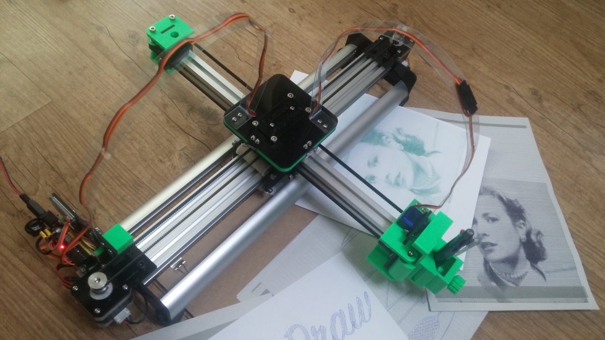
 Personalize and sign certificates
 Formal invitations
 Work with small and irregularly shaped paper
 Party invitation with fine-point markers
 Printing text with a fountain pen
 with pen") Stipple drawing with pen
Stipple drawing with pen Precision drawing with rollerball pens
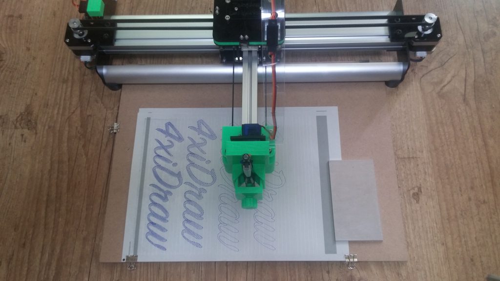 Large writing with permanent marker


 with pen")


 Printable area: US Letter + A4
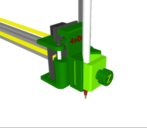 Pen holder: Vertical configuration
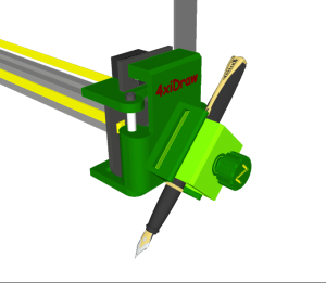 Pen holder: 45-degree configuration
 Pick the right angle for each writing implement


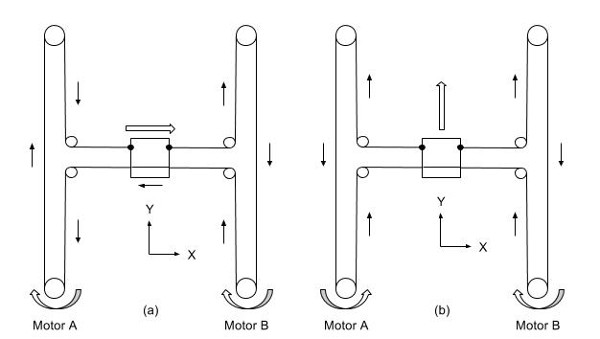
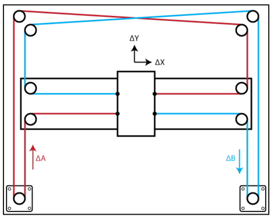


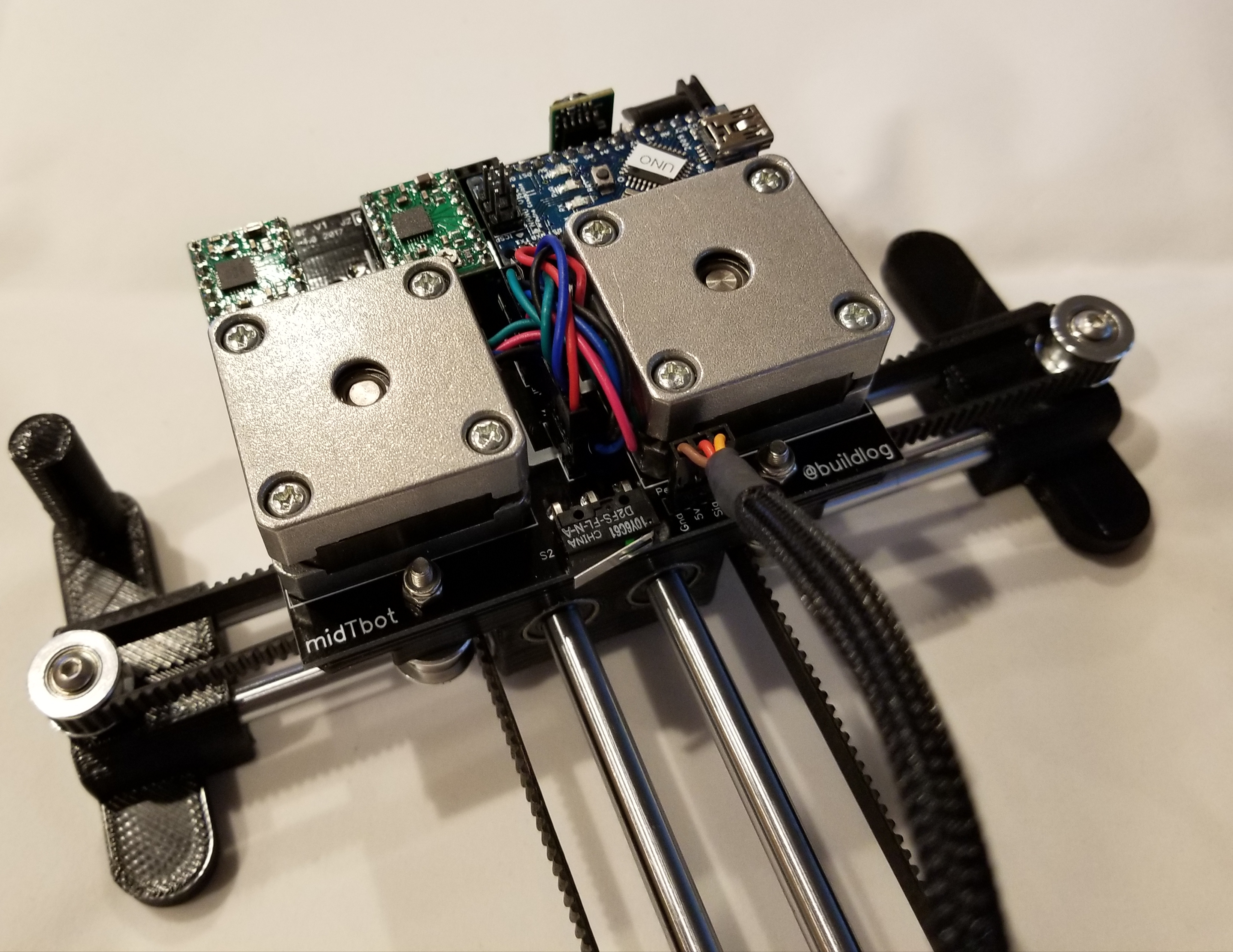

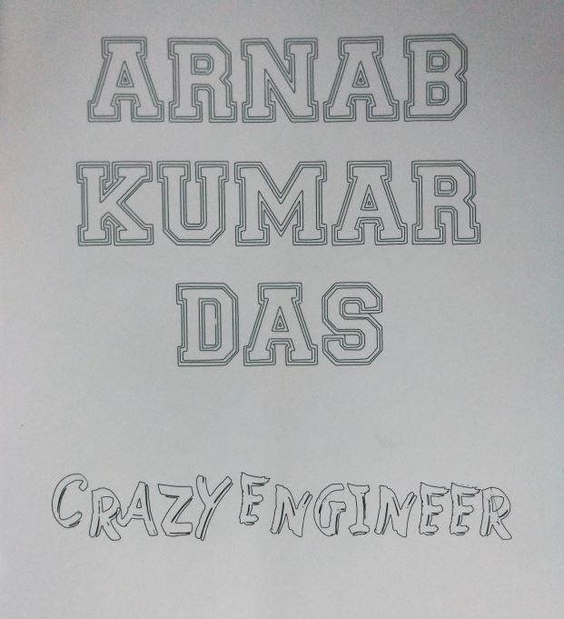

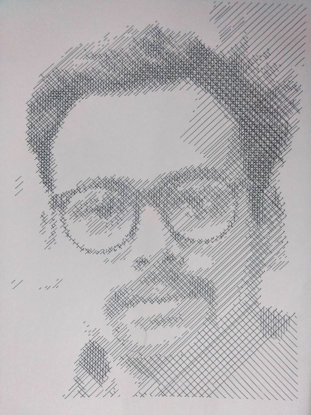
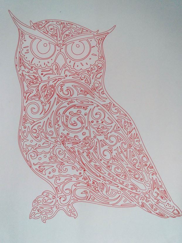
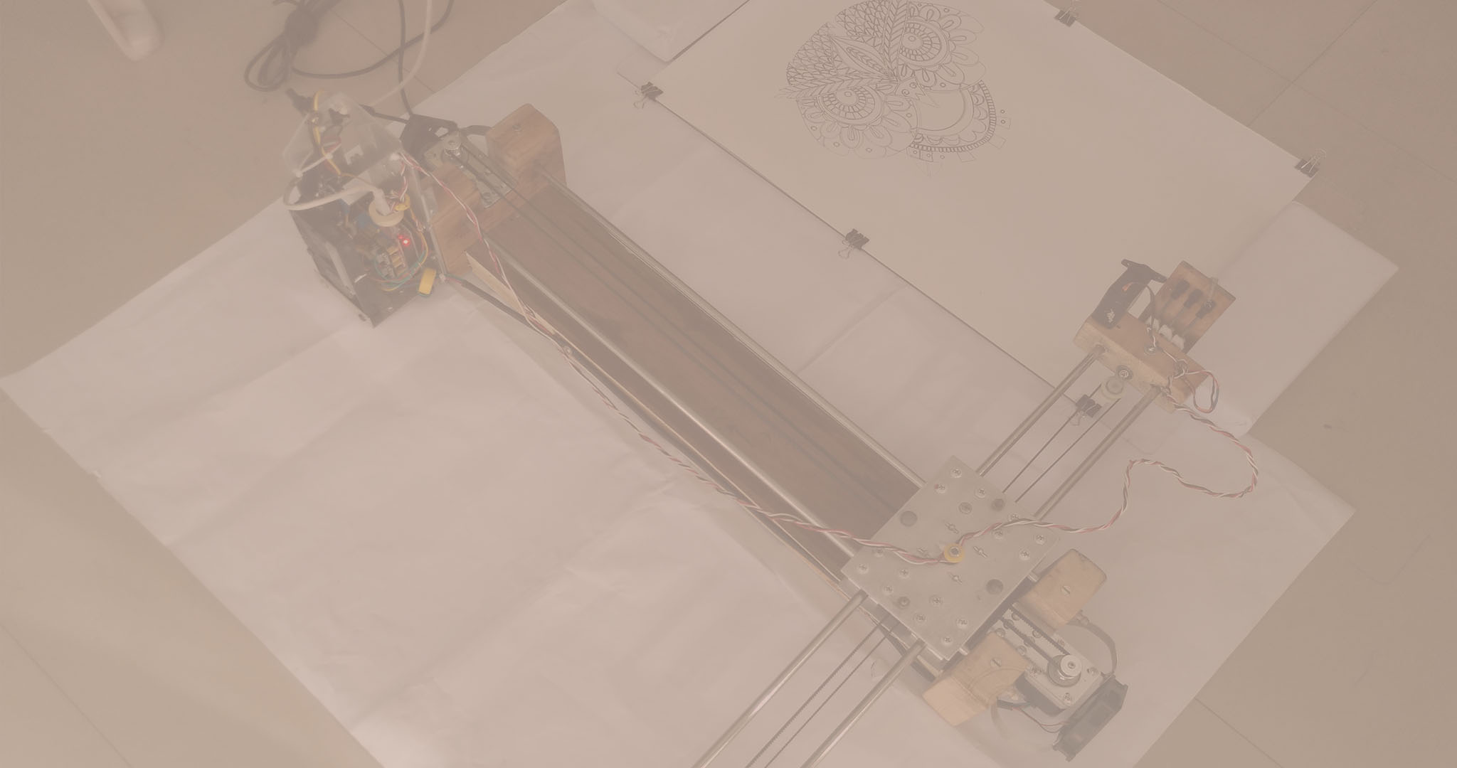

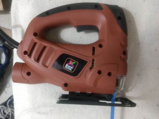
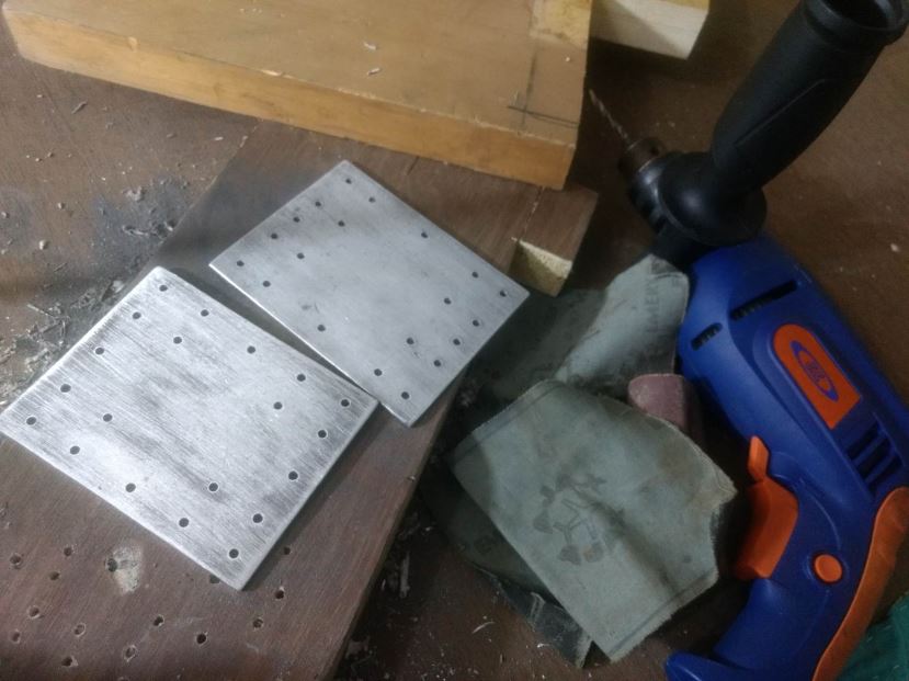
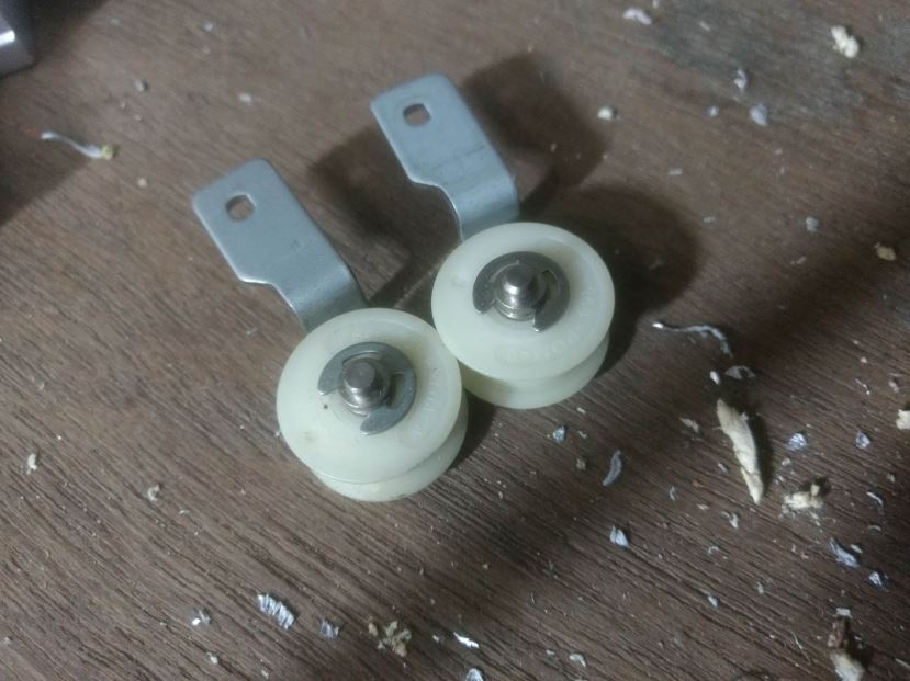
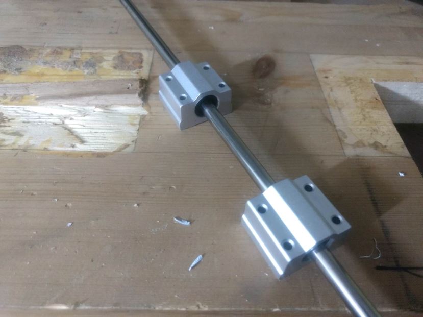
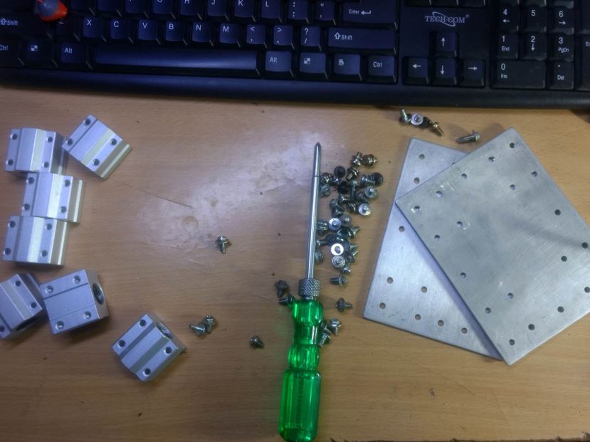
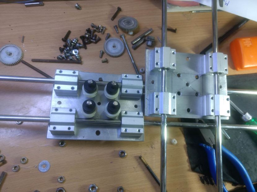
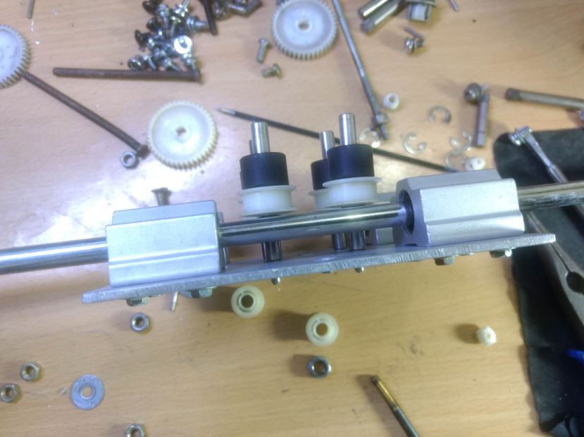
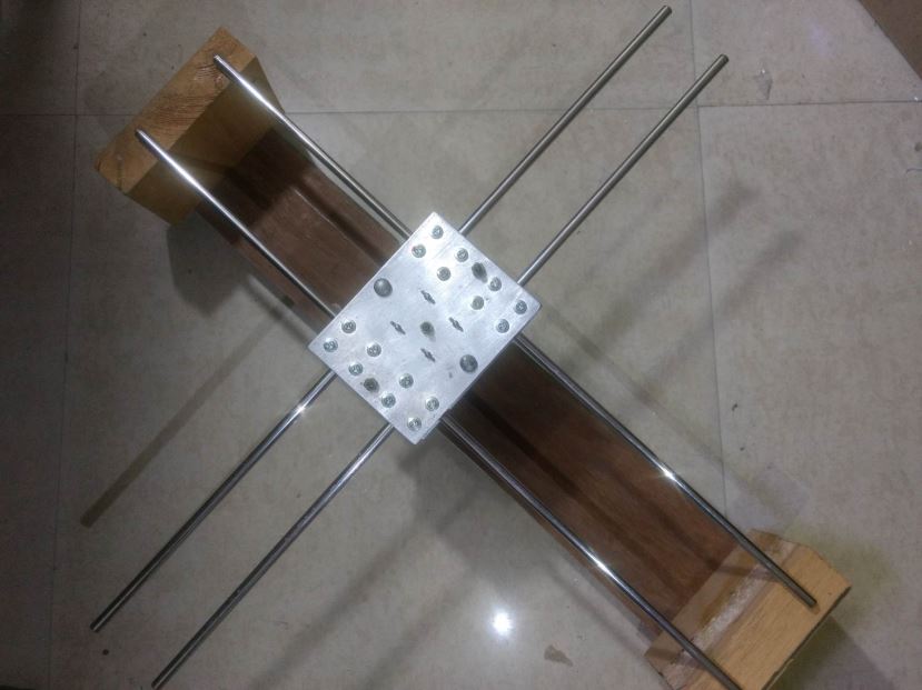
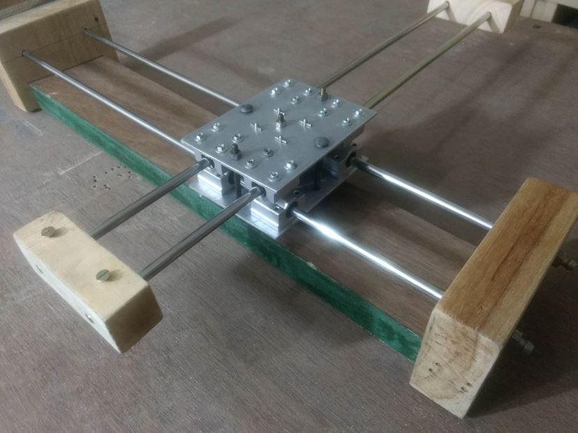
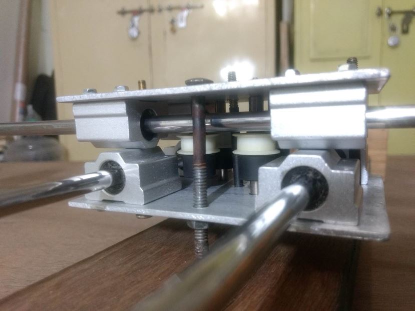
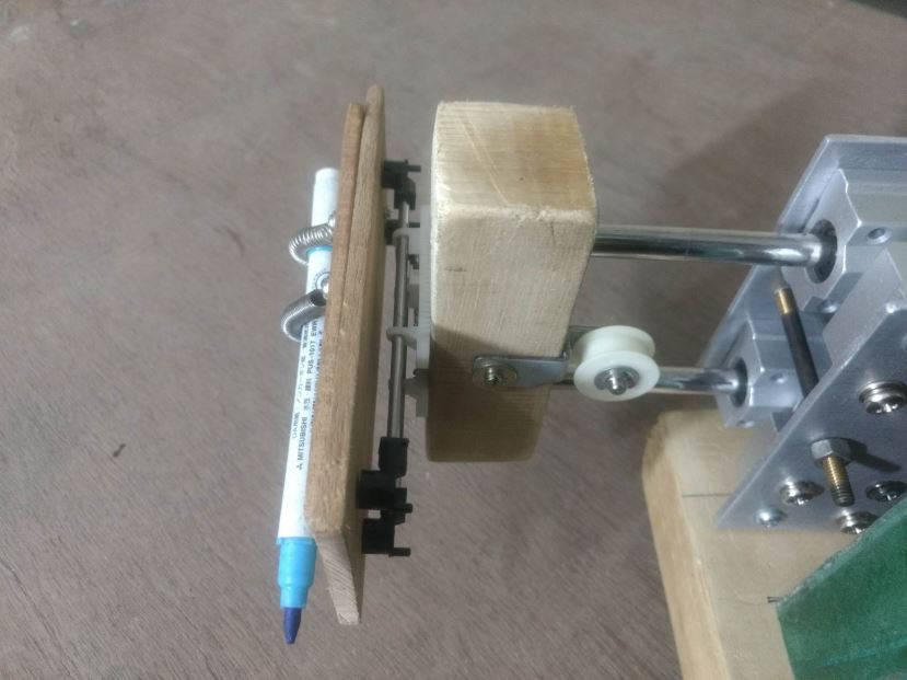
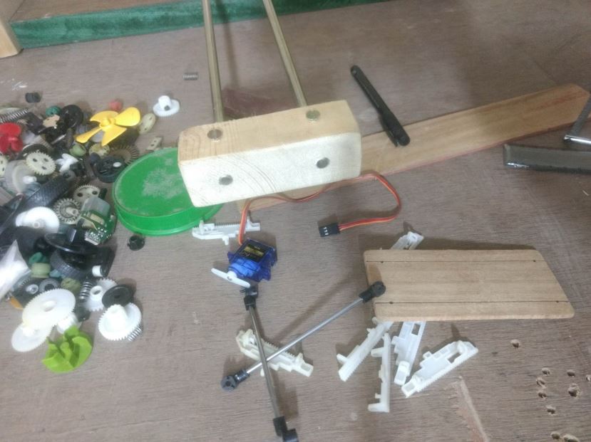
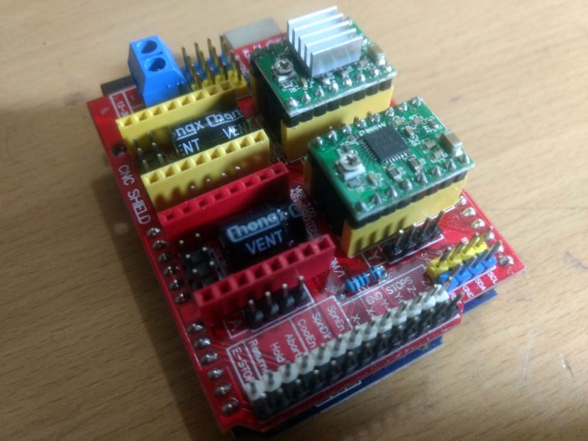
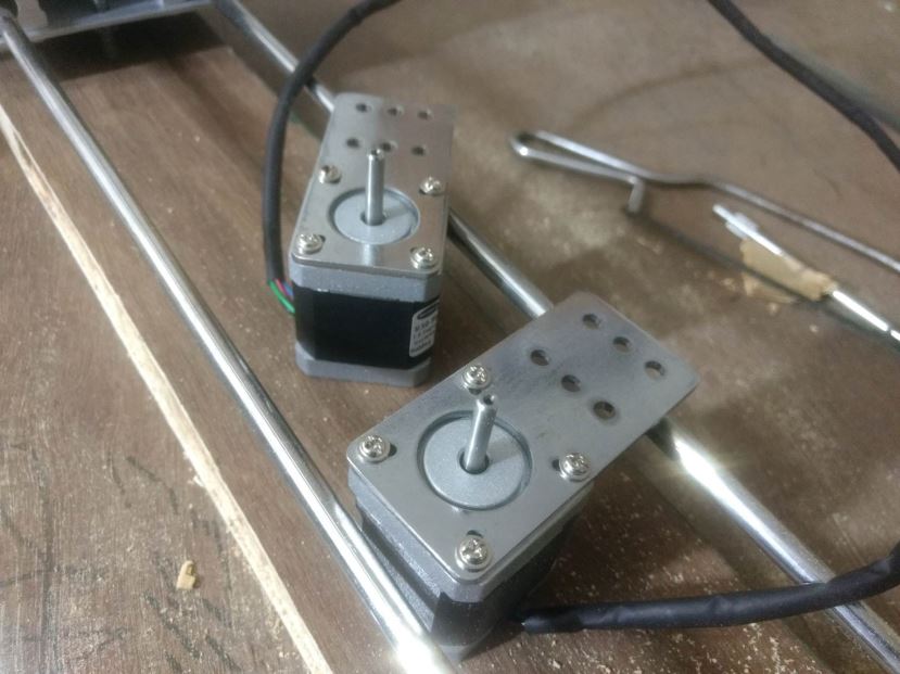
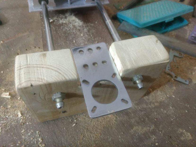
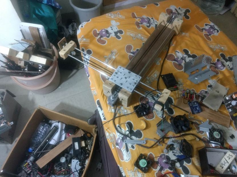
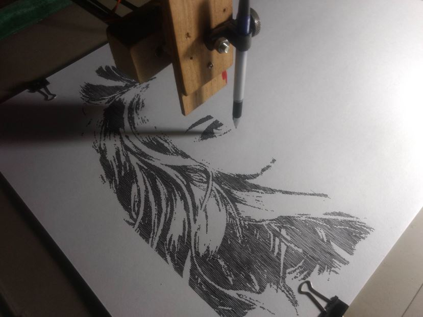
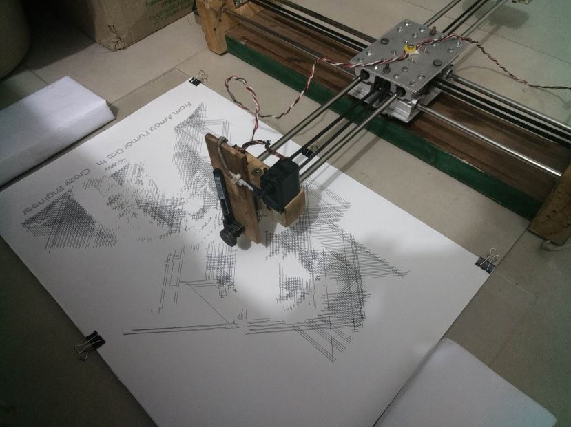
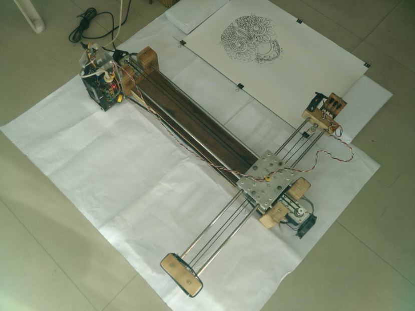
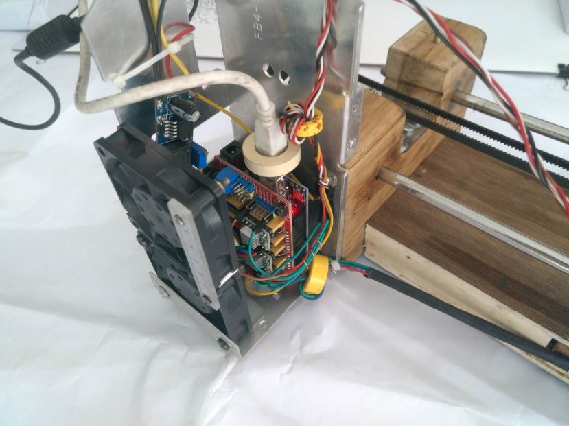
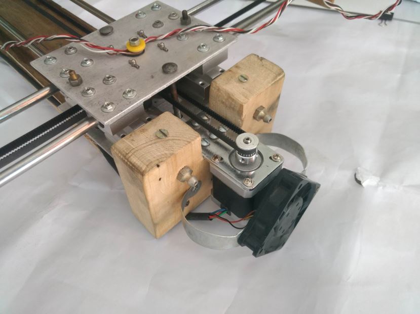
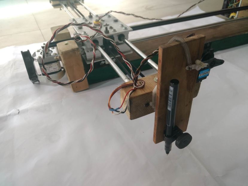
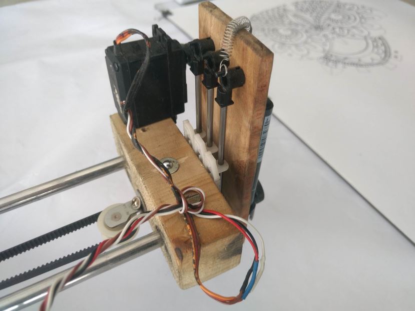
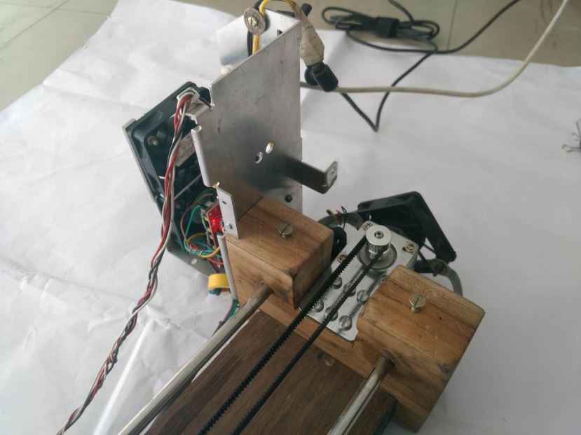
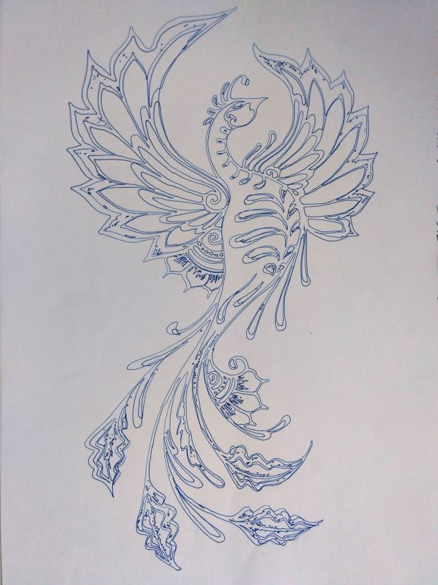
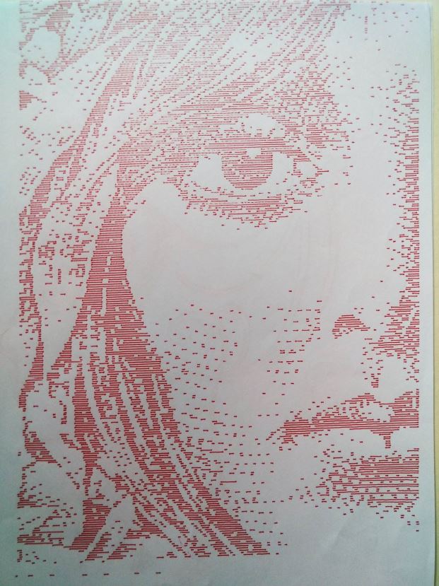

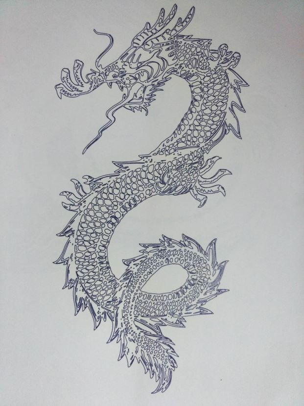
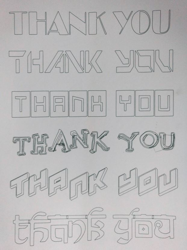

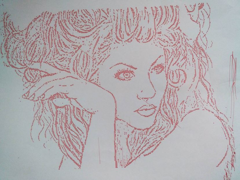
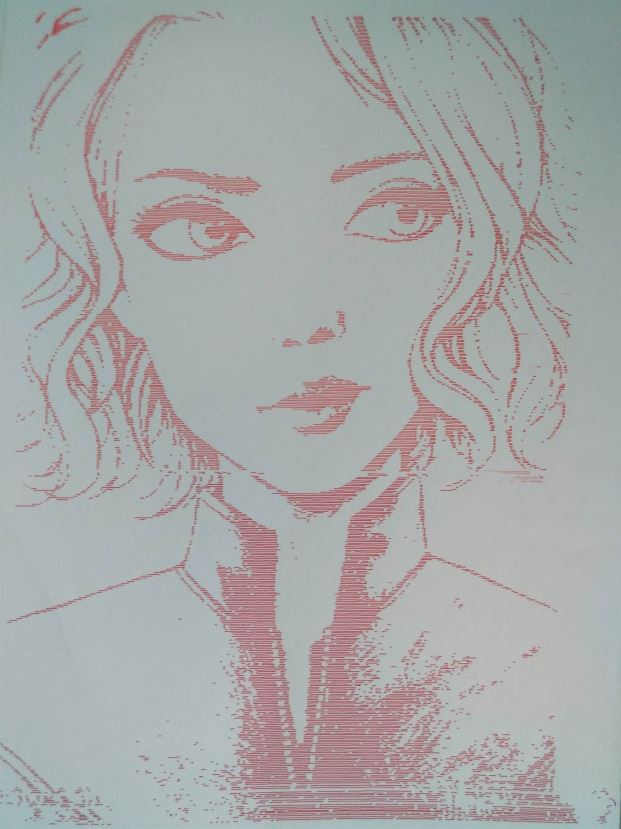
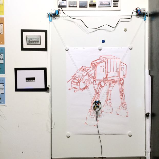
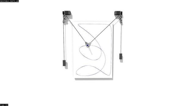
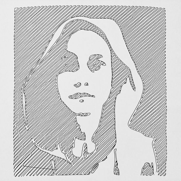
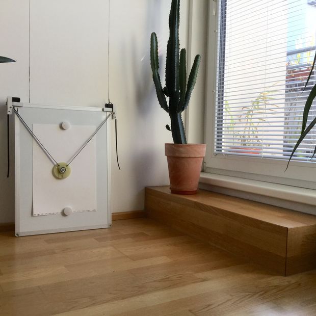
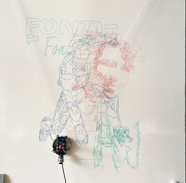
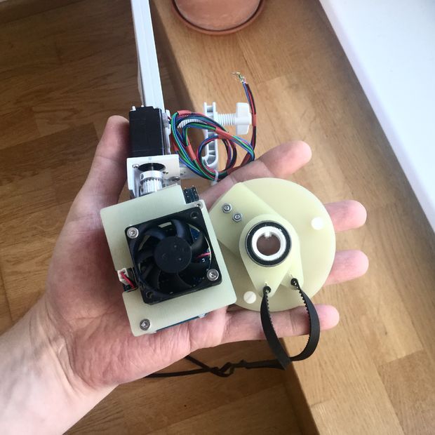
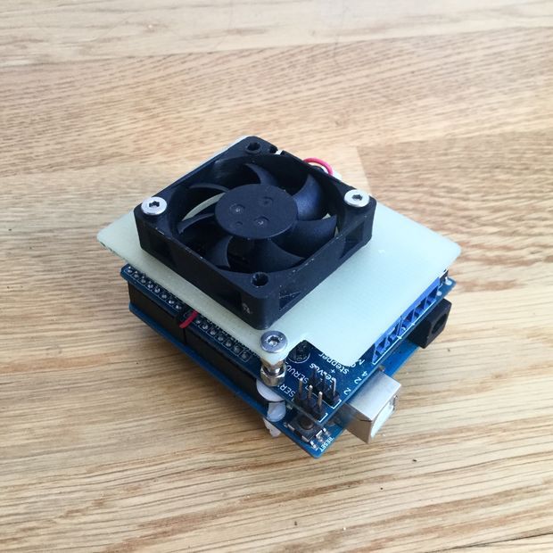
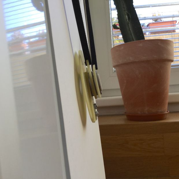
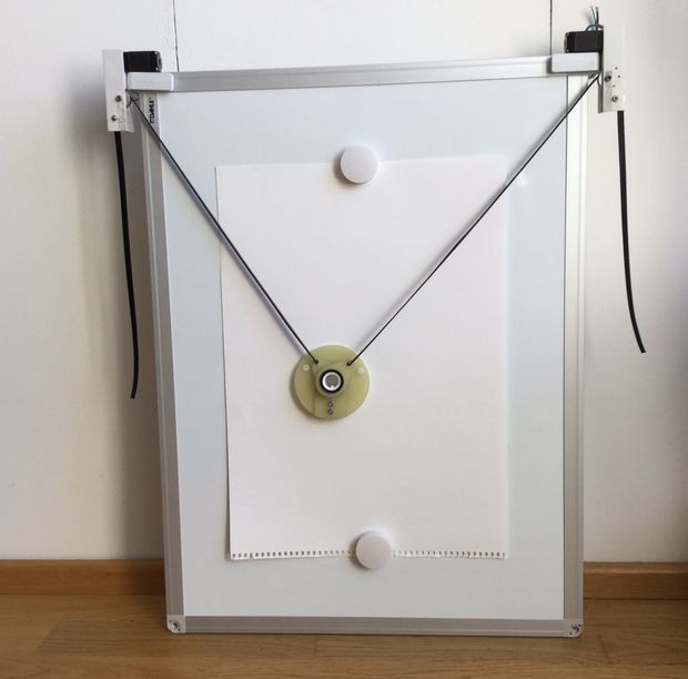
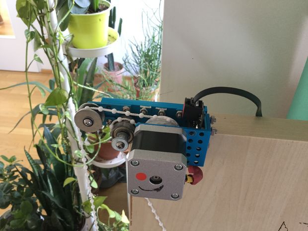
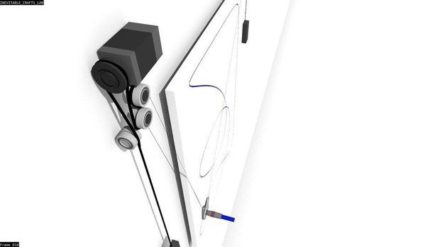
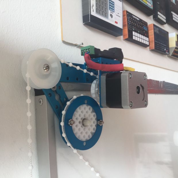
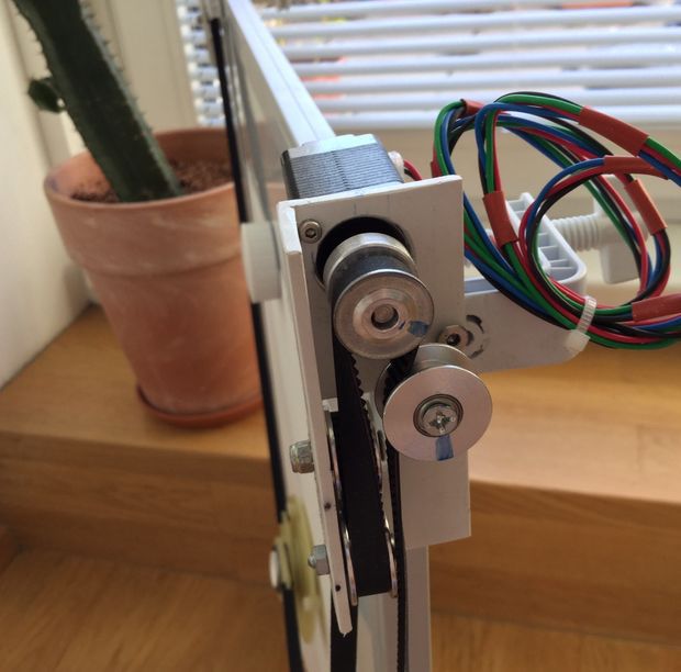
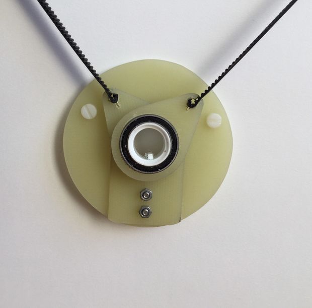
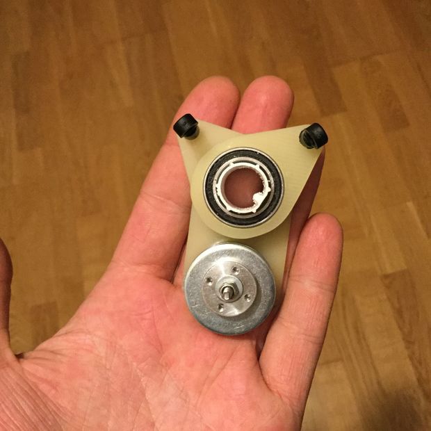
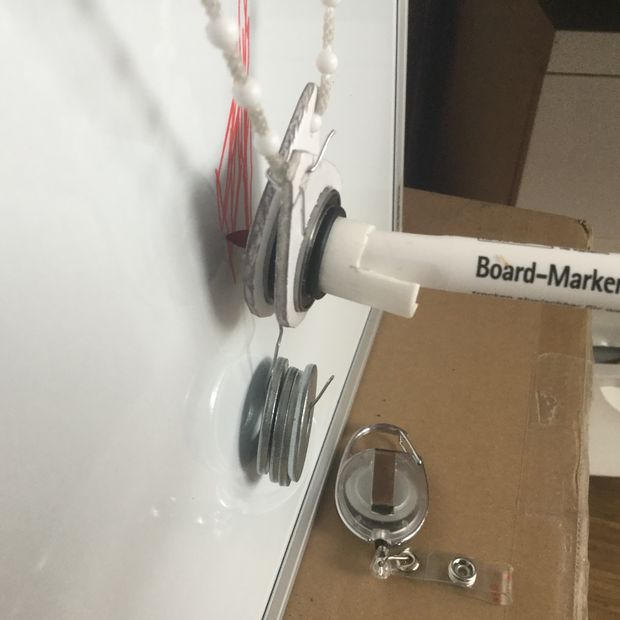
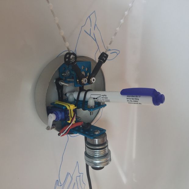
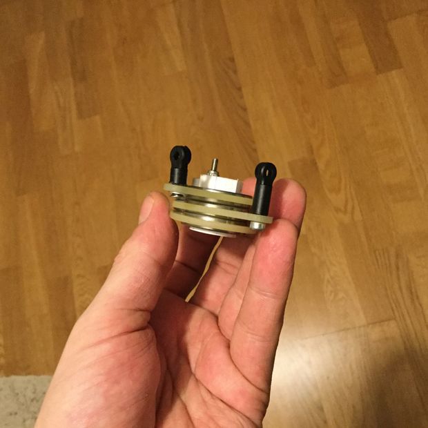

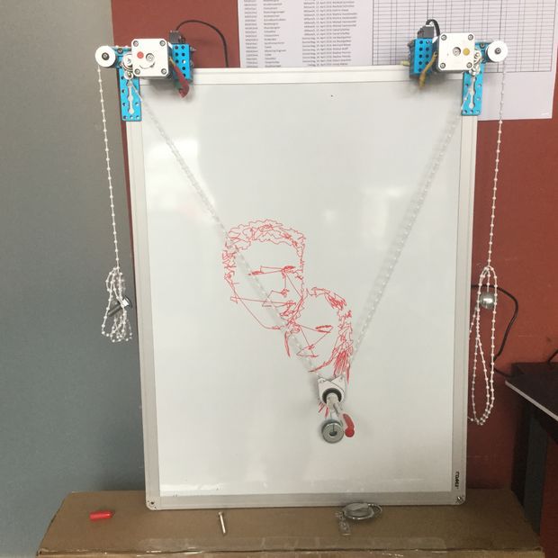
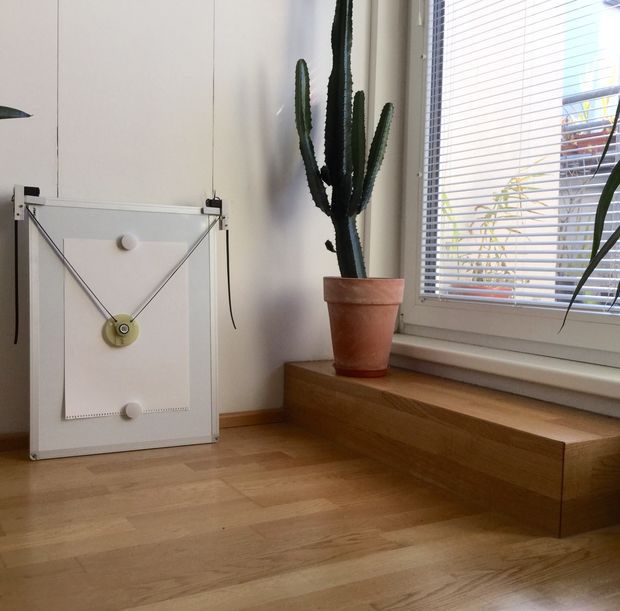
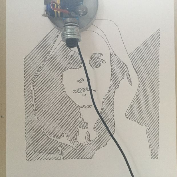
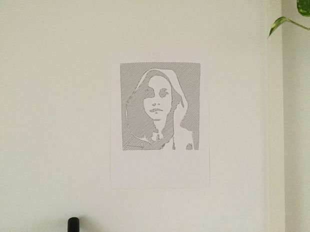
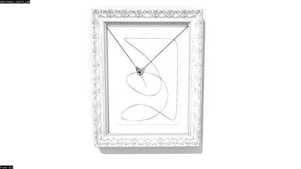

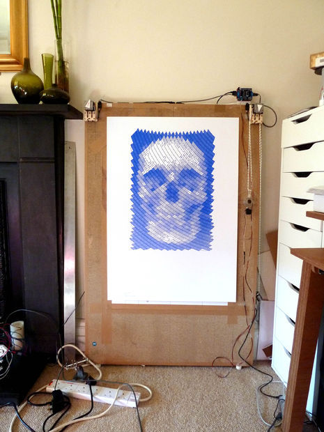
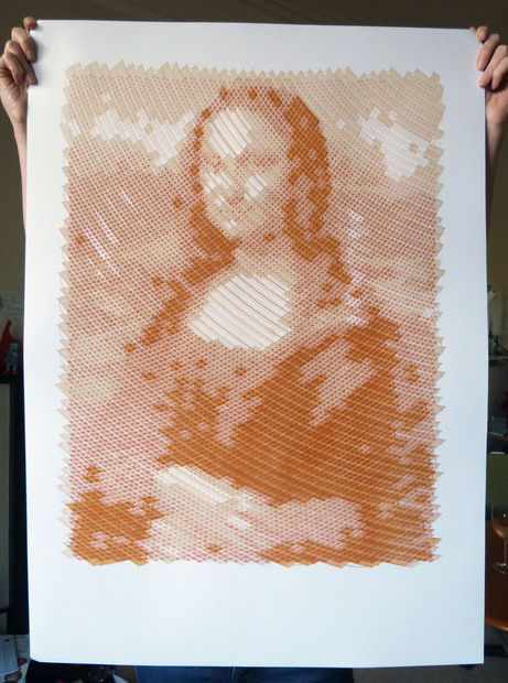
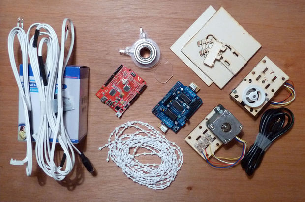
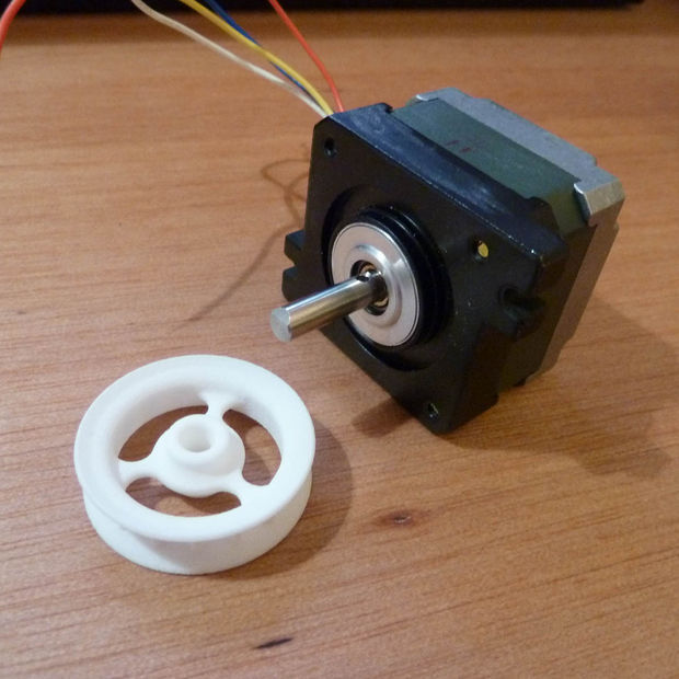
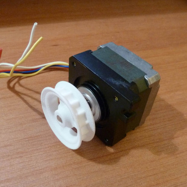

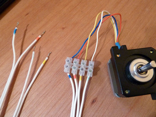
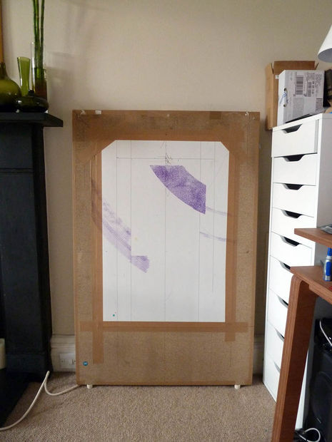
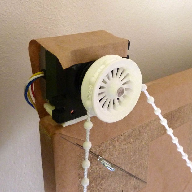
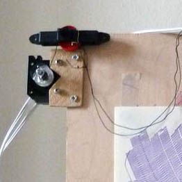
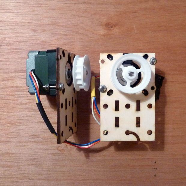
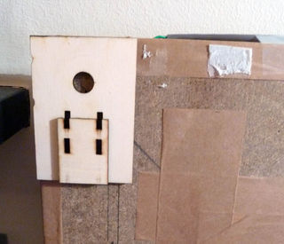
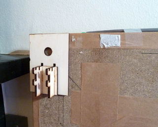
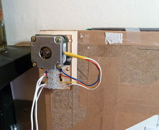
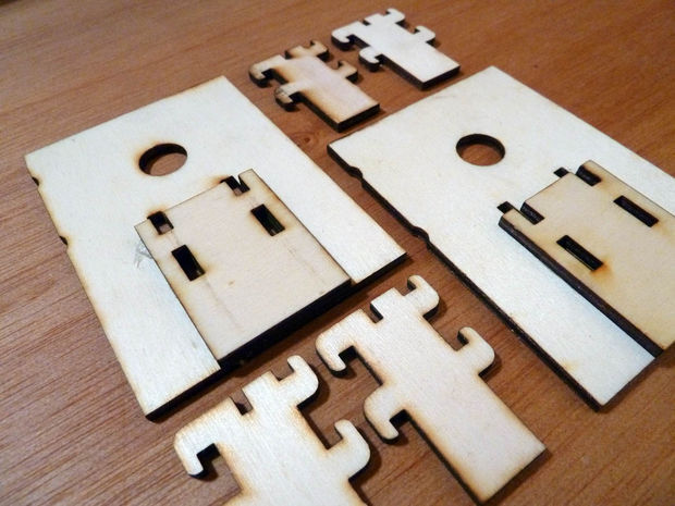

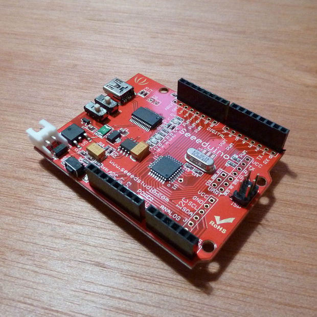
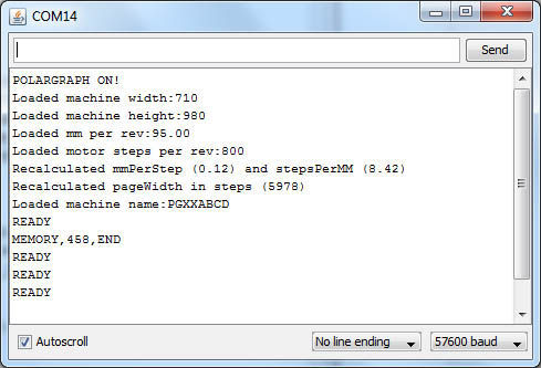
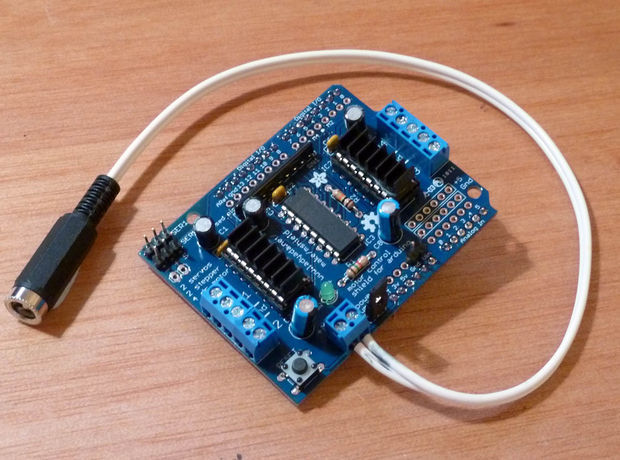
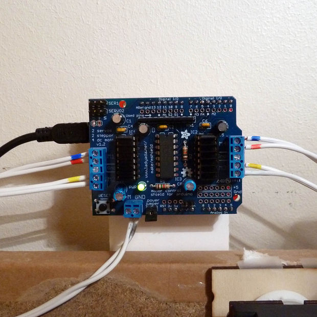
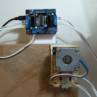
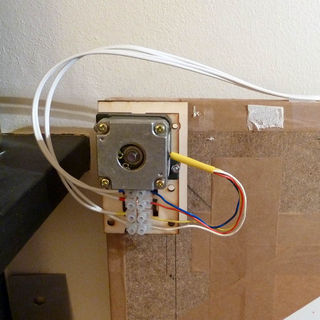
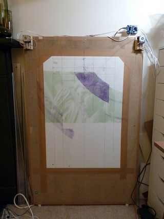
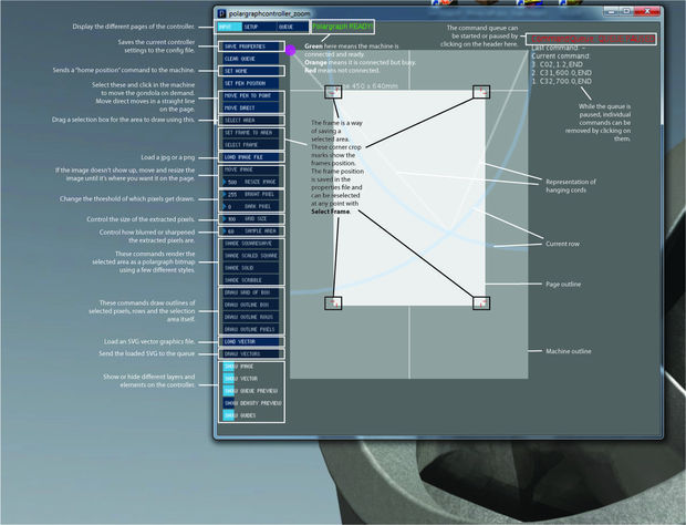
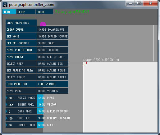
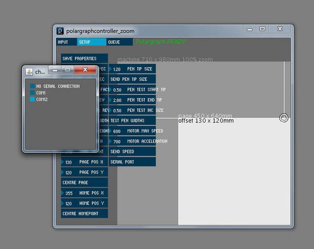
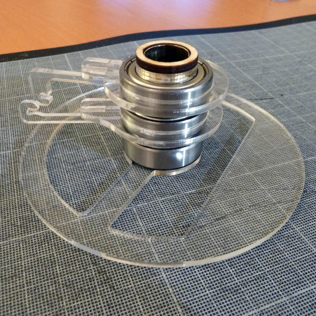
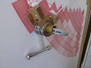
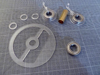
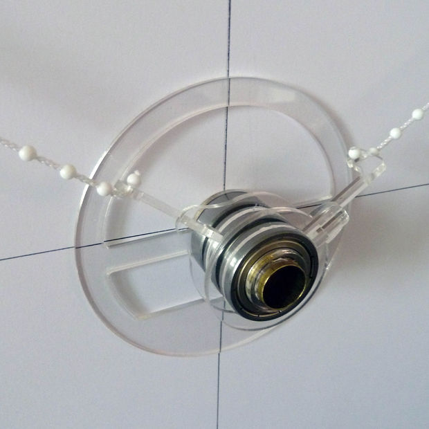
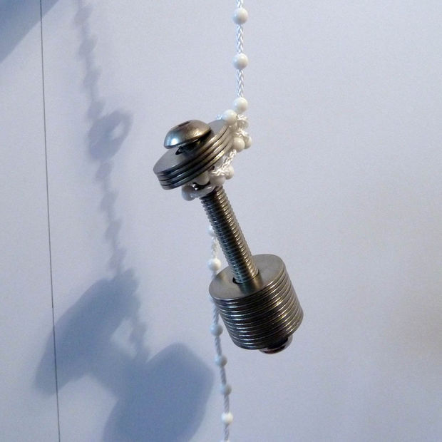
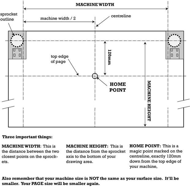
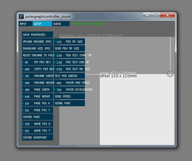
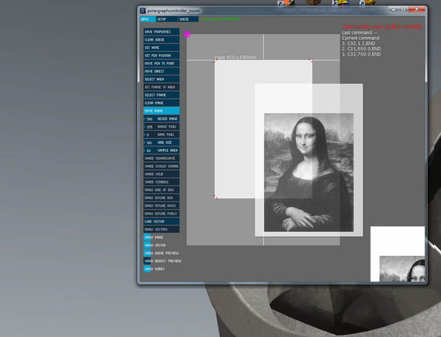
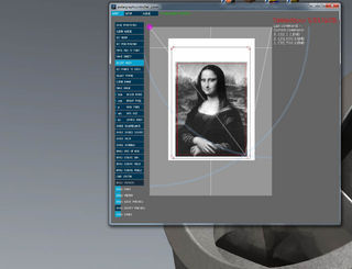
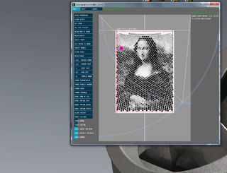
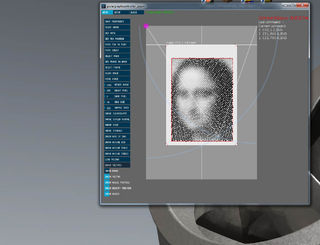
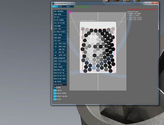
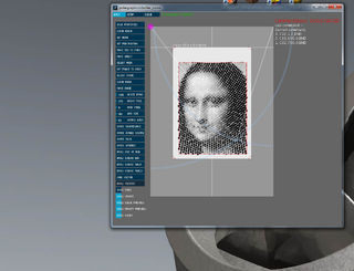
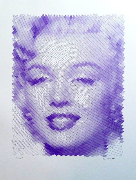
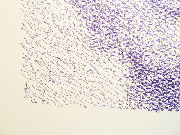
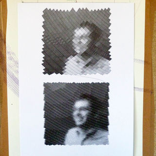
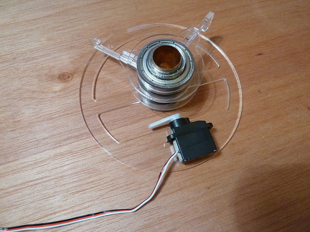
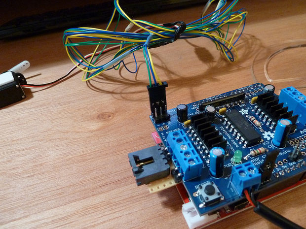
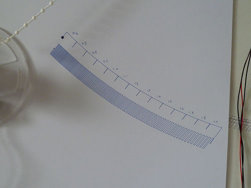
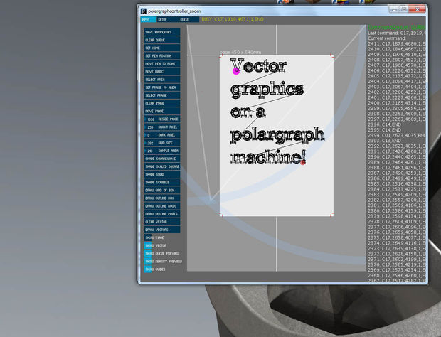
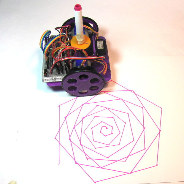

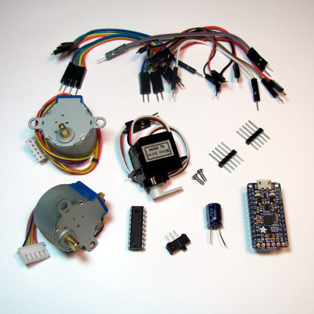
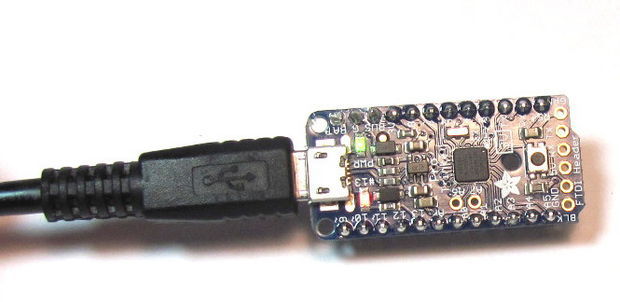
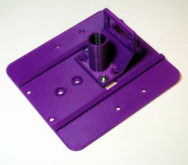
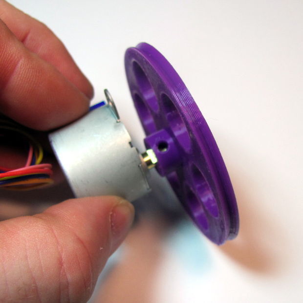
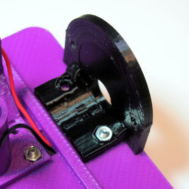
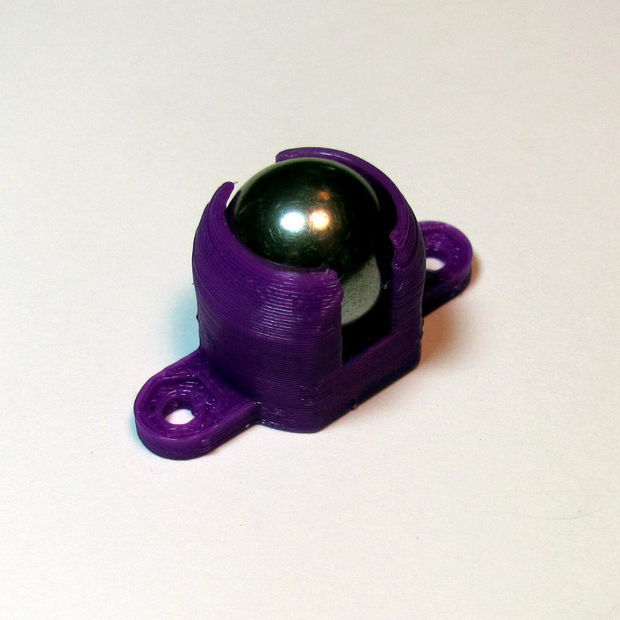
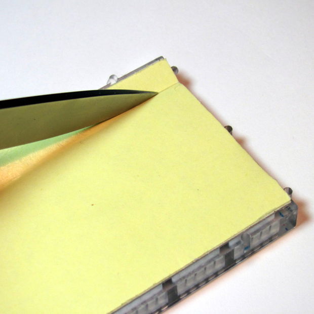
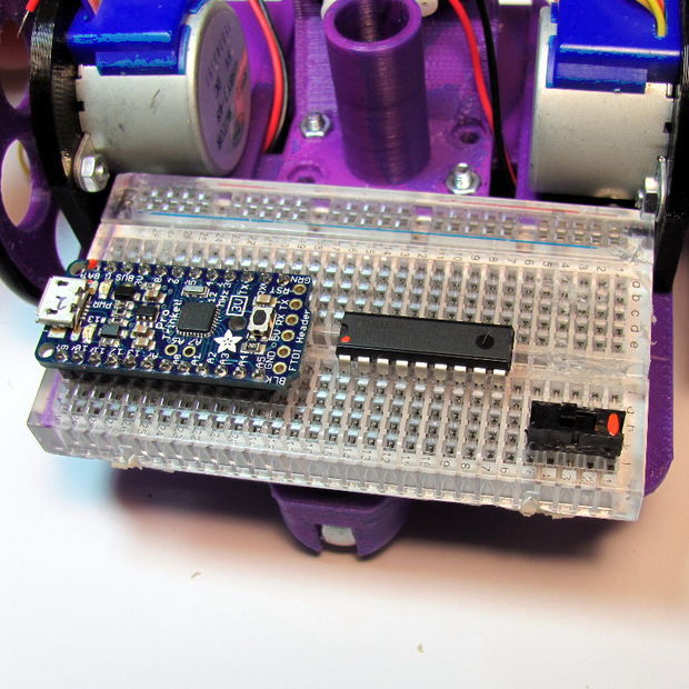
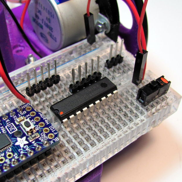
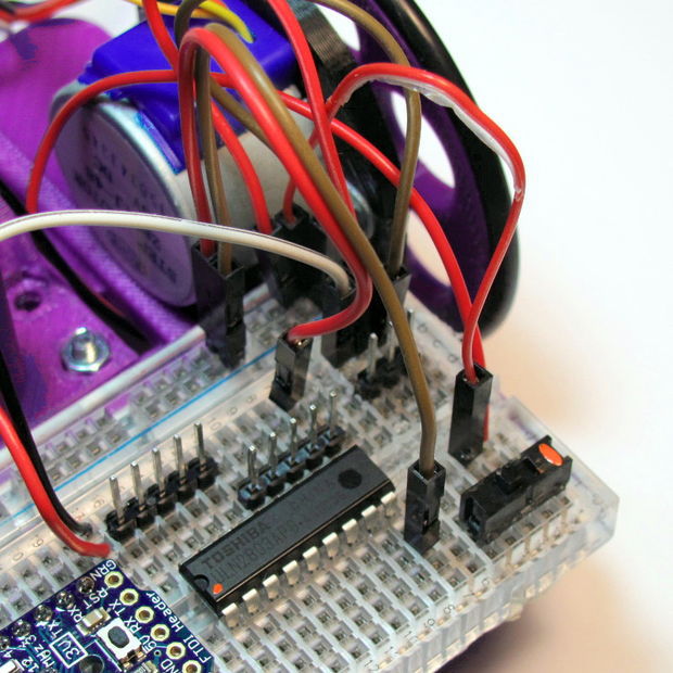
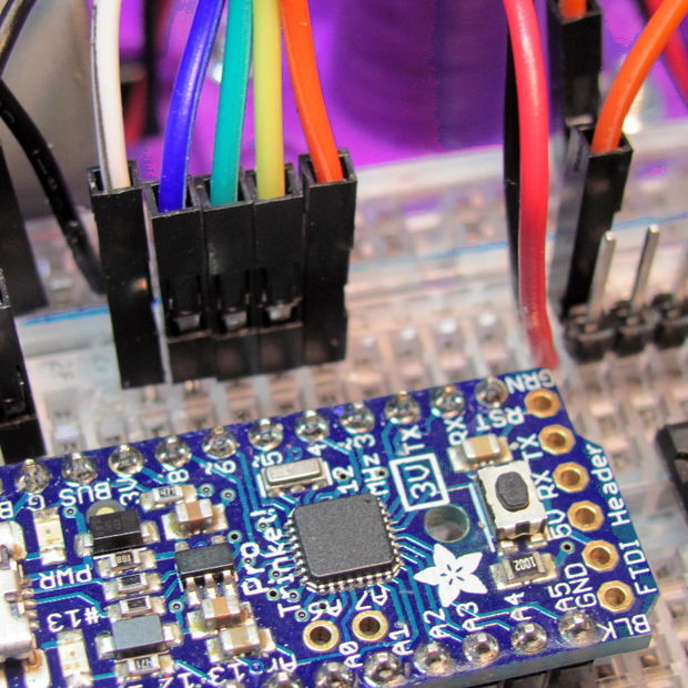
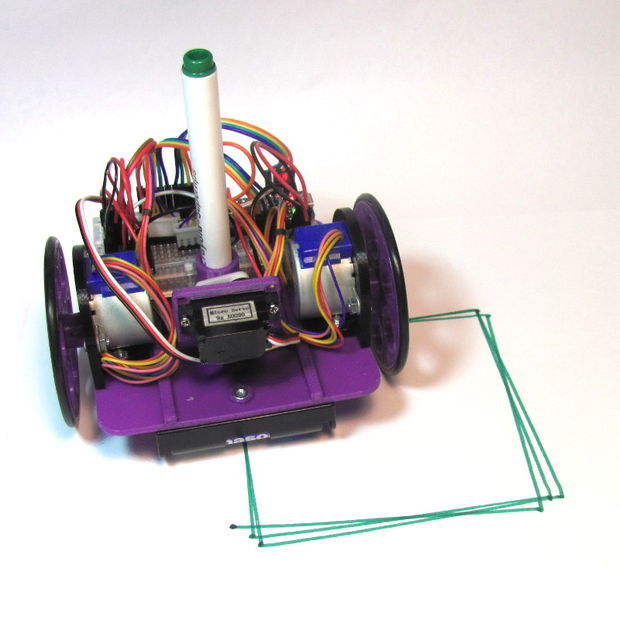
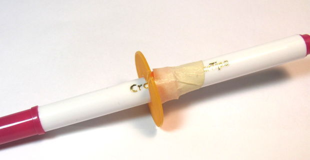

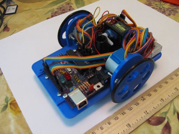