28BYJ-48 Stepper Motor

Stepper Motor  is a motor controlled by a series of electromagnetic coils. The center shaft has a series of magnets mounted on it, and the coils surrounding the shaft are alternately given current or not, creating magnetic fields which repulse or attract the magnets on the shaft, causing the motor to rotate.

This design allows for very precious control of the motor,There are two basic types of stepper motors, unipolar steppers and bipolar steppers .

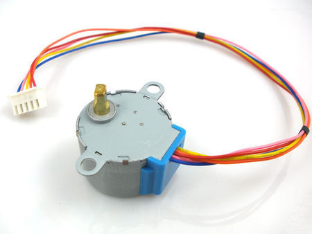
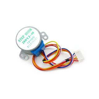
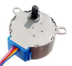
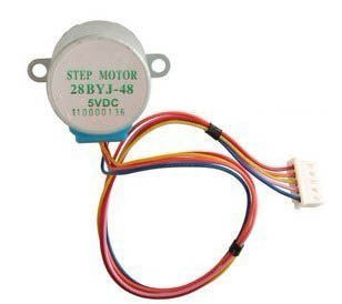
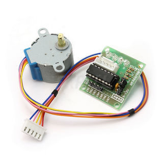
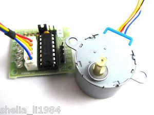
In This instructable , I will talk about an Unipolar Stepper Motor 28-BYJ48 .

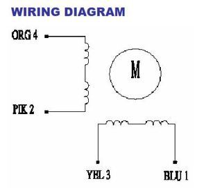
The unipolar stepper motor has five or six wires and four coils (actually two coils divided by center connections on each coil). The center connections of the coils are tied together and used as the power connection. They are called unipolar steppers because power always comes in on this one pole.

Step 1: Specification , Motor Driver

There are many Types of Drivers , L293 , ULN2003 , A3967SLB , And More ,
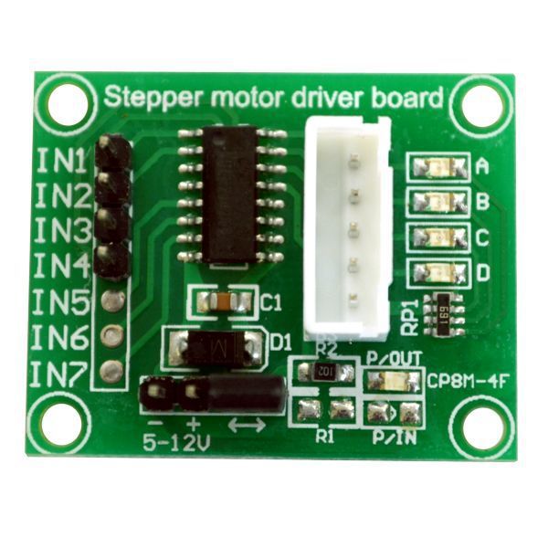
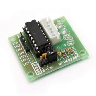
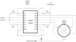
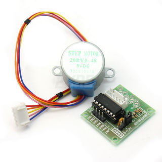
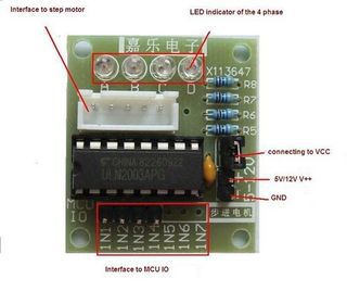
The 28-BYJ48 Even comes with Breakout using ULN2003 As a Motor driver chip .
Specification for this Motor  ” And you can download datasheet from the attachment “Rated voltage : 5VDC
Number of Phase 4
Speed Variation Ratio 1/64
Stride Angle 5.625° /64
Frequency 100Hz
DC resistance 50Ω±7%(25℃)
Idle In-traction Frequency > 600Hz
Idle Out-traction Frequency > 1000Hz
In-traction Torque >34.3mN.m(120Hz)
Self-positioning Torque >34.3mN.m
Friction torque 600-1200 gf.cm
Pull in torque 300 gf.cm
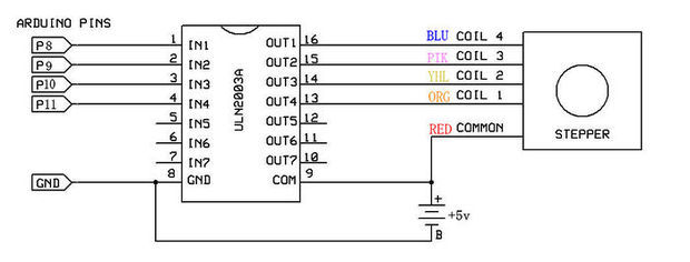
Insulation grade Aand the schematics of  This breakout shown like the Pictures on the attachment
Note that if you want to use L293 Instead of ULN2003 , You will need to leave Red wire No connection.
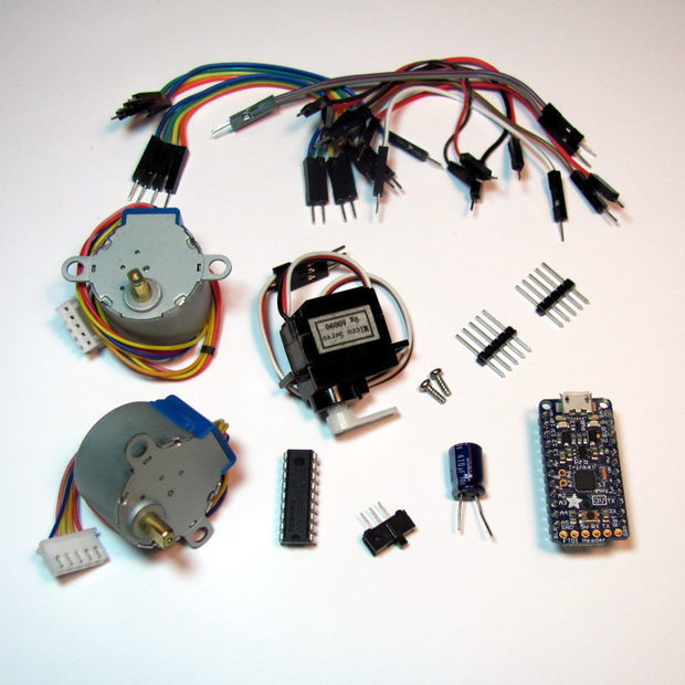
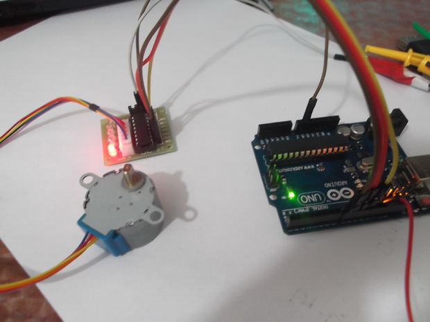
Materials :

you will need :

1) Arduino Board .
2) BYJ48 Stepper Motor 5v
3) ULN2003 Moror driver Module
4) Jumper .
5) 5v voltage source  “Optional” .

Step 2: Arduino Code .

\

The Arduino IDE Support a Library for Stepper Motor , Very Easy to use , After Connect Motor with arduino You can Upload the Sketch on to the arduino .

But …

You must take something  in consider :

This Motor has a Gear ratio of 64 , and Stride Angle 5.625°  so this motor has a 4096 Steps .

 steps = Number of steps in One Revolution  * Gear ratio   .

steps= (360°/5.625°)*64″Gear ratio” = 64 * 64 =4096 . this value will substitute it on The arduino Sketch

For adafruit Stepper Motor , the Stride Angle 7.5° and Gear ratio is 16 , So number of steps in 1 Revolution is :

steps in One Revolution  = 360 / 7.5 = 48   .

steps= 48 * 16 = 768

That’s will be different depend on what motor you are using , So check The Datasheet for Your stepper Motor to calibrate this values

28-BYJ48 Motor Datasheet .

Motor Driver ULN2003 BreakOut Connected To Arduino From IN1 – IN4 To D8 – D11 Respectively

To Power you Motor ,  Recommanded to use external Power Supply with 5V-500mA  at least , Don’t power it directly from arduino Board 5V .

Step 3: Library Direction Issue … And how to fix it .

When You Upload the sketch to the arduino , The Motor will Be rotate in  one direction By type the command :

step(steps);

So you must Put the Number of step to turn the motor .

The reference  said You can put the positive value to turn one direction, negative to turn the other.

If that’s  OK With Your stepper Motor , You  don’t need to read the following .

If Not , Your Motor turn to same direction even you Put the steps Positive Value or negative , What is the issue ?

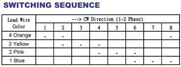
This Motor need to operate as the Table on the attachment .

the arduino Stepper Library need to modify to match this requirement .

I wrote a code which is allow to this motor to Move clockwise and counter clock wise

Code in the next step :

Step 4: Modify Code

the final code for this Stepper motor :

/*
BYJ48 Stepper motor code
Connect :
IN1 >> D8
IN2 >> D9
IN3 >> D10
IN4 >> D11
VCC … 5V Prefer to use external 5V Source
Gnd
written By :Mohannad Rawashdeh
http://www.instructables.com/member/Mohannad+Rawashdeh/
28/9/2013
*/

#define IN1  8
#define IN2  9
#define IN3  10
#define IN4  11
int Steps = 0;
boolean Direction = true;// gre
unsigned long last_time;
unsigned long currentMillis ;
int steps_left=4095;
long time;
void setup()
{
Serial.begin(115200);
pinMode(IN1, OUTPUT);
pinMode(IN2, OUTPUT);
pinMode(IN3, OUTPUT);
pinMode(IN4, OUTPUT);
// delay(1000);

}
void loop()
{
while(steps_left>0){
currentMillis = micros();
if(currentMillis-last_time>=1000){
stepper(1);
time=time+micros()-last_time;
last_time=micros();
steps_left–;
}
}
Serial.println(time);
Serial.println(“Wait…!”);
delay(2000);
Direction=!Direction;
steps_left=4095;
}

void stepper(int xw){
for (int x=0;x<xw;x++){
switch(Steps){
case 0:
digitalWrite(IN1, LOW);
digitalWrite(IN2, LOW);
digitalWrite(IN3, LOW);
digitalWrite(IN4, HIGH);
break;
case 1:
digitalWrite(IN1, LOW);
digitalWrite(IN2, LOW);
digitalWrite(IN3, HIGH);
digitalWrite(IN4, HIGH);
break;
case 2:
digitalWrite(IN1, LOW);
digitalWrite(IN2, LOW);
digitalWrite(IN3, HIGH);
digitalWrite(IN4, LOW);
break;
case 3:
digitalWrite(IN1, LOW);
digitalWrite(IN2, HIGH);
digitalWrite(IN3, HIGH);
digitalWrite(IN4, LOW);
break;
case 4:
digitalWrite(IN1, LOW);
digitalWrite(IN2, HIGH);
digitalWrite(IN3, LOW);
digitalWrite(IN4, LOW);
break;
case 5:
digitalWrite(IN1, HIGH);
digitalWrite(IN2, HIGH);
digitalWrite(IN3, LOW);
digitalWrite(IN4, LOW);
break;
case 6:
digitalWrite(IN1, HIGH);
digitalWrite(IN2, LOW);
digitalWrite(IN3, LOW);
digitalWrite(IN4, LOW);
break;
case 7:
digitalWrite(IN1, HIGH);
digitalWrite(IN2, LOW);
digitalWrite(IN3, LOW);
digitalWrite(IN4, HIGH);
break;
default:
digitalWrite(IN1, LOW);
digitalWrite(IN2, LOW);
digitalWrite(IN3, LOW);
digitalWrite(IN4, LOW);
break;
}
SetDirection();
}
}
void SetDirection(){
if(Direction==1){ Steps++;}
if(Direction==0){ Steps–; }
if(Steps>7){Steps=0;}
if(Steps<0){Steps=7; }
}

Low-Cost, Arduino-Compatible Drawing Robot

I designed this project for a 10-hour workshop for ChickTech.org whose goal is to introduce teenage women to STEM topics. The goals for this project were:

  • Easy to build.
  • Easy to program.
  • Did something interesting.
  • Low-cost so participants could take it home and continue to learn.

With those goals in mind, here were a couple of the design choices:

  • Arduino compatible for ease of programming.
  • 4xAA battery power for cost and availability.
  • Stepper motors for accurate motion.
  • 3D Printed for ease of customization.
  • Pen plotting with Turtle graphics for interesting output.
  • Open Source so you could make one of your own!

Here is the robot that came closest to what I wanted to do: http://mirobot.io. I don’t have a laser cutter and shipping from England was prohibitive. I do have a 3D printer, so I guess you can see where this is going . . .

Don’t let the lack of a 3D printer deter you. You can locate local hobbyists willing to help you out at https://www.3dhubs.com/.

It took a lot of work, but I’m please with how it turned out. And, I learned quite a bit in the process. Let me know what you think!

Step 1: Parts

There are a number of ways to power, drive, and control robots. You may have different parts on hand that will work, but these are the ones I’ve tried and found to work well:

Electronics:

*Note: See the last step for a discussion on using regular Arduino or Raspberry Pi boards.

Hardware:

3D-Printed Parts (check out www.3dhubs.com if you don’t have access to a printer):

Tools and Supplies:

  • Phillips screw driver
  • Hot glue gun
  • Digital multi-meter
  • Sharp knife
  • Crayola colored markers

Step 2: Flash the Firmware

Before we get too far into construction, lets load the test firmware on to the microcontroller. The test program just draws for boxes so we can check for proper direction and dimension.

To talk to the Trinket Pro, you are going to need:

  1. Driver from https://learn.adafruit.com/introducing-pro-trinket…
  2. Arduino software from https://learn.adafruit.com/introducing-pro-trinket…

Lady Ada and the Adafruit team have created a far better set of instructions in the links above than I can provide. Please use them if you are stuck.

Note: The one trick that makes the Trinket different from regular Arduino is that you have to reset the board before uploading the sketch.

Step 3: Pen Holder and Battery Holders

  1. Install the Pen Holder with the Servo Bracket on the shorter side of the chassis (Image 1).
  2. Insert the nuts on the top side of the chassis (Image 2)
  3. Attach the battery holders on the bottom of the chassis using 3Mx6mm flat-head screws (Images 3 & 4).
  4. Thread the battery leads through the rectangular cable runs (Image 4 & 5).
  5. Repeat for the other battery holder.

Note: Unless specified, the remainder of the screws are 3Mx8mm pan head srews.

Step 4: Wheels

  1. Test fit your wheel to the stepper shaft (Image 1).
    1. If it is too tight, you can heat the wheel hub with a hair drier or hot air gun and then insert the shaft.
    2. If it is too loose, you can use a 3Mx8mm screw to hold it against the flat of the shaft (Image 2).
    3. If you are a perfectionist, you can calibrate your printer and get it just right.
  2. Place the o-ring around the rim of the wheel (Image 3 & 4).
  3. Repeat for the other wheel.

Step 5: Stepper Brackets

  1. Insert a nut into the stepper bracket and attach them to the top of the chassis with a screw (Image 1).
  2. Insert the stepper into the bracket and attach with screws and nuts.
  3. Repeat for the other bracket.

Step 6: Caster

  1. Insert the ball bearing into the caster.
    • Do not force it in or it will break. Use a hair-drier or hot air gun to soften the material if needed.
  2. Attach the caster to the bottom side of the chassis in front of the battery holder.

Step 7: Breadboard

  1. Remove one of the power rails using a sharp knife, cutting through the bottom adhesive (Image 1).
  2. Holding the breadboard over the chassis rails, mark where they intersect the edge (Image 2).
  3. Using a straight edge (like the removed power rail), mark the lines and cut through the backing (Image 3).
  4. Place the breadboard on the chassis with the rails touching the exposed adhesive (Image 4).

Step 8: Power

  1. Place the microcontroller, darlington driver, and power switch on to the bread board (Image 1).
    • I’ve added orange dots for visibility to mark the following:
      • Pin 1 of the darlington driver.
      • The battery pin of the microtroller.
      • The power switch “on” position.
  2. With the right-hand battery leads:
    1. Connect the red line to the first pin of the power switch (Image 2).
    2. Connect the black lead to an empty row between the microcontroller and the darlington chip (Image 2).
  3. With the left-hand battery leads:
    1. Connect the red line to the same row as the black lead of the other battery (Image 3).
    2. Connect the black line to the negative rail of the breadboard (Image 3).
  4. Connect power to the microcontroller:
    1. Red jumper from positive rail to the battery pin (orange dot, Image 4).
    2. Black jumper from the negative rail to the pin marked “G” (Image 4).
  5. Install batteries and switch the power on. You should see the green and red lights of the controller come on (Image 5).

Troubleshooting: If the microcontroller lights do not come on, immediately turn the power off and troubleshoot:

  1. Batteries installed in the correct orientation?
  2. Double check battery leads positioning.
  3. Double check switch leads positioning.
  4. Use a multi-meter to check voltages of batteries.
  5. Use multi-meter to check power rail voltages.

Step 9: Headers and Servo wiring

Male header pins allow us to connect the 5-pin servo JST connectors to power and the darlington driver (Image 1):

  1. The first 5-pin header starts one row in front of the darlington driver.
  2. The second servo header should then line up with the end of the darlington driver.

Before the wiring gets to complicated, lets get the servo wired up:

  1. Add a 3-pin header for the servo on the right edge of the forward section of the breadboard( Image 2).
  2. Add a red jumper from the center pin to the positive side of the power rail.
  3. Add a black or brown jumper from the outer pin to the negative side of the power rail.
  4. Add a colored jumper from the inner pin to Pin 8 of the microcontroller.
  5. Install the servo horn with the shaft to the full clock-wise position and the arm extending to the right-side wheel (Image 3)
  6. Install the servo in the pen holder using the servo’s screws (Image 3).
  7. Connect the servo connector aligning the colors (Image 4).

Step 10: Stepper Control

Time to wire power for the darlington driver and steppers, which will be driven directly from the battery:

  1. Connect a black or brown jumper from the lower right darlington pin to the negative side of the power rail (Image 1).
  2. Connect a red jumper from the upper right darlington pin to the positive side of the power rail.
  3. Connect a red jumper from the upper left pin header to the positive side of the power rail (Image 2).
  4. Connect the left stepper connector to the left side pin header with the red lead on the right side (Image 3).
  5. Connect the right stepper connector to the right side pin header with the read lead on the left side.

Note: The red lead of the stepper connector is the power and should match the red leads on the breadboard.

Step 11: Stepper Control (Continued)

Now we will connect the stepper signal wires from the microcontroller to the input side of the darlington driver:

  1. Starting with Pin 6 of the microcontroller, connect the leads for four control jumpers for the left stepper motor (Image 1).
  2. Match these jumpers to the input side of the darlington on the right. All colors should match with the exception of green, which matches the pink wire of the stepper (Image 2).
  3. Starting with Pin 13 of the microcontroller, connect the leads for the four control jumpers for the right stepper motor (Image (3).
  4. Match these jumpers to the input side of the darlington on the left. All colors should match with the exception of green, which matches the pink wire of the stepper (Image 3).

Step 12: Testing and Calibration

Hopefully you already uploaded the firmware in Step 2. If not, do it now.

The test firmware just draws a square repeatedly so we can check direction and accuracy.

  1. Place your robot on a smooth, flat, open surface.
  2. Turn the power on.
  3. Watch your robot draw squares.

If you are not seeing lights on the microcontroller, go back and troublshoot power as in Step 8.

If your robot is not moving, double check the power connections to the darlington driver in Step 9.

If your robot is moving erratically, double check the pin connections for the microcontroller and darlington driver in Step 10.

If your robot is moving in an approximate square, it is time to put some paper down and put a pen in it (Image 1).

Your calibration points are:

float wheel_dia=66.25;  // mm (increase = spiral out)
float wheel_base=112;   // mm (increase = spiral in)
int steps_rev=128;      // 128 for 16x gearbox, 512 for 64x gearbox

I started with a measured wheel diameter of 65 mm and you can see the boxes rotating inward (Image 2).

I increased the diameter to 67, and you can see it was rotating outward (Image 3).

I eventually arrived at a value of 66.25 mm (Image 4). You can see that there is still some inherent error due to gear lash and such. Close enough to do something interesting!

Step 13: Raising and lowering the pen

We’ve added a servo, but haven’t done anything with it. It allows you to raise and lower the pen so the robot can move without drawing.

  1. Place the pen collar on the pen (Image 1).
  2. If it is loose, tape it in place.
  3. Check that it will touch the paper when the servo arm is lowered.
  4. Check that it will not touch the paper when raised (Image 2).

The servo angles can be adjusted either by removing the horn and re-positioning it, or through the software:

int PEN_DOWN = 170; // angle of servo when pen is down
int PEN_UP = 80;    // angle of servo when pen is up

The pen commands are:

penup();
pendown();

Step 14: Have Fun!

I hope you made is this far without too many curse words. Let me know what you struggled with so I can improve the instructions.

Now it is time to explore. If you look at the test sketch, you will see I have provided you some standard “Turtle” commands:

forward(distance);   // millimeters
backward(distance);
left(angle);         // degrees
right(angle);
penup();
pendown();
done();              // release stepper to save battery

Using these commands, you should be able to do just about anything, from drawing snow flakes or writing your name. If you need some help getting started, check out:

Step 15: Other Platforms

Could this robot be done with a regular Arduino? Yes! I went with the Trinket because of the low cost and small size. If you increase the chassis length, you can fit a regular Arduino on one side and the breadboard on the other (Image 1). It should work pin-for-pin with the test sketch, plus, you now can get to the serial console for debugging!

Could this robot be done with a Rasberry Pi? Yes! This was my first line of investigation because I wanted to program in Python, and be able to control it over the web. Like the full size Arduino above, you just place the Pi on one side, and the breadboard on the other (Image 2). Power becomes the primary concern because four AA is not going to cut it. You need to provide about 1A of current at a stable 5V, otherwise your WiFi module will stop communicating. I’ve found the Model A is much better on power consumption, but I’m still working out how to supply reliable power. If you figure it out, let me know!

ESP8266 and Visuino: Control Servo Remotely over Wi-Fi with Rotary Encoder

ESP8266 modules are great low cost stand alone controllers with built in Wi-Fi. In this Instructable I will show you how you can control a Servo remotely over Wi-Fi with a Rotary Encoder. The Instructable is a similar but more advanced version of the “Arduino Nano and Visuino: Control Servo with Rotary Encoder” Instructable.

In the Instructable, I will use 2 NodeMCUmodules. One version 0.9, and the other 1.0. The NodeMCU are the easiest way to program and experiment with ESP8266controllers. This Instructable however can easily be done with other modules, and the Servo module can even use ESP-01 module as it needs only one GPIO pin to connect to the Servo.

Step 1: Components

  1. NodeMCU ESP8266 boards (I used both NodeMCU 0.9, and NodeMCU 1.0 versions, but any other combination, or even stand alone ESP-12 will work)
  2. One Rotary Encoder module I got from this cheap 37 sensors set.
  3. 1 Small Servo
  4. 8 Female-Female jumper wires
  5. 3 Male-Female jumper wires

Step 3: Connect the Servo to the second NodeMCU ESP8266 Module

Connect the Servo to the second NodeMCU ESP8266 Module
56ac0dec15be4d97d90007e9.jpeg 56ac0e234fbadef83c00027d.jpeg 56ac14164936d4a6440009e1.jpeg

To simplify this Instructable, we will connect the Power from the NodeMCU to the Servo, In real projects, you will need to have a dedicated power supply for the servo! Please look at this Instructable to see how you can connect the Servo to external power.

  1. Connect Ground(Black wire),Power(Red wire), and Control(Orange wire) to the Servo (Picture 1)
  2. Connect the other end of the Power wire(Red wire) to the 5V(Called “Vin” in NodeMCU version 1.0) Power pin of the ESP8266 NodeMCU module (Picture 2)
  3. Connect the other end of the Ground wire(Black wire) to the Ground pin of the ESP8266 NodeMCU module (Picture 2)
  4. Connect the other end of the Control wire(Orange wire) to the Digital pin 2of the ESP8266 NodeMCU module (Picture 3)
  5. Picture 4 shows where are the Ground, 5V(Vin) Power, and Digital 2 pins of the NodeMCU 0.9

Step 4: Start Visuino, and select the ESP8266 Board type

Start Visuino, and select the ESP8266 Board type
ESP8266.png

To start programming the Arduino, you will need to have the Arduino IDEinstalled from here: http://www.arduino.cc.

Make sure that you install 1.6.7 or higher, otherwise this Instructable will not work!

If you have not done follow the steps in this Instructable to setup the Arduino IDE to program ESP 8266!

The Visuinohttps://www.visuino.com also needs to be installed.

  1. Start Visuinoas shown in the first picture
  2. Click on the “Tools” button on the Arduino component (Picture 1) in Visuino
  3. When the dialog appears, select “NodeMCU ESP-12” as shown on Picture 2

Step 5: In Visuino: Setup the module as Access Point

In Visuino: Setup the module as Access Point
AccessPointConfigEnable.png AccessPointConfigIP.png
  1. In the Object Inspector, expand the “Modules” property, then the “WiFi” sub property, then the “AccessPoint: sub property (Picture 1)
  2. Set the value of the “SSID” sub property of the “AccessPoint”, to “ServoRemote” (Picture 1)

To make sure the Access Point will be on the 200.200.200.X subnet, we need to assign a fixed address.

  1. In the Object Inspector, expand the “Config” sub property of the “AccessPoint” property (Picture 2)
  2. Set the value of the “Enabled” sub property of the Config to “True” (Picture 2)
  3. Set the value of the “IP” sub property to “200.200.200.100” (Picture 3)

Step 6: In Visuino: Add an UDP Socket for the communication

In Visuino: Add an UDP Socket for the communication
SocketsAddUDP.png SocketsRemoteIP.png SocketsRemotePort.png

Next we need to add an UDP socket for the communication.

  1. In the Object Inspector, click on the “…” button next to the value of the “Sockets” sub property of the “WiFi” property (Picture 1)
  2. In the Sockets editor select “UDP Socket”, and then click on the “+” button (Picture 2)
  3. In the Object Inspector, set the value “RemoteIPAddress” property to “200.200.200.200” (Picture 3) – this is the fixed IP address that we will assign to the other module later on
  4. In the Object Inspector set the value of the “RemotePort” to “8888” (Picture 4)
  5. Close the “Sockets” editor.

Step 7: In Visuino: Add and connect Rotary Encoder component

In Visuino: Add and connect Rotary Encoder component
ComponentRotaryConnect1.png
ComponentRotaryConnect2.png
  1. Type “rotar” in the Filter box of the Component Toolbox then select the “Rotary Encoder Sensor” component (Picture 1), and drop it in the design area
  2. Connect the “Out” pin of the Digital[ 2 ] channel of the “NodeMCU ESP-12″component to the “Clock(A)” pin of the RotaryEncoderSensor1(Picture 2)
  3. Connect the “Out” pin of the Digital[ 3 ] channel of the”NodeMCU ESP-12″

    component to the “Direction(B)” pin of the RotaryEncoderSensor1(Picture 3)

Step 8: In Visuino: Add and connect Up/Down Counter component

In Visuino: Add and connect Up/Down Counter component
ComponentCounterInitialValue.png
ComponentCounterMinRollOver.png
ComponentCounterMinValue.png
ComponentCounterMaxRollOver.png
ComponentCounterMaxValue.png

We need a counter to count the Up/Down rotations from 0 to 100, and we need to set in in the middle/neutral 50:

  1. Type “count” in the Filter box of the Component Toolbox then select the “Up/Down Counter” component (Picture 1), and drop it in the design area
  2. In the Object Inspector set the value of the InitialValue property to 50(Picture 2)
  3. In the Object Inspector expand the Counter’s Min property
  4. In the Object Inspector set the value of the RollOver sub property to False(Picture 3)
  5. In the Object Inspector set the

    value of theValue sub property to 0 (Picture 3)

  6. In the Object Inspector expand the Counter’s Max property(Picture 5)
  7. In the Object Inspector set the

    value of theRollOver sub property to False(Picture 5)

  8. In the Object Inspector set the value of the Value sub property to 100(Picture 6)

Step 9: In Visuino: Connect the Up/Down Counter component

In Visuino: Connect the Up/Down Counter component
ComponentCounterConnect2.png
ComponentCounterConnect3.png
PullUp.png
  1. Connect the “Down” pin of the RotaryEncoderSensor1 component to the “Down” pin of the UpDownCounter1 component (Picture 1)
  2. Connect the “Up” pin of the RotaryEncoderSensor1 component to the “Up” pin of the UpDownCounter1 component (Picture 2)
  3. Connect the “Out” pin of the” Digital[ 4 ]” channel of the “NodeMCU ESP-12” component to the “Reset” pin of the UpDownCounter1 (Picture 3)

The Rotary encoder module switch that I have does not have pull up resistor. The ESP8266 however has built-in optional pull-up resistors for the pins. To enable the pull-up resistor for the Digital pin 4:

  1. In the Object Inspector expand the “Digital” property, then the “Digital[ 4 ]” sub property (Picture 4)
  2. In the Object Inspector set the value of the IsPullUp sub property to True(Picture 4)

Step 10: In Visuino: Add and connect Integer To Analog component

In Visuino: Add and connect Integer To Analog component
ComponentIntToAnalogScale.png
ComponentIntToAnalogConnect.png

The servo needs analog value in the range between 0 and 1.0, so we need to convert the count to Analog and multiply it by 0.01 to convert the 0 to 100 range into Analog 0 to 1.0:

  1. Type “To Analo” in the Filter box of the Component Toolbox then select the “Integer To Analog” component (Picture 1), and drop it in the design area
  2. In the Object Inspector set the Scale property to 0.01 (Picture 2) . This will convert the counter values from the integer range of 0 to 100, to the analog range of 0.0 to 1.0.
  3. Connect the “Out” pin of the UpDownCounter1 to the “In” pin of the IntegerToAnalog1 component (Picture 3)

Step 11: In Visuino: Add and Make Structure component, and add Analog channel to it

In Visuino: Add and Make Structure component, and add Analog channel to it
ComponentMakeStructTools.png
ComponentSplitAddChannel1.png
ComponentSplitAddChannel2.png

We need to send the analog value over the UDP. To do that we will make a structure with analog value and will send it over the UDP socket.

  1. Type “make” in the Filter box of the Component Toolbox then select the “Make Structure” component (Picture 1), and drop it in the design area
  2. Click on the “Tools” button (Picture 2) to open the “Elements” editor (Picture 3)
  3. In the “Elements” editor select the “Analog” element, and then clickon the “+” button (Picture 3) to add an Analog element (Picture 4)
  4. Close the “Elements” editor.

Step 12: In Visuino: Connect the Make Structure component

In Visuino: Connect the Make Structure component
ComponentMakeStructConnect2.png
ComponentMakeStructConnect3.png
  1. Connect the “Out” pin of the MakeStructure1 component to the “In” pin of the “Modules.WiFi.Sockets.UDPSocket1” of the “NodeMCU ESP-12” component (Picture 3)
  2. Connect the the “In” pin of the “Elements.Analog1” element of the MakeStructure1 component to the “Out” pin of the IntegerToAnalog1component (Picture 3)

Step 13: Generate, Compile, and Upload the ESP8266 code for the Rotary Encoder Module

Generate, Compile, and Upload the ESP8266 code for the Rotary Encoder Module
Arduino IDE.png
  1. In Visuino, Press F9 or click on the button shown on Picture 1 to generate the Arduino code, and open the Arduino IDE
  2. Connect the first NodeMCU module (The one with the Rotary Encoder) with USB cable to the computer
  3. Select the board type and serial port as I have shown you in this Inctructable
  4. Make sure you have installed the latest staging version of the ESP support! The stable release does not have some of the latest features, and you will have errors when you try to compile!
  5. In the Arduino IDE, click on the Upload button, to compile and upload the code (Picture 2)

Step 14: In Visuino: Select the ESP8266 Board type, and configure it to connect to the Access Point

 In Visuino: Select the ESP8266 Board type, and configure it to connect to the Access Point
AccessPointsAdd.png
AccessPointsSSID.png
AccessPointsConfigEnable.png
AccessPointsConfigIP.png

Now lets program the Servo module.

  1. Start new project.
  2. Click on the “Tools” button on the Arduino component, and when the dialog appears, select “NodeMCU ESP-12” as you did in Step 4 for the Rotary Encoder module

Next we need to configure the module to connect to the Access Point of the Thermometer module, and use a fixed IP Address of 200.200.200.200

  1. In the Object Inspector, expand the “Modules” property, then the “WiFi” sub property, then the “AccessPoints” sub property, and click on the “…” button next to its value (Picture 1)
  2. In the “AccessPoins” editor, select “WiFi Access Point”, and then click on the “+” button to add the access point (Picture 2)
  3. In the Object Inspector, set the value of the “SSID” property to “ServoRemote” (Picture 3)
  4. In the Object Inspector, expand the “Config” property, and set the value of the “Enabled” sub property to “True” (Picture 4)
  5. In the Object Inspector, set the value of the “IP” sub property to “200.200.200.200” (Picture 5)

Step 15: In Visuino: Add an UDP Socket for the communication

In Visuino: Add an UDP Socket for the communication
SocketsAddUDP.png
SocketsAddUDPPort.png

Next we need to add an UDP socket for the communication.

  1. In the Object Inspector, click on the “…” button next to the value of the Sockets sub property of the WiFi (Picture 1)
  2. In the Sockets editor select “UDP Socket”, and then click on the “+” button (Picture 2)
  3. In the Object Inspector, set the value “RemoteIPAddress” property to “200.200.200.200” (Picture 3)
  4. In the Object Inspector set the value of the “Port” to “8888” (Picture 4)

Step 16: In Visuino: Add Split Structure component, and add Analog channel to it

In Visuino: Add Split Structure component, and add Analog channel to it
ComponentSplitAddChannel.png
ComponentSplitAddChannel1.png
ComponentSplitAddChannel2.png

The Remote Control module sends the servo position in binary floating point form as a packet. We need to decode it properly. For this we need a “Split Structure” component with “Analog” element in it.

  1. Type “struct” in the Filter box of the Component Toolbox then select the “Split Structure” component (Picture 1), and drop it in the design area
  2. Click on the “Tools” button (Picture 2) to open the Elements editor (Picture 3)
  3. In the “Elements” editor select the “Analog” element, and then click on the “+” button (Picture 3) to add an Analog element (Picture 4)
  4. Close the Elements editor.

Step 17: In Visuino: Add and connect Servo component

In Visuino: Add and connect Servo component
Connect1.png
Connect2.png
Connect3.png
  1. Type “servo” in the Filter box of the Component Toolbox then select the “Servo” component (Picture 1), and drop it in the design area
  2. Connect the “Out” pin of the Servo1 component to the “Digital” input pin of Digital[ 2 ] channel of the Arduino component (Picture 2)
  3. Connect the “In” pin of the Servo1 component (Picture 3) to the “Out” pin of the “Elements.Analog1” of the SplitStructure1 component (Picture 4)

Step 18: Generate, Compile, and Upload the ESP8266 code for the Servo

Generate, Compile, and Upload the ESP8266 code for the Servo
Arduino IDE.png
  1. In Visuino, Press F9 or click on the button shown on Picture 1 to generate the Arduino code, and open the Arduino IDE
  2. Connect the second NodeMCU module (The one with the Servo) with USB cable to the computer
  3. Select the board type and serial port as I have shown you in this Inctructable
  4. In the Arduino IDE, click on the Upload button, to compile and upload the code (Picture 2)

Step 19: And play…

And play...
VisuinoDiagramCrop.png

Congratulations! You have completed the project.

Picture 1 shows the connected and powered up project.

If you rotate the Rotary Encoder back and forth, the Servo will move in the same direction, as you can see in the video. If you press the Rotary Encoder shaft down, the Servo will move to neutral center position.

On Picture 2 you can see the complete Visuino diagram for the Rotary Encoder Remote Control module.

On Picture 3 you can see the complete Visuino diagram for the Servo module.

Also attached are the Visuino projects, that I created for this Instructable. You can download and open them in Visuinohttps://www.visuino.com

Welcome to Zalophus’s DesignHouse

   PANDORA DXs   
 – Live streaming –

DesignHouse  (Tistory) to DesignHouse (Blogspot)

  • 3D Printer (PANDORA DXs / Hexabot)
  • 3D Printing
  • 3D Modeling (SketchUp / …)
  • Home IoT
  • Home Automation (Light Control / FAN / Heater / Timer / …)
  • Home Security
  • Weather Station (Temperature / Humidity / …)
  • Sensor Network (MeshNet / …)
  • Robotics (Rover / Balancing Robot / Drawing Robot / Humanoid Robot / Hexapod Robot / HomeGuard Robot / …)
  • FPV (Drone / Rover / RC Car / Robot / …)

3D Printer List

Self Balancing Robot

Drawing Robot

Home IoT

Thingiverse / YouMagine / pinshape

YouTube Channel
https://www.youtube.com/channel/UCta1N6Lfj_MFRDw1_KjwpSw